Page is loading ...

Installation
INDOOR PRESSURIZED BOILER
Models: 6130NS, 6150NS, 6200NS, 6300NS, 6490NS
OUTDOOR PRESSURIZED BOILER
Models: 6150, 6200, 6300, 6490
ww w.royallfurnace.com 325 South Park Street Reedsburg, WI 53959 Phone 608-768-8508

September 2012 Page
2
Thank you for purchasing a ROYALL pressurized Solid Fuel appliance.
Boilers are a quality Solid Fuel Appliance designed to effectively heat structures.
Please read and follow all safety instructions to ensure optimal performance.
The installation and operation of the is quite simple. Nevertheless, we recommend
that the instructions be carefully read and followed. On INDOOR models, pay particular
attention to the chimney and chimney connector installations as they present a significant
fire danger.
If you have any questions on the installation or operation of your Solid Fuel
Appliance, please contact your local representative.
Failure to install properly, or follow safety instructions could result in severe personal
injury, death or substantial property damage.
OBSERVE AND FOLLOW ALL SAFETY INSTRUCTIONS
The following defined terms are used throughout this manual to bring attention to the presence of hazards of serious
risk levels, or important information concerning the life of the product.
HAZARD DEFINITIONS
DANGER Dictates presence of hazards that WILL CAUSE SERVER personal injury, death or substantial property damage.
WARNING Indicates presence of hazards that CAN CAUSE SERVE personal injury, death or substantial property damage.
CAUTION Indicates presence of hazards that WILL OR CAN CAUSE minor personal injury or property damage.
NOTICE Indicates special instructions on installation, operation or maintenance that are important but not related
to personal injury or property damage.
VERIFY WITH YOUR INSURANCE COMPANY AND ALL LOCAL CODES AND ORDINANCES PRIOR TO INSTALLATION.
IT IS THE OWNER’S RESPONSIBILITY TO ENSURE THAT THE APPLIANCE MEETS ALL LOCAL CODES AND ORDINANCES.

PRODUCT REGISTRATION CARD
Warranty is in effect from the date of purchase upon receipt of this card.
NAME
STREET ADDRESS
CITY STATE ZIP CODE
PHONE EMAIL ADDRESS
DATE OF PURCHASE
MODEL NUMBER SERIAL NUMBER
DEALER CITY STATE
Reason for choosing Royall over other brands
__Price __Features __Safety __Previously owned Royall __Recommended to you
__Other

Place
Stamp
Here
325 South Park Street
Reedsburg, WI 53959
OWNER’S REGISTRATION CARD MUST BE COMPLETED AND RETURNED T0 ROYALL AT TIME OF INSTALLATION.
Brand Products
Place
Stamp
Here
325 South Park Street
Reedsburg, WI 53959
Brand Products

September 2012 Page
3
CONTENT
GENERAL
SAFETY.................................................................................................................................................. Pg 4
PRESSURIZED BOILER SPECIFICATIONS.......................................................................................... Pg 5
PRODUCT DESCRIPTION.................................................................................................................... Pg 6
INSTALLATION
INSTALLATION TIPS............................................................................................................................. Pg 7
INSTALLATION PLACEMENT.............................................................................................................. Pg 8
CONTENTS............................................................................................................................................ Pg 9
SHROUD INSTALLATION.................................................................................................................... Pg 11
FIREBRICK INSTALLATION.................................................................................................................. Pg 12
INDOOR BOILER INSTALLATION: VENTING..................................................................................... Pg 13
PLUMBING CONNECTIONS................................................................................................................ Pg 15
COMPONENT ASSEMBLY.................................................................................................................... Pg 16
ELECTRICAL......................................................................................................................................... Pg 18
AQUASTAT CONTROL SETTING......................................................................................................... Pg 20
ELECTRICAL DIAGRAMS.................................................................................................................... Pg 21
SYSTEM PLUMBING............................................................................................................................ Pg 22
TYPICAL SYSTEM SCHEMATICS........................................................................................................ Pg 23
START UP
INITIAL SYSTEM FILL.......................................................................................................................... Pg 26
FIRST FIRE............................................................................................................................................ Pg 28
OPERATION
BOILER CONTROL............................................................................................................................... Pg 28
BURNING WITH WOOD...................................................................................................................... Pg 29
BURNING WITH COAL........................................................................................................................ Pg 30
EMERGENCY ACTIONS....................................................................................................................... Pg 32
MAINTENANCE.................................................................................................................................... Pg 33
TROUBLE SHOOTING................................................................................................................................... Pg 36
REPLACEMENT PARTS LISTING................................................................................................................. Pg 38
WARRANTY..................................................................................................................................................... Pg 42

September 2012 Page
4
SAFETY
ALL STATE or LOCAL CODES take precedence and MUST be observed.
These models have been certified compliant to UL 391-06 through independent testing. Additionally, some of
these recommendations align with the National Fire Protection Assign. Code 211. Before installing or starting
operation, read and familiarize yourself with all instructions. Installation is to be performed only by qualified
licensed heating professional.
RISK OF EXPLOSION OR PERSONAL INJURY
DO NOT use chemicals, kerosene or other flammable liquids to start a fire; severe burns could result.
DO NOT store combustible liquids or materials near the appliance.
DO NOT store wood within the minimum clearance to combustibles.
DO NOT burn garbage, gasoline, naphtha or engine oil for any reason.
DO NOT burn tires, telephone poles, railroad ties or yard waste. In many areas this is illegal and will damage
the appliance. Burning anything other than approved fuels will void any warranties.
DO NOT start a fire if flammable vapors or dust are present. An explosion could result.
DO NOT use with an automatic stocker.
DO NOT operate with a flue draft exceeding .06 inches of water column pressure. Most anti-freeze is
glycol based. Never store glycol of any kind near the appliance or any potential ignition source. All glycol is
flammable when exposed to high temperatures. If glycol is allowed to accumulate in or around the appli-
ance or any other potential ignition source, a fire can develop.
NEVER use automotive anti-freeze or ethylene glycol in the system. Using these glycols can destroy rubber
pump and valve seals leading to hazardous leakage and system damage. Monitor and inspect the system
and appliance regularly for leakage.
NEVER operate without a properly installed pressure relief valve (watts M335 or Apllo 407-1035) or equiva-
lent) which discharge water and relieve pressure at 30 psi. Use only a boiler relief valve designed to lift at 30
psi. Failure to use proper valve could result in an explosion, injury or property damage.
WHEN SYSTEM IS COLD, CAREFULLY OPEN/TEST/INSPECT the pressure relief valve at least annually to
ensure waterways are clear. IF SYSTEM IS HOT, avoid contact with the scalding water that will be
released. Failure to check the valve could result in an over pressure condition. This provides risk of a
rupture in the system and significant risk of severe injury or damage.
DO NOT install in a garage due to routine presence of flammables.
DO NOT use petroleum-based cleaning or sealing compounds in the heating system. Pump and valve water
seal deterioration will occur. This can result in substantial property damage.
DO NOT use “homemade cures” or “boiler patent medicines”. Serious damage to the appliance, personal
injury and /or property may result. To avoid electric shock, disconnect electrical supply before performing
maintenance. To avoid server burns, allow the appliance to cool before performing maintenance. This appli-
ance requires electricity whenever in operation. Operation without electricity could result in the
appliance overheating. If power outages are anticipated, a back-up electrical generator is recommended.
DANGER
NOTICE

September 2012 Page 5
APPLIANCE OPERATION:
Before opening the fuel door to a fired system, ensure that the draft blower is OFF, the damper rod is pulled
out, wait 5-10 seconds, and ALWAYS hesitate momentarily between the first and second latches when
opening doors to allow unburned gases to ignite. Failure to do so could result in severe burns.
DO NOT
• Block flow of combustion or ventilation air to the appliance.
• Turn off the water circulation pump or prevent fluid flow during operation. An over pressurized
condition could result.
• Restrict access to the rear of the unit for maintenance. Attempt to supply fuel to these units
with an automatic stoker device.
• DO NOT attempt to supply fuel to these units with an automatic stoker device.
PRESSURIZED BOILER SPECIFICATIONS
6“
MODEL
NUMBER
6130
6150
INDOOR & OUTDOOR
6200
INDOOR & OUTDOOR
6300
INDOOR & OUTDOOR
6490
INDOOR & OUTDOOR
130,000 780 6.25 cubic ft 26” 10 X 14
150,000 905 8.1 cubic ft 26” 10 X 14
200,000 1250 13.0 cubic ft 26” 17 X 17
300,000 1650 17.7 cubic ft 43” 17 X 17
490,000 2900 50. cubic ft 56” 24 X 32
6“ 23 gal 24 X 44 X 38
6“ 35 gal 26 X 51 X 38
6” 135 gal 36 X 59 X 55
10” 260 gal 50 X 74 X 74
N/A N/A
45 X 60 X 77 1415
1760
45 X 76 X 77 2530
60 X 90 X 85 4000
90 gal 36 X 59 X 38 45 X 60 X 77
Estimated BT
U
We
i
g
h
t
(I
b
s)
Fire Box Volu
m
e
L
o
g
Len
g
th
D
oor
Si
z
e
F
l
u
e
D
i
a
W
a
ter Capacit
y
B
O
I
L
ER
(W
/
H
/
L)
SHELTER WEIGHT
WITH BOILER
SHELTER
W/H/L (OUTDOOR MODELS)

September 2012 Page
6
PRODUCT DESCRIPTION
The Indoor/Outdoor Solid Fuel Boilers are designed to burn either seasoned, split cord wood or
coal. A water circulating pump moves the heated water to a heat exchanging device. This can be a base board
radiator, nned based board radiator, water to air exchanger, or existing boiler system; with the correct safety
apparatus installed to local codes.
The wood re combustion process is controlled by an aqua stat that senses exiting water temperature. The aqua
stat is set to the desired high temperature set point and will energize the solid fuel draft fan when the water
temperature drops 10 degrees below the high temperature set point. When the water reaches the high
temperature set point the aqua stat shuts o the electrical power to the solid fuel draft blower. It is not necessary
to connect a thermostat wire from the heating structure to the boiler. The boiler will sustain the desired
temperature water so that is available to the heated structure when needed. The operator uses the high
temperature setting and fuel load size to match the unit’s heat output with the heated structures needs. If heat is
not needed by the structure, full temperature water returning to the unit should put it into a damping cycle until
heat is taken by the structure or lost in the system through normal heat loss related to the e ectiveness of the
system insulation.
A master switch should be incorporated such that all power to unit can be controlled. A fan switch or light switch
should be incorporated to allow manual shut o during fuel loading and re box maintenance.
A two position safety latch is installed on the fuel door and the ash pan door. Initial release of the latch should be
followed by a brief hesitation to allow ignition of unburned gases. Force from the unburned gases igniting can
cause the door to abruptly swing open to the 2nd position of the latch which stops further opening forcing the
ignition ame and gases to exit the ue instead of out the door.
These units should only be installed and operated as closed (pressurized) systems. An expansion tank is required to
provide safe changes in water volume related to system temperature change. A pressure relief valve is installed on
the unit to safely reduce system pressure if it ever exceeds 30 psi. The appliance is hydrostatically tested at the
factory to 60 psi.
The solid fuel boiler can deliver hot water to an existing gas, oil or electric boiler or can operate independently via a
bypass loop. Water must be continuously pumped through the appliance. The room thermostat cycles the exist-
ing boiler, starting the water pump. If the solid fuel boiler is out of wood, the primary boiler aquastat will signal the
primary ring system to take over and maintain system temperature.
An over temperature relief zone is required. To signal a relief zone exchanger a surface aquastat can be used as a
safety limit control. If the water temperature passing through the pipe where the surfaces aquastat is mounted rises
above the set point (should be the same or slightly above the high temperature setting of the boiler when attached
to the hot supply line). This signal will over ride the normal setting for the exchanger and relieve the system of
excess heat. This reduces risk of over pressurizing the system.

September 2012 Page
7
AVOIDING AIR LOCKS
All ROYALL Solid Fuel Boilers are designed not to exceed 30 psi, and will vent to the atmosphere if necessary.
Air trapped in the lines prevents circulation. Poor circulation is a common start up problem. Reduced ow can be
di cult to detect because the pipes will feel hot. It is essential to provide a means for the air in the lines to escape
as the system is being lled. Design piping to avoid high points where air can be trapped or install air bleeding
vents at these locations. Various vent ttings are available such as vented brass elbows or baseboard tees. Vents
should be open during the ll process. Close the vents when bubble-free water runs out. The auto air vents on top
of the air scoop should remain open at all times.
Improper venting can lead to risk of generating high temperatures or steam which can destroy
hard and exible plastic piping due to increased temperature.
BALL VALVES
Install ball valves in the lines to isolate various components or sections. The ball valves will eliminate the need to
drain and re ll the entire system should joints need to be resoldered or plumbing modi ed. Normally, isolation
pump anges are supplied with the pump. These have built in ball valves that can be opened or closed, allowing
the pump to be replaced without draining the system. It is recommended that isolation ball valves be installed at
the boiler to assist in maintenance.
WATER SUPPLY
A tee and additional drain valve installed in the system will assist in lling the appliance. Typically the existing boiler
system has a keep ll connection already installed. The boiler should be lled the rst time according to the initial
ll manual section. Ensure that you can adequately monitor system pressure while lling. Ideally, system pressure
should be visible from the valve being used to ll the system. Unless a back ow preventer is used with a keep full
valve, you will need to disconnect the water supply. Normal routines should include inspecting the entire system
for leaks.
CORROSION INHIBITOR
It is recommended that the system water be tested and PH levels maintained between 8.5 & 11, Use of a corrosion
inhibitor is recommended. Treatment reduces premature failure due to corrosion and can help provide e cient
heat transfer by minimizing scale. Treatments should be designed for use in hydronic (boiler) systems. Individual
water conditions may require unique additives. Unit failure due to severe short term corrosion is not covered by
the warranty.
RELIEF VALVES
A pressure relief valve must be piped into the appliance such that it can not be isolated from the
appliance. Open plumbing (no tting at the end) should be added to the valve so that release
will safely discharge scalding water near the oor.
DANGER
WARNING
INSTALLATION TIPS

September 2012 Page
8
IMPORTANT NOTE
• CHECK WITH INSURANCE COMPANY PRIOR TO INSTALLATION. IT IS THE OWNER’S
RESPONSIBILITY TO ENSURE THAT THE APPLIANCE IS ACCEPTABLE TO THEIR INSURANCE
CARRIER.
• VERIFY LOCAL CODES AND ORDINANCES PRIOR TO INSTALLATION. IT IS THE OWNERS
RESPONSIBILITY TO ENSURE THAT THE APPLIANCE MEETS ALL LOCAL CODES AND ORDINANCES
WHICH TAKE PREEDENCE AND MUST BE OBSERVED PROVIDING THEY ARE MORE RESTRICTIVE.
INSTALLATION MUST BE PERFORMED BY A QUALIFIED INSTALLER
1) When placing the Solid Fuel INDOOR Boiler, the following should be considered.
a) Review the minimum clearances to combustibles on page 9.
b) Review the recommended stack heights on page 13.
c) Do not locate near any combustible materials, gasoline or other flammable liquids or gases.
d) Check with insurance company and observe local codes and ordinances.
e) The unit requires 115V 15 Amp electrical service for operation.
Failure to keep the solid fuel boiler area clear and free of combustible materials, gasoline or
other ammable liquids or vapors can result in severe personal injury, death or substantial
property damage.
SOLID FUEL APPLIANCES SHALL NOT BE INSTALLED IN A LOCATION WHERE GASOLINE OR OTHER FLAMMABLE
VAPORS ARE LIKELY TO BE PRESENT. The Indoor boil is designed to be installed inside the building being heated
either as a stand alone unit or in combination with another boiler. All installations must be in accordance with local
and state codes which may di er from this manual.
FOUNDATION
The Indoor boiler must be located on a 2” minimum thickness concrete foundation pad. At a minimum, there must
be a non-combustible pad (concrete, brick, or paver) the width of the appliance extending out 48 inches from the
front of the unit.
Outdoor units should be set on a concrete pad capable of supporting the unit when it is lled. A 48” non-combusti-
ble surface is recommend in front of the fuel loading door.
A non-combustible pad must be installed in front of the unit to contain any sparks or coals out of
the loading door or Ash pan door. Fire can result, causing severe personal injury, death or
substantial property damage.
FLOORING
The Solid Fuel Boiler must be placed on a non-combustible oor which must extend a minimum
of 6 inches on sides and back. 48 inches are required in front. The unit should never be installed
on carpeting even if a foundation is used. Fire can result causing severe personal injury, death or
substantial property damage.
*** DO NOT INSTALL IN A GARAGE WHERE FLAMMABLES ARE STORED ***
INSTALLATION PLACEMENT
DANGER
DANGER
DANGER

September 2012 Page
9
INSTALLATION: CLEARANCES – INDOOR MODELS
The Indoor boiler must be installed with these minimum clearances from NON-COMBUSTIBLE surface:
Front = 30”/ Back = 30” / Sides = 12”
The Indoor boiler must be installed with these minimum clearances from any COMBUSTIBLE surface:
Front = 48”/ Back = 30” / Smoke pipe / Sides = 18”
Recommended maintenance clearances = 18”
Back 30 / one side 36
CONTENTS
DO NOT CONNECT THIS UNIT TO A CHIMNEY FLUE
SERVING ANOTHER APPLIANCE.
CHIMNEY TYPE: CLASS “A” ALL FUEL CHIMNEY 8” DIAMETER
CLEARANCES: UNIT TO BACKWALL 30”
UNIT TO SIDEWALL 18”
FLUE TO BACKWALL 18”
FLUE TO SIDEWALL 30’
FLOOR PROTECTION: FOR INSTALLATION ON NON-COMBUSTIBLE FLOOR ONLY.
MAXIMUM DRAFT: 0.06 IN WATER COLUMN.
ELECTRICAL RATING: 120 V., 0.5 AMP, 60 HZ.
OPERATION/MAINTENANCE
FUEL: BURN SOLID WOOD OR COAL ONLY. LOAD FUEL CAREFULLY OR DAMAGE
MAY RESULT. DO NOT STORE FUEL OR COMBUSTIBLES NEAR UNIT.
DO NOT USE CHEMICALS OR FLUIDS TO START FIRE, DO NOT BURN GARBAGE,
GASOLINE, NAPTHA OR ENGINE OIL. FOR SAFETY, KEEP FUEL AND ASH DOORS
TIGHTLY CLOSED. CLEAN HEAT EXCHANGER. FUEL PIPE AND CHIMNEY
FREQUENTLY TO PREVENT ACCUMULATION OF SOOT. THE APPLIANCE AND
FLUE PIPE MUST BE IN GOOD CONDITION. IN THE EVENT OF A RUN-AWAY FIRE,
STOP SUPPLY OF COMBUSTION AIR TO FIRE. SECURE FUEL AND ASH DOORS.
REFER TO OWNER’S MANUAL.
DO NOT OPERATE DURING POWER FAILURE.

September 2012 Page
10
INSTALLATION: INSPECTING CONTENTS
BOXED COMPONENTS SHIPPED LOOSE INSIDE (component illustrations located in repair parts section)
ROYALL INDOOR BOILER
Fire Brick
Aquastat
Pressure and Temperature Gauge
Draft blower and gasket
Pressure Relief Valve
Spring Handles for doors, shaker grate and damper plate
Owners warranty / registration card
Installation and Operation Manual
BAFFLE PLATE (all boilers)
The unit comes with a cast iron ba e installed inside the re box. Verify that the ba e is in place directly behind the
blower mounting opening.
GRATES (all boilers)
The unit comes with grates installed inside the re box. Verify that the grates are in place and operate freely.
DOOR GASKETS (all boilers)
The unit comes with the door gaskets installed in both the fuel door and ash pan door. Verify that they are in place.
SMOKE DAMPER (all boilers)
The unit comes with the smoke damper assembly installed. Verify that the damper handle moves freely, opening
the smoke by pass plate.
ASH PAN
The unit comes with the ash pan stored in the ash pan trough. Open the ash door and remove the ash pan. The pan
should NOT be stored in the unit during operation, as it will warp and be to hot to handle.
CONTENTS (CONT.)

September 2012 Page
11
SHROUD INSTALLATION
NOTE:
SHROUDS ORDERED AS A SET
SET INCLUDES:
4 CORNER
2 SIDES
1 TOP
HARDWARE SHROUDS ARE UNIQUE FOR EACH UNIT.
1. Attach Shroud mount corners to Boiler using supplied hardware.
Each corner is designed to t a speci c corner of the unit.
2. Attach Shroud side panels to corners.
Panels will t inside the corners.
3. Install Shroud top.
Top must be installed before aquastat is installed.
Attach with supplied hardware.
SHROUD MOUNTING
CORNER
SHROUD SIDE
SHROUD TOP

September 2012 Page
12
FIREBRICK INSTALLATION
The appliance comes with the rebrick packaged inside.
Brick size: 9” x 4-1/2” x 1-1/4” (Royall pin number rebrick standard split).
Model 6130
Model 6300
Model 6490
Models
6150 & 6200
MODEL 6130 (6) Full Bricks & (2) Cut Brick
Starting in the BACK lay 3 full brick then 1 cut brick.
Repeat for 2nd side.
MODEL 6150 & 6200 (12) Full & (2) Cut Bricks
Starting in the BACK of the unit, place ½ brick on end,
then add 4 full brick on end. Last lay 2 full bricks side
down. Repeat for 2nd side.
MODEL 6300 (18) Full Bricks & 2 Cut Bricks
Starting in the BACK stand 1 cut brick then 7 full brick
side by side. Then lay 2 bricks stacked side to side in the
front. Repeat for 2nd side.
MODEL 6490 (36) Full Bricks
Starting at the BACK stand 12 full brick side by side. Then
lay 6 full brick down on top of 12 lower ones. Repeat for
2nd side.

September 2012 Page
13
All single wall chimneys must be at least 18” from any combustible surface. Fire can
result, causing severe personal injury, death, or substantial property damage.
A major cause of chimney-related res is failure to maintain required clearances
(air spaces) to combustible materials. It is of the utmost importance that all chimneys be
installed in accordance with the manufacturer’s instructions.
CHIMNEY MATERIAL
The Boiler must be connected to either a:
1) Class “A” masonry chimney
2) All Fuel metal insulated chimney (8”)
3) Listed type “HT” double wall chimney approved for temperatures up to 1400 °F (8”)
CHIMNEY CONNECTORS
Connectors will be required to attach appliance to chimney unless chimney is attached direct.
1) Chimney connector can either be:
A) 6” or 8” galvanized, black or blue steel, stove pipe with adapter only at the “T”
• Maintain 18” clearance to combustibles.
• Minimum thickness: .028 inches (24 gauge minimum)
B) 6” or 8” listed type “HT” double wall chimneys.
• Maintain 2” clearance to combustibles.
2) Boiler must be the only heating appliance connected to a single chimney ue.
3) Keep the connector as straight and short as possible.
A) Minimize elbows.
B) Maximum horizontal distance between boiler and chimney: 6 Ft.
C) “Male” end should point back to boiler.
D) Horizontal runs must be pitched back to the boiler in accordance with local Building Codes
(typically 1/4” pitch per Foot of horizontal run minimum).
E) Secure each connection with a minimum of 3 screws.
4) Assemble in accordance with the vent manufacturers instructions. Additional sections may be required to
clear the peak of the structure. Do not install more than one appliance per ue.
5) When burning coal, a barometric draft damper MUST be installed between the boiler and the chimney to en
sure adequate draft.
DO NOT install more than one appliance per ue. Flue gas spillage and carbon
monoxide emissions can occur causing severe personal injury or death.
CHIMNEY MUST BE INSTALLED OR INSPECTED BY A PROFESSIONAL AND
MEET ALL LOCAL AND STATE REQUIREMENTS AND CODES FOR WOOD OR
COAL BURNING APPLIANCES OPERATING CONDITIONS.
INDOOR BOILER INSTALLATION: VENTING
DANGER
DANGER
DANGER

September 2012 Page
14
INSTALLATION: VENTING
CHIMNEY HEIGHT
To prevent downdrafts, chimney, or vent without a listed cap should extend at least 3 feet above the highest point
where it passes through a roof and at least 2 feet higher than any portion of a building within a horizontal distance
of 10 feet. A chimney or vent must not extend less than the distances stated above.
**Check local codes or ordinances for additional requirements**
Nearby structures, trees, or hills can cause downdraft conditions which force smoke to the ground. Chimney height
may have to be raised to overcome downdraft conditions.
Improper use or failure to maintain the boiler may cause nuisance conditions. Persons
operating this solid fuel boiler are responsible for operation so as not to cause nuisance
conditions. Even proper use and maintenance of the boiler, and meeting the distance
and stack height recommendations and requirements in State and local regulations may not
always be adequate to prevent nuisance conditions in some areas due to terrain or other factors.
ALL LOCAL AND STATE REGULATIONS OR CODES AND VENTING
SYSTEM MANUFACTURER’S INSTRUCTIONS TAKE PRECEDENCE OVER THESE INSTRUCTIONS.
ALL SOLID FUEL APPLIANCES CREATE VISIBLE SMOKE DURING SOME OPERATING CONDITIONS.
NOTICE
3 FT.
2 FT.
10 FT.
2 FT.

September 2012 Page
15
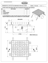
PLUMBING CONNECTIONS
SIZE OF BOILER FITTINGS
Front View
2
6
5
4
Back View
8
3
1
7

September 2012 Page
16
INDOOR BOILER : CONNECTIONS
(OUT DOOR BOILERS ASSEMBLED AT FACTORY, INDOOR UNITS SHIPPED WITH COMPOTES BOXED AND STORED IN
FUEL CHAMBER FOR PROTECTION DURING SHIPPING)
INSTALL COMPONENTS AS FOLLOWS AND LOCATE PER REFERENCE CHART AND DIAGRAM ON PREVIOUS PAGE.
PRESSURE TEMPERATURE GAUGE (#2)
• Apply pipe sealer and Te on tape to threads.
• Install in threaded coupling in upper left front of boiler.
• Tighten with proper wrench.
• Do not over tighten.
AQUASTAT WELL (#4) (WELL NORMALLY FACTORY INSTALLED)
• Apply pipe sealer and Te on tape to threads.
• Install in threaded coupling in upper right front of boiler.
• Tighten with proper wrench.
• Install aquastat housing over the head of the aquastat well.
• Do not over tighten.
DRAFT BLOWER
• Mount the draft blower using the gasket to the front of the boiler with the three screws furnished.
• Ensure that the gasket seals tightly between the blower and the appliance ange.
BOILER DRAIN VALVES (#5 & #6):
• Apply pipe sealer and Te on tape to threads.
• Install boiler drain valves in threaded anges located in front #5 & 6 (steel plugs can be substituted).
• Tighten with proper wrench.
• Do not over tighten.
PRESSURE RELIEF VALVE (#3)
• A) Apply pipe sealer and Te on tape to threads.
• B) Install in threaded coupling in upper center back of boiler.
• C) Tighten pressure relief valve with proper wrench.
• D) Do not over tighten.
Before lling the system, ensure the pressure relief valve is installed. Use only a boiler relief valve
set to limit pressure to 30 psi. Failure to comply with these guidelines could result in failure of
the relief valve to operate, resulting in possibility of severe personal injury, death or substantial
property damage.
To avoid water damage or scalding due to relief valve operation:
• Discharge line must be connected to relief valve outlet and run to a safe place of disposal. Terminate the
discharge line to eliminate possibility of severe burns should the valve discharge.
• Discharge line must be as short as possible and be the same dimension as the valve discharge connection
throughout its entire length.
• Discharge line must pitch downward from the valve and terminate at least 6” above the oor drain where any
discharge will be clearly visible.
• The discharge line shall terminate plain (OPEN), not threaded, with a material serviceable for temperatures of
200°F or greater (copper, black pipe, galvanized or Pex-Al-Pex).
• Do not pipe the discharge to any place where freezing could occur.
PRESSURE RELIEF VALVE (#3) (CONT.)
COMPONENT ASSEMBLY
DANGER

September 2012 Page
17
• No shuto valve shall be installed between the relief valve and boiler, or in the discharge line. Do not plug or
place any obstruction in the discharge line.
• Test the operation of the valve after lling and pressurizing system by lifting the lever. Ensure the valve
discharges freely. If the valve fails to operate correctly, replace it with a new relief valve.
WIRE HANDLES (4)
Turn the wire handles on to the levers in a clockwise direction.
LOW WATER CUT OFF (IF REQUIRED)
Some State and Local Codes and some Insurance Companies require a Low Water Cut O device (LWCO)
when the heat source is installed above radiation. If required, the LWCO must be installed at a high point in the
system, in a Tee near the top of the boiler.
AUTOMATIC FILL VALVES
These devices help maintain water volume in the advent that the relief valve has a discharge event. It is more dif-
cult to recognize a leak in a system with a valve continuously making up lost water. If an auto ll valve is installed,
it is recommended that a routine system check for leaks be established. Also careful monitoring of the relief valve
discharge area should be conducted.
If a feed water line and valve are incorporated, a back ow preventer is required to preclude
heating system water from entering the domestic system.
INSTALLATION: ELECTRICALS BASIC ELECTRICALS
For your safety, turn o electrical power supply at service entrance panel before making any electrical
connections to avoid electric shock hazard. Failure to do so can cause severe personal injury or death.
Ensure power is shut o while making connections. Failure to do so may result in
severe personal injury or death.
To ensure that the appliance always has ow when operating, it is recommended that the pump
and the appliance receive power from the same breaker. This is most important if the pump is
located remote from the appliance in the structure being heated. DO NOT apply power to the
pump until system has been lled. The pump is water cooled and must never be run dry due to
risk of damage from overheating.
WARNING
DANGER
WARNING
PRESSURE RELIEF VALVE (#3) (CONT.)

September 2012 Page
18
ELECTRICAL INSTALLATION MUST COMPLY WITH
• National Electrical Code and any other national, state, provincial or local codes or regulations.
• In Canada, CSA C22.1 Canadian Electrical Code Part 1, and any local codes.
Appliance must be electrically grounded as required by National Electrical Code ANSI/NFPA 70–latest edition.
Ensure ground wiring is installed per wiring diagram. Good grounding is extremely important for
proper operation.
OUTDOOR MODELS require power to be brought into the junction box on the rear of the unit and to the water
pump (not supplied). The low side of the Aquastat may be used to signal a safety heat relief zone.
INDOOR MODELS:
1) The following components are not included and must be provided by the installer:
• 4 x 4 junction box
• (2) SPST switches
2) Attach 4 x 4 junction box to the boiler.
3) Route power (115 V, 60 Hz, 15 Amp) to the junction box.
4) Connect the MASTER switch:
• Connect power “Hot” (Black) to one side
• Wire nut a lead from the other side to both the FAN switch and to the pump
5) Route power from the other side of the FAN switch to the aquastat, attach to “R”.
6) Route power from the aquastat (“B”) to the blower:
• Connect Black wire to Black wire on blower
• Connect White wire to one White wire on blower
• Connect Green wire to Green screw in blower junction box
7) Connect white common wires from the blower and pump to the White wire from the power supply.
The pump will operate when the MASTER switch is in the ON position. Operating the
pump without water in the system will damage the pump.
8) Route power to the pump.
9) Connect pump using conduit with Black, White, and Green wire.
• Open pump junction box cover
• Remove one knockout and fasten conduit to pump junction box
• Connect Black wire to one White wire on pump
• Connect White wire to one White wire on pump
• Connect Green wire to pump grounding screw in pump junction box
ELECTRICAL
NOTICE
/