

Automatic boiler for wood pellets
1
Manufacturer address:
PONAST spol. s.r.o., Na Potuckach 163, 757 01 Valasske Mezirici, CZECH REPUBLIC
http://www.ponast.cz
We would like to focus your attention mainly on the following chapters:
No. 1 – Important notes
No. 5 – Putting the product into operation
No. 6 – Maintenance and attendance of the boiler during operation
The boiler has been approved for operation in the Czech Republic and in 27 EU countries by the State Testing Institute,
state testing plant number 202.
General information on CAA and smoke control
The Clean Air Act 1993 and Smoke Control Areas
Under the Clean Air Act local authorities may declare the whole or part of the district of the authority to be a smoke
control area. It is an offence to emit smoke from a chimney of a building, from a furnace or from any fixed boiler if
located in a designated smoke control area. It is also an offence to acquire an "unauthorised fuel" for use within a smoke
control area unless it is used in an "exempt" appliance ("exempted" from the controls which generally apply in the smoke
control area).
The Secretary of State for Environment, Food and Rural Affairs has powers under the Act to authorise smokeless fuels or
exempt appliances for use in smoke control areas in England. In Scotland and Wales this power rests with Ministers in
the devolved administrations for those countries. Separate legislation, the Clean Air (Northern Ireland) Order 1981,
applies in Northern Ireland. Therefore it is a requirement that fuels burnt or obtained for use in smoke control areas have
been "authorised" in Regulations and that appliances used to burn solid fuel in those areas (other than "authorised"
fuels) have been exempted by an Order made and signed by the Secretary of State or Minister in the devolved
administrations.
The KP12S, KP22S, KP52S, KP62S , KP82S boilers have been recommended as suitable for use in smoke control areas
when burning wood pellet.
Further information on the requirements of the Clean Air Act can be found here: http://smokecontrol.defra.gov.uk/
Your local authority is responsible for implementing the Clean Air Act 1993 including designation and supervision of
smoke control areas and you can contact them for details of Clean Air Act requirements.

Automatic boiler for wood pellets
2
CONTENT
1 USE OF THE BOILER AND ITS ADVANTAGES ...................................................................................................... 5
2 STRUCTURAL DESCRIPTION OF PRODUCTS ....................................................................................................... 6
3 BOILER BODY, SCHEME OF THE PRODUCTS AND DESCRIPTION OF THE MAIN PARTS ......................................... 7
3.1 BOILER BODY............................................................................................................................................ 7
3.2 CONTROL UNIT ......................................................................................................................................... 8
3.2.1 Boiler Function Module HZS 521-G ..................................................................................................... 9
3.2.1.1 Technical base data .................................................................................................................... 11
3.2.2 Terminal HZS 555-S with USB ......................................................................................................... 12
3.2.2.1 Technical data ............................................................................................................................ 12
3.3 BURNER HEATING CHAMBER INCL. FEEDER F1 WITH INDEPENDENT DRIVE ................................................ 14
3.4 CERAMIC PARTS ...................................................................................................................................... 15
3.5 FEEDER F1 WITH INDEPENDENT DRIVE (FROM FUEL STORAGE)................................................................. 15
3.6 BOILER SHEATHING INCLUDING HEAT INSULATION .................................................................................. 17
3.7 CLEANING SYSTEM .................................................................................................................................. 18
3.7.1 Ash removal .................................................................................................................................. 18
3.7.2 Heat exchanger cleaning ................................................................................................................ 18
3.7.3 External ash container .................................................................................................................... 19
3.8 STANDARD ACCESSORIES ........................................................................................................................ 20
3.9 OPTIONAL ACCESSORIES ......................................................................................................................... 20
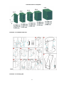
3.10 FUEL BIN ............................................................................................................................................. 20
4 PLACEMENT OF THE PRODUCT IN BOILER ROOMS, PRINCIPLES OF INSTALLATION ............................................ 22
4.1 PLACEMENT OF PRODUCTS IN BOILER ROOMS .......................................................................................... 22
4.2 SAFE DISTANCE FROM COMBUSTIBLE MATERIAL ....................................................................................... 22
4.3 LEGISLATION IN FORCE ........................................................................................................................... 22
4.3.1 Heating system and boiler .............................................................................................................. 22
4.3.2 Venting ......................................................................................................................................... 22
4.3.3 Fire regulations .............................................................................................................................. 23
4.3.4 Electrical ....................................................................................................................................... 23
4.3.5 Protection against noise .................................................................................................................. 23
4.4 STORAGE OF FUEL .................................................................................................................................. 23
4.5 BOILER ROOM VENTILATION ................................................................................................................... 23
5 PUTTING THE PRODUCTS INTO OPERATION .................................................................................................... 24
5.1 CONNECTION TO THE SYSTEM ................................................................................................................. 24
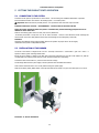
5.2 INSTALLATION OF THE BURNER ............................................................................................................... 24
5.3 INSTALATION OF THE CERAMIC CATALYTIC REFLECTOR ........................................................................... 25
5.4 INSTALLATION OF SECONDARY CERAMIC GRATE ...................................................................................... 26
5.5 INSTALLATION OF CERAMIC SHIELD ........................................................................................................ 28
5.6 CERAMIC DOOR JACKETING ..................................................................................................................... 28
5.7 CONNECTION OF ELECTRICAL PARTS ....................................................................................................... 29
5.8 CHECKING TASKS BEFORE BOILER FIRST OPERATION ............................................................................... 31
6 BOILER SERVICE AND MAINTANANCE DURING OPERATION .............................................................................. 31
6.1 SERVICE ................................................................................................................................................. 31
6.1.1 Refuelling ...................................................................................................................................... 31
6.1.2 Emptying of the external container .................................................................................................. 31
6.1.3 Flue gases exchanger cleaning ........................................................................................................ 32
6.2 MAINTANANCE ........................................................................................................................................ 32
6.2.1 Burnt gases exchanger cleaning ...................................................................................................... 32
6.2.2 Burner grate cleaning ..................................................................................................................... 33
6.2.3 Ceramic grate cleaning ................................................................................................................... 33
6.2.4 Annual audit .................................................................................................................................. 34
7 DISPOSAL OF PRODUCT AFTER TEH END OF ITS SERVICE LIFE......................................................................... 36
7.1 NATURAL PERSON ................................................................................................................................... 36
7.2 LEGAL ENTITY ......................................................................................................................................... 36
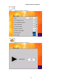
8 CONTROL UNIT OPERATION ........................................................................................................................... 37
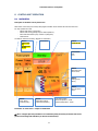
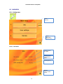
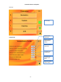
8.1 MAIN MENU ............................................................................................................................................ 37
8.2 OPERATING CONDITIONS – MAIN MENU ................................................................................................... 38
8.3 MAIN MENU ............................................................................................................................................ 39
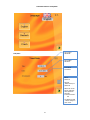
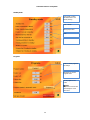
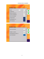
8.3.1 Setting menu ................................................................................................................................. 39
8.3.1.1 Info menu .................................................................................................................................. 39
8.3.1.2 Menu users settings .................................................................................................................... 40
8.3.1.3 Menu Service .............................................................................................................................. 43
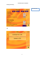
8.3.2 Menu – heating circuits ................................................................................................................... 53
8.3.2.1 Tank .......................................................................................................................................... 54

Automatic boiler for wood pellets
3
8.3.2.2 Sanitary water ............................................................................................................................ 56
8.3.2.3 Heating circuit ............................................................................................................................ 58
9 GUARANTEE AND LIABILITY FOR DEFECTS ...................................................................................................... 61
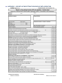
10 APPENDIX 1 - TECHNICAL DATA OF THE BOILERS KP X2S................................................................................. 67
10.1 INSTALLATION DIMENSION OF BOILER ................................................................................................. 67
10.2 TECHNICAL DATA ................................................................................................................................. 69
11 APPENDIX 2 - REPORT ON THE PUTTING THE BOILER KP INTO OPERATION ...................................................... 72
12 APPENDIX 3 - SELF-ADHESIVE LABEL - IMPORTANT SAFETY INFORMATION ....................................................... 73
PICTURES
Picture No. 1 Boiler body ................................................................................................................................6
Picture No. 2 Boiler body – description of the main parts .............................................................................7
Picture No. 3 Control unit - configuration ......................................................................................................8
Picture No. 4 HZS 521-G Connector and terminal electronics layout ............................................................9
Picture No. 5 Module HZS 532-1.................................................................................................................. 10
Picture No. 6 Other modules ........................................................................................................................ 10
Picture No. 7 Terminal with USB ................................................................................................................. 12
Picture No. 8 Burner ..................................................................................................................................... 14
Picture No. 9 Feeder F1 ................................................................................................................................ 16
Picture No. 10 Jacketing KP 12S .................................................................................................................. 17
Picture No. 11 Ash removal system ............................................................................................................. 18
Picture No. 12 Heat exchanger cleaning ...................................................................................................... 19
Picture No. 13 External ash container ......................................................................................................... 19
Picture No. 14 Standard fuel bin sizes ......................................................................................................... 21
Picture No. 15 Assembly guide ..................................................................................................................... 21
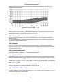
Picture No. 16 Required chimney draft ........................................................................................................ 23
Picture No. 17 Burner installation ................................................................................................................ 24
Picture No. 18 Ceramic reflector .................................................................................................................. 25
Picture No. 19 Parts of secondary ceramic grate ........................................................................................ 26
Picture No. 20 Ceramic grate parts placement guide .................................................................................. 27
Picture No. 21 Ceramic shield ...................................................................................................................... 28
Picture No. 22 Ceramic top placement guide .............................................................................................. 28
Picture No. 23 Main menu – sample of visualisation ................................................................................... 37
Picture No. 24 Principle of the modulation .................................................................................................. 62
Picture No. 25 Directory information - consumption wood pellets for boiler family KP ............................ 63
Picture No. 26 Circuit diagram – control unit .............................................................................................. 64
Picture No. 27 Circuit diagram + module HZS 533...................................................................................... 65
Picture No. 28 Circuit diagram - HZS 533, HZS 535 .................................................................................... 66

Automatic boiler for wood pellets
4
IMPORTANT NOTES
This product may only be put into operation by an installation organization trained by the manufacturer.
This product may only be operated by adult persons, duly acquainted with the way the product is controlled and duly
acquainted also with these Instructions. If you adhere to the below mentioned principles, the product will serve you
reliably to your full satisfaction.
1) It is prohibited to intervene in any way in the structure or electrical installation of products. Having the
equipment been disconnected from the electric network, the power supply cord has to be plugged from the
mains outlet.
2) It is prohibited to use inflammable liquids for ignition.
3) No inflammable materials may be stored on the boiler; neither may they be stored within the distance of 1,500
mm from the boiler (except for operating metal fuel bin).
4) In order to preserve long-term service life of the boiler body, it is not recommended to operate the boiler
frequently under the temperature of 55°C, if the boiler is not protected with a primary circuit. The temperature of
55°C should be considered as the minimum temperature.
5) The check how the boiler is filled with fuel is only visual. Any verification with touch is prohibited as it may result
in injury.
6) Never open door of the boiler if there is an ignition process.
7) The door of the boiler has to be always tightly closed. If you´ll perform any check, open the door carefully to
prevent from getting jeopardized by gathered products of combustion or to prevent any sparks flying out from
the boiler from being the cause of any accident. Open the door slowly in order to get the combustion chamber
aerated towards the chimney. This procedure has to be adhered to when the ash is being removed from the ash
pan's space.
8) If any work which generates inflammable vapours takes place in the boiler room (glueing the floor, etc.), the
boiler has to be out of operation and the fire has to be burnt out in the boiler.
9) Having the heating season been finished, clean the boiler thoroughly as per the chapter Maintenance. Products of
combustion stuck to the walls of the exchanger may act corrosively for the whole period of time when the boiler
will be out of operation. If the burner is not cleaned, this may have effect on faulty combustion. We recommend
hire a specialized company to perform this work.
10) If you work on or near to the mechanically movable parts (fuel feeder, etc.), ensure safe disconnection of the
equipment from electric voltage. There is a risk of injury.
11) You should always operate the boiler only under parameters and in harmony with recommendations given in
these instructions for installation and operation. If the boiler works in the AUTO mode and if there is a failure of
current, the boiler will start operation again with the electric firing programme (if this programme has been
installed) after the delivery of electric current is restored.
12) The manufacturer does not assume any liability for errors and subsequent damage caused by unskilled operation
of the equipment or by infringement of principles given in these instructions for installation and operation or by
infringement of generally binding standards and regulations or by using inadequate fuel.
13) If the boiler is moved or otherwise handled with, safety regulations which apply to handling with heavy loads
have to be adhered to.
14) It is prohibited to place heavy loads on jacketing boiler and to step on it. It is recommended to remove the
protective foil after all the building and installation work has been completely finished.
15) External ashtray has to be firmly connected to a boiler fitting while in the operation. Cover of this ashtray has to
be tightly closed. There could be a dangerous escape of combustion gases into a boiler room.

Automatic boiler for wood pellets
5
1 USE OF THE BOILER AND ITS ADVANTAGES
The series of automatic hot-water boilers for wood pellets is designed mainly to heat family houses, small municipal
buildings, cottages and small plants or business buildings.
The main advantages of products:
1) AUTOMATIC OPERATION ensured by the control unit which cooperates with the indoor thermostat, thermostat of
SW tank for hot water, outside thermometer in the mode of equitherm regulation, eventually by superior control
system, which ensures comfort for the user including maximum saving of fuel.
2) Automatic ASH REMOVING and heat EXCHANGER CLEANING ensures long time maintenance free and maximum
comfort of heating while keeping high burning efficiency.
3) CONTROL UNIT with modern design – controls operation of the boiler, ensures automatic operation, high
operational reliability and long distance control.
Colour TFT display 5.7" with touch screen.
Remote control over TCP/IP
USB
User friendly controlling
Operation modes: Equitherm, Modulation or Fixed power
Two heating circuits and sanitary water in basic configuration
Possibility to control accumulation tank or solar system – maximum 7 heating circuits
Upgrading software over USB stick
4) PRIORITY HEATING of sanitary water – is secured by the structure and software package of the boiler without
any need for other control elements.
5) MODULATION PERFORMANCE of the boiler allows adjusts production of the heat to an actual need of the
building.
6) Heating in EQUITHERM regulation mode lowers the cost of the heating.
7) The burner system used with two independent feeders and with a system of ceramic catalytic reflector and grate
ensures perfect SMOKELESS FUEL COMBUSTION, which supports high thermal efficiency of the product and also
excellent ecological parameters with the minimum content of harmful substances in combustion products (20-50x
less than conventional boilers).
8) SAFETY OF OPERATION ensured by separated structure of fuel transport routes and by the selected transport
mode.
9) DESIGN AND SURFACE – jacketing of the products is coated with a heavy-duty COMAXITE COATING which is
perfectly resistant to environment effects and ensures perfect appearance of products on long-term basis. Design
of whole solution is using modern shape elements.
10) This SUBSIDIED ABLE PRODUCT – is fulfilling all required conditions for obtaining subsidies in many states of the
European Union.
11) LONG DISTANCE CONTROL and monitoring by internet or GSM connection.

Automatic boiler for wood pellets
6
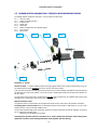
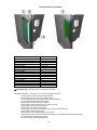
2 STRUCTURAL DESCRIPTION OF PRODUCTS
The structure adheres to the standard EN 303.5 / 2000 i.e. boilers for central heating - part 5 (boilers for
central heating with automatic fuel feed of rated heat output up to 300 kW).
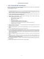
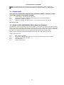
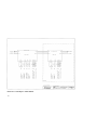
PRODUCT MAIN PARTS – FRONT SIDE
PRODUCT MAIN PARTS – BACK SIDE
Picture No. 1 Boiler body
Control unit – boiler function modules
External ashtray
Connection flexible hose
Primary fan
Boiler cover
Terminal with USB
Cleaning mechanism
Inspection door
Cleaning motor
Feeder F2
Exhaust pipe
Heating water output
Feeder F1
Backwater input

Automatic boiler for wood pellets
7
3 BOILER BODY, SCHEME OF THE PRODUCTS
AND DESCRIPTION OF THE MAIN PARTS
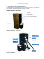
3.1 BOILER BODY
is made of top-quality steel metal sheets and pipes for boiler in form of a weldment. Its shape is adapted in such a way
so that combustion products are cooled down efficiently at individual levels of power output, which is, moreover, assisted
by a system of turbulators. The exchanger is shaped in such a way so that the exhaust pipes of combustion products can
be cleaned individually and efficiently.
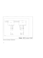
Picture No. 2 Boiler body – description of the main parts
Steel weldment
with heat exchanger
Inspection door
Exhaust pipe 130, 150 or 160 mm
Heating water output water G 1½“
(inside thread)
Backwater input water G
1½“(inside thread)
Rear flanged hole
to install the burner system
Pipe G ½“to install filling valve
Pipe with inside thread M48x2
mm to install an electrical
heating unit (optional)
Flanged hole to install ash
removing system
Opening on top for
cleaning covered by a lid
of the boiler´s body
Thermo well for sensor
and thermostat
Emergency thermostat holder

Automatic boiler for wood pellets
8
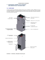
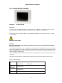
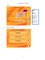
3.2 CONTROL UNIT
Boiler is equipped with the control system with touch screen. This control system enables automatic boiler operation
through the control and regulation features (thermostats, sensors, etc.) in the requested modes. It also enables
Diagnostics mode of control, which can be used for instance for boiler commissioning.
The control system construction and its electrical shielding (IP 45) make safe and reliable operation possible even under
the demanding operational and climatic conditions common to boiler rooms.
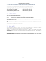
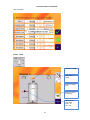
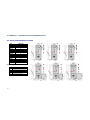
Basic configuration Optional configuration
Picture No. 3 Control unit - configuration
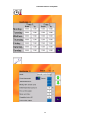
Configuration:
Name
Type
Options
Order code
Control unit - boiler function module
HZS 521-G
Standard
Terminal (touchscreen)
HZS 555-S
Standard
Module extension
HZS 532-1
Standard
Module heating circuit / accumulation tank
HZS533
Optional
Module solar
HZS535
Optional
Type and number of circuit
Type and number of module
HC1
SWT
HZS 521-G
HZS532-1
HC1
HC2
SWT
HZS 521-G
HZS532-1
HC1
HC2
HC3
SWT
HZS 521-G
HZS532-1
1 pc
HZS 533
HC1
HC2
HC3
HC4
SWT
HZS 521-G
HZS532-1
2pcs
HZS 533
HC1
HC2
HC3
HC4
HC5
SWT
HZS 521-G
HZS532-1
3pcs
HZS 533
HC1
HC2
HC3
HC4
HC5
ACU
HZS 521-G
HZS532-1
3pcs
HZS 533
HC1
HC2
HC3
HC4
ACU
SOL
HZS 521-G
HZS532-1
2pcs
HZS 533
HZS 535
HC – heating circuit
SWT – sanitary water tank
ACU – accumulation tank
SOL – solar system

Automatic boiler for wood pellets
9
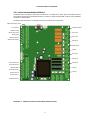
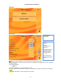
3.2.1 Boiler Function Module HZS 521-G
The heating system is modularly constructed. The HZS 521-G is a module for the boiler, which communicates with the
CPU module and executes the transmitted instructions. The HZS is a simple component that is used to control automated
processes in a heating system.
All interfaces and connections for controlling of the boiler are located on the control board.
Picture No. 4 HZS 521-G Connector and terminal electronics layout
Ambient temperature sensor
HC1 mix temp
Backwater temp
Sanitary water temp
Exhaust temp
Sanitary water top
Sanitary water bottom
Room thermostat 3
Room thermostat 2
SWT thermostat
Room thermostat 1
Impulse sensor 2
Impulse sensor 1
Room thermostat 4
Antifrost protection
Servo open
Servo close
SWT pump
Bypass pump
Ignition
HC1 pump
Primary fan
Exhaust fan
Feeder 1
Feeder 2

Automatic boiler for wood pellets
10
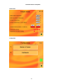
The control unit always contains modules HZS 521-G and HZS 532-1.
Picture No. 5 Module HZS 532-1
HZS533 HZS533 HZS535
Picture No. 6 Other modules

Automatic boiler for wood pellets
11
3.2.1.1 Technical base data
HZS521-G
Supply voltage
230 V AC +/- 10 %
(Input voltage for the power transformer on the power board, input
voltage for the STB, phase for the phase angle, relays and Triac outputs)
Power supply fre-
quency
45 - 65 Hz
Current
consumption of
supply (230 V AC)
Total current consumption 200 mA + current consumption of the
connected loads (max. 16 A)
Power supply transformer
Supply for the power board and CPU electronics
Supply for Heater Lambda sensor: 200 mA
The power supply is switched of STB, L-STB
Loads connected over fuse F4 (3,15 AT):
X11 primary fan: maximum
690 W/ maximum 3 A
Loads connected over fuse F5 (10 AT):
X14
Screw: maximum 690W/ maximum 3 A
Loads connected over fuse F6 (10 AT):
X9 Turbine: maximum 2300 W/ maximum 10 A
Loads connected over fuse F7 (10 AT):
X8 Ignition: maximum 2300 W/ maximum 10 A
Loads connected over fuse F8 (10 AT):
X5 heat exchange cleaner: maximum 690 W/ maximum 3 A
X6 grate open: maximum 690 W/ maximum 3 A
X7 grate closed: maximum 690 W/ maximum 3 A
The power supply not switched over STB, L
Loads connected over fuse
F9 (10 AT):
X10 boiler circuit return flow pump: maximum 2300 W/ maximum 10 A
HZS532-1
Internal
electronics power
supply
+24 V (from HZS 511), must be connected to the expansion
controller
Relay power
supply
230 VAC
Fuse
10 A for relay outputs
+24 V current
consumption
HZS 532-1: maximum 60 mA (without relays) Maximum
120 mA (with relays) HZS 532-1 with 5 expansion modules,
maximum 350 mA
HZS533, HZS535
Internal
electronics power
supply
+24 V (from HZS 511), must be connected to the expansion
controller
Relay power
supply
230 VAC
Fuse
5 A for relay outputs and/or 3 A for solar module
+24V current
consumption
HZS 533 maximum 15 mA (without relays) Maximum 40
mA (with relays)

Automatic boiler for wood pellets
12
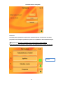
3.2.2 Terminal HZS 555-S with USB
Picture No. 7 Terminal with USB
Description
The HZS 555-S is an intelligent terminal for programming and visualization of automated processes. Process
diagnosis as well as operating and monitoring automated procedures is simplified using this terminal.
A touch screen serves as the input medium for process data and parameters. The output is shown on a 5.7" SVGA
TFT color display.
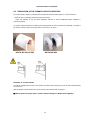
Cleaning the Touch Screen
CAUTION!
Before cleaning the touch screen, the terminal must first be turned off to avoid unintentionally triggering
functions or commands!
The terminal's touch screen can only be cleaned with a soft, damp cloth. To dampen the cloth, a screen-cleaning
solution such as antistatic foam, water with detergent or alcohol should be used. First spray the cleaning fluid on the
cloth and not directly on the terminal. The cleaning solution should not be allowed to reach the terminal electronics, for
example, through the ventilation slots.
No erosive cleaning solutions, chemicals, abrasive cleansers or hard objects that can scratch or damage the touch screen
may be used.
If the terminal is soiled with toxic or acidic chemicals, quickly and carefully clean the terminal to prevent corrosion.
3.2.2.1 Technical data
Supply voltage
Typically +24 V DC
MIN +18V DC MAX +30V DC
Current
consumption of
voltage supply
Typically 440 mA (pro + 24 V) ,
Maximum 650 mA
Standby
Typically 0.56 W
Starting current
Maximum 25 A for 20 μs

Automatic boiler for wood pellets
13
Display
Type
5.7" LCD colour display
resolution
VGA 640 x 480 Pixel
Colour depth
18-bit RGB (262K colours)
LCD Mode
TN / normal white
LCD Polarizer
Trans missive
Pixel size
0.18 mm x 0.18 mm
Active surface
115.2 mm x 86.4 mm
Background lighting
LED
Contrast
600
Brightness
Typically 350 cd/m²
Angle CR >= 10
Left, right, below 75°, above 60°
Environmental conditions
Storage temperature
-10 – +85 °C
Operating temperature
0 – 50 °C
Humidity
10 - 90 %, uncondensed
EMV stability
EN 61000-6-2: noise immunity
EN 61000-6-4: noise emission
Vibration - tolerance
EN 600068-2-6
2 - 9 Hz: Amplitude 3.5 mm
9 – 200 Hz: 1 g (10 m/s²)
Shock resistance
EN 60068-2-27
15 g (150 m/s²)
Protection Type
EN 60529 Protected
through the housing
Front: IP54
Cover: IP20

Automatic boiler for wood pellets
14
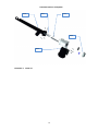
3.3 BURNER HEATING CHAMBER INCL. FEEDER F1 WITH INDEPENDENT DRIVE
The heating chamber is depicted in picture Nr. 1 and is comprises of these parts:
4.3.1 The burner body
4.3.2 Feeder F2 including the drive
4.3.3 Impulse sensor
4.3.4 Flexible hose
4.3.5 Primary fan
4.3.6 Electric resistance spiral for automatic ignition
4.3.7 Cover of spiral
4.3.8 Burner grate
Picture No. 8 Burner
The burner body – is a hollow weldment made from highly legated material with a bottom transversal fuel inlet. The
fuel is delivered by a built-in
F2 feeder
driven by an electric motor with a gearbox.
A set of slit and round jets in the burning grill ensures inflow of air in order to facilitate controlled full burning of delivered
fuel during its stay in the burner chamber. The burned out fuel is subsequently pushed over the edge of the chamber into
the ash receiver.
The inner space of the burner body is connected to an
air fan
, whose revolutions can be regulated within a large range
depending on the required boiler output or the type of fuel being used.
Impulse revolution sensor
The gearboxes of the F1 and F2 feeders are equipped with impulse sensors, which ensure safe operation of the boiler.
Connecting hose to the F1 feeder made of inflammable material connect Feeder F1 and Feeder F2. It is part of the
transfer fuel lines. It must meet strict installation rules:
It cannot have significant folds, which would block smooth fuel movement and must be built with inclination of minimum
50º (in a relation to horizontal plane).
Attachment to both adaptors must be tight.
Cleaning burner provides removal of excessive ash or cinder volume from the burner when burning lower
quality fuel. The drive of the cleaning mechanism works together with ash cleaning.
4.3.3
4.3.1
4.3.8
4.3.2
4.3.4
4.3.5
4.3.6
4.3.7

Automatic boiler for wood pellets
15
Note:
Use of alternate fuels requires change of the burner type and also change of boiler program setup.
Note:
The cleaning mechanism burner drive and its installation are depicted in chapter 4.7 – Cleaning system.
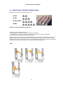
3.4 CERAMIC PARTS
These parts are an inseparable component of the combustion chamber of the boiler and they
have a major influence on the quality of burning.
4.4.1 Ceramic reflector – placed on the top of the burner
4.4.2 Ceramic secondary grate – placed in the boiler body above the burner heating chamber
4.4.3 Ceramic plate – placed above the door
4.4.4 Ceramic door jacketing– mounted on the door, or on the sides of the boiler body (at KP 82)
(See cap. 5.3 – 5.6)
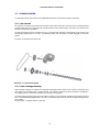
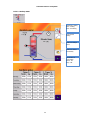
3.5 FEEDER F1 WITH INDEPENDENT DRIVE (FROM FUEL STORAGE)
F1 feeder delivers fuel from fuel storage to the burning chamber. It comprises of a pipe delivery path with an overflow
part and an end sleeve. The feeder is built into the fuel storage under an angle, which cannot exceed 45º. If the angle
was any bigger, fuel could be dispensed inaccurately. The transporter has its own electric drive, which is controlled by
the control unit. The feeder is supplied in various lengths accommodating specific types of storage tanks.
Feeder F1 and F2 gearboxes are equipped with impulse sensors, which ensure safe operation of the boiler.
Feeder F1 set comprises of:
4.5.1 Body of feeder with flange
4.5.2 Axle-less spiral (diameter 38mm in KP 12S, KP 22S, KP 52S; diameter 52mm in KP 62S, KP 82S)
4.5.3 A small bar for mounting of the spiral
4.5.4 Motor and gearbox
4.5.5 Impulse revolution sensor

Automatic boiler for wood pellets
16
Picture No. 9 Feeder F1
4.5.1
4.5.2
4.5.3
4.5.4
4.5.5

Automatic boiler for wood pellets
17
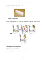
3.6 BOILER SHEATHING INCLUDING HEAT INSULATION
The product sheathing is manufactured from steel sheet metal. It is painted with durable paint applied with the powder
painting technology (KOMAXIT), which is highly resistant to outside conditions and ensures long-term perfect look of the
product. Heat insulation 8 cm thick is done with heat insulation ROCKWOL boards.
The sheathing consists of the following parts:
4.6.1. Left side plate – including coverings
4.6.2. Right side plate – including coverings
4.6.3. Upper cover
4.6.4. Front lower cover
4.6.5. Front upper cover
4.6.6. Back cover – including covering
4.6.7. Door cover
4.6.8. Door
Picture No. 10 Jacketing KP 12S
4.6.1
4.6.2
4.6.3
4.6.4
4.6.7
4.6.8
4.6.5
4.6.6

Automatic boiler for wood pellets
18
3.7 CLEANING SYSTEM
The automatic cleaning system of the boiler significantly affects time of service-free operation of the boiler.
3.7.1 Ash removal
Ash removal is a complex set of technical and program means, which ensure ash removal from burner heating chamber
to external ash receiver in a regular intervals. The ash is taken out by a spiral conveyor. It is driven by an electric motor
through a toothed chain transmission.
The ash removal system can be mounted on the left or on the right side. Assembly of the particular version is done in the
manufacturing facility based on an order. A professional service firm can perform a change (left/right) at the boiler
location.
The motor is connected to the control unit.
3.7.2 Heat exchanger cleaning
Heat exchanger cleaning is a complex set of technical and program means, which ensure removal of solid waste from
warm water boiler exchanger pipes in regular intervals. The cleaning is performed by linear movement of turbulators in
the exchanger pipes. It is driven by an electric motor through a lever gearbox.
The heat exchanger cleaning system can be mounted on the left or on the right side. Assembly of the particular version is
done in the manufacturing facility based on an order. A professional service firm can perform a change (left/right) at the
boiler location.
The drive motor is connected with the control unit.
Picture No. 11 Ash removal system

Automatic boiler for wood pellets
19
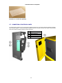
3.7.3 External ash container
The external receiver provides space for long-term ash collection outside the burning chamber. It enables long-term
service-free operation even when using fuel with high ash content. It is attached to the boiler with a detent lever. During
boiler operation the lever must be in the lower position and the connecting piping between the boiler and the ash
receiver must be tight. Also the receiver cover must be tightly closed. Both of these requirements prevent burning fumes
release to the boiler room.
The receiver is removed by moving the detent lever to the upper position and pulling it away from the boiler.
Dispensing of the contents to the waste disposal container is best done by two people because of its weight.
Picture No. 12 Heat exchanger cleaning
Picture No. 13 External ash container
Page is loading ...
Page is loading ...
Page is loading ...
Page is loading ...
Page is loading ...
Page is loading ...
Page is loading ...
Page is loading ...
Page is loading ...
Page is loading ...
Page is loading ...
Page is loading ...
Page is loading ...
Page is loading ...
Page is loading ...
Page is loading ...
Page is loading ...
Page is loading ...
Page is loading ...
Page is loading ...
Page is loading ...
Page is loading ...
Page is loading ...
Page is loading ...
Page is loading ...
Page is loading ...
Page is loading ...
Page is loading ...
Page is loading ...
Page is loading ...
Page is loading ...
Page is loading ...
Page is loading ...
Page is loading ...
Page is loading ...
Page is loading ...
Page is loading ...
Page is loading ...
Page is loading ...
Page is loading ...
Page is loading ...
Page is loading ...
Page is loading ...
Page is loading ...
Page is loading ...
Page is loading ...
Page is loading ...
Page is loading ...
Page is loading ...
Page is loading ...
Page is loading ...
Page is loading ...
Page is loading ...
Page is loading ...
-
 1
1
-
 2
2
-
 3
3
-
 4
4
-
 5
5
-
 6
6
-
 7
7
-
 8
8
-
 9
9
-
 10
10
-
 11
11
-
 12
12
-
 13
13
-
 14
14
-
 15
15
-
 16
16
-
 17
17
-
 18
18
-
 19
19
-
 20
20
-
 21
21
-
 22
22
-
 23
23
-
 24
24
-
 25
25
-
 26
26
-
 27
27
-
 28
28
-
 29
29
-
 30
30
-
 31
31
-
 32
32
-
 33
33
-
 34
34
-
 35
35
-
 36
36
-
 37
37
-
 38
38
-
 39
39
-
 40
40
-
 41
41
-
 42
42
-
 43
43
-
 44
44
-
 45
45
-
 46
46
-
 47
47
-
 48
48
-
 49
49
-
 50
50
-
 51
51
-
 52
52
-
 53
53
-
 54
54
-
 55
55
-
 56
56
-
 57
57
-
 58
58
-
 59
59
-
 60
60
-
 61
61
-
 62
62
-
 63
63
-
 64
64
-
 65
65
-
 66
66
-
 67
67
-
 68
68
-
 69
69
-
 70
70
-
 71
71
-
 72
72
-
 73
73
-
 74
74


Ponast KP 12S Service And Operation Manual
- Category
- Stoves
- Type
- Service And Operation Manual
Ask a question and I''ll find the answer in the document
Finding information in a document is now easier with AI
Related papers

Other documents
-
 Pelltech PV50b User manual
-
Centrometal PelTec Technical Instructions
-
 Pereko Q-Per series Operation and Maintenance Manual
-
ATTACK PELLET 20 A Instructions For Use Manual
-
IVAR SUPERAC 4070 Operating instructions
-
Sigma Holzgas Manual And Installation
-
 Opop Biopel 40 User manual
-
 Cichewicz Futura 35 User manual
-
 Sulzaima 18 kW Compact Boiler User manual
-
 Protherm Panther 28 KTV Operating instructions


