Page is loading ...

User Guide
UD78UD78
Servo
large option module
for Unidrive
Part Number: 0460 - 0086
Issue Number: 2

General Information
The manufacturer accepts no liability for any consequences resulting from
inappropriate, negligent or incorrect installation or adjustment of the
operating parameters of the equipment or from mismatching the Drive
with the motor.
This option module is intended for use only with Control Techniques
Unidrive products. Any other use invalidates the warranty and may cause a
safety hazard.
The contents of this Guide are believed to be correct at the time of
printing. In the interests of a commitment to a policy of continuous
development and improvement, the manufacturer reserves the right to
change the specification of the product or its performance, or the
contents of this Guide, without notice.
All rights reserved. No part of this Guide may be reproduced or
transmitted in any form or by any means, electrical or mechanical including
photocopying, recording or by any information storage or retrieval system,
without permission in writing from the publisher.
Use within the European Union, etc
The following information applies where the end use of the Drive is within
the European Union, the European Economic Area, or other regions which
have implemented Directives of the European Council or equivalent
measures.
The Drive, together with its associated option modules, complies with the
Low Voltage Directive 73/23/EEC.
The installer is responsible for ensuring that the equipment into which the
Drive is incorporated complies with all relevant Directives.
The complete equipment must comply with the EMC Directive 89/336/EEC.
If the Drive is incorporated into a machine, the manufacturer is responsible
for ensuring that the machine complies with the Machinery Directive
89/392/EEC. In particular, the electrical equipment should generally
comply with European Harmonised standard EN60204-1.
Copyright © January 2002 Control Techniques Drives Ltd
Issue Code: 78nu2

UD78 User Guide
Issue code: 78nu2
Contents
Chapter
1 Introduction 1
1.1 Main features of the UD78 1
2 Safety Information 3
3 Installing the UD78 6
4 Making Connections 8
4.1 Locations of the connectors 8
4.2 SK1
Precision analog input
connector 9
Functions of the terminals............................................................................................9
Specification.......................................................................................................................10
4.3 SK2
Back-up DC supply input
connector 11
Functions of the terminals............................................................................................11
Specification.........................................................................................................................11
Operation.............................................................................................................................12
4.4 PL1
Serial communications
connector 13
Functions of the terminals...........................................................................................13
Specification........................................................................................................................13
Serial communications modes.................................................................................14
Ground connection........................................................................................................16
Routing the serial communications cable...........................................................17
Terminating the cable....................................................................................................17
Operation..............................................................................................................................17
5 Related Parameters 18
5.1 Introduction 18
5.2
Precision analog input
parameters 19
5.3
Back-up DC supply
parameter 22
5.4
Serial communications
parameters 21

UD78 User Guide
Issue code: 78nu2
Appendix
A Serial Comms. ANSI Message Formats A-1
A.1 Fundamentals of data transmission A-1
A.2 Reading a parameter value A-4
A.3 Re-reading a parameter value A-5
A.4 Writing a parameter value A-5
A.5 Re-writing a parameter value A-6
A.6 Calculating the block checksum (BCC) A-6
B Setting up the Drive using UniSoft B-1

UD78 User Guide
Issue code: 78nu2
1
1 Introduction
1.1 Main features of the UD78
Note
The UD78 can be used only with Drives equipped with
version 3 (or later) software. (Parameter 0.50 indicates
the software version.)
Main
functions
The UD78 large option module is an interface module for installation in a
Unidrive and has the following functions:
• Precision analog input
• EIA RS485, 4-wire or 2-wire, serial communications interface (fully
opto-isolated)
• Back-up +24V
DC supply input for keeping the control circuits of the
Drive (and the UD78) operating when the AC supply to the Drive is
disconnected.
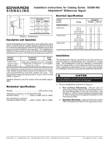
Back-up
DC
supply
Serial communications
Precision analog input
Figure 1 The functions of the UD78 connectors

UD78 User Guide
Issue code: 78nu2
2
Precision
analog input
The precision analog input replaces terminals 5 and 6 Analog input 1 in the
Drive. Terminals 5 and 6 can then not be used for any purpose. The
parameters associated with Analog input 1 now relate to the precision
input.
Serial
comms.
interface
The serial communications interface allows the following:
• The Drive to be controlled and monitored remotely by a
system controller
• The Drive to control or monitor another Drive
Installation
The UD78 must be fitted in the large option module bay of the Unidrive.
Precision analog input and serial communications connections are made by
9-way D-type connectors. The external Back-up
DC supply connections are
made by a pluggable 5-way screw-terminal block.

UD78 User Guide
Issue code: 78nu2
3
2 Safety Information
2.1
Warnings, Cautions and Notes
A Warning contains information which is essential for avoiding a safety
hazard.
A Caution contains information which is necessary for avoiding a risk of
damage to the product or other equipment.
A Note contains information which helps to ensure correct operation of the
product.
2.2 Electrical safety – general warning
The voltages used in the Drive can cause severe electric shock and/or burns,
and could be lethal. Extreme care is necessary at all times when working
with or adjacent to the Drive.
Specific warnings are given at the relevant places in this User Guide.
The installation must comply with all relevant safety legislation in the
country of use.
The Drive contains capacitors that remain charged to a potentially lethal
voltage after the
AC supply has been disconnected. If the Drive has been
energized, the AC supply must be isolated at least ten minutes before work
may continue.
2.3 System design
The Drive is intended as a component for professional incorporation into
complete equipment or systems. If installed incorrectly the Drive may
present a safety hazard. The Drive uses high voltages and currents, carries
a high level of stored electrical energy, and is used to control mechanical
equipment which can cause injury.
Close attention is required to the electrical installation and the system-
design to avoid hazards either in normal operation or in the event of
equipment malfunction. System-design, installation, commissioning and
maintenance must be carried out by personnel who have the necessary
training and experience. They must read this safety information and this
User Guide carefully.
To ensure mechanical safety, additional safety devices such as
electro-mechanical interlocks may be required. The Drive must not be used
in a safety-critical application without additional high-integrity protection
against hazards arising from a malfunction.

UD78 User Guide
Issue code: 78nu2
4
2.4 Environmental limits
Instructions in the Unidrive Installation Guide regarding transport, storage,
installation and use of Drives must be complied with, including the specified
environmental limits. Drives must not be subjected to excessive physical
force.
2.5 Compliance with regulations
The installer is responsible for complying with all relevant regulations, such
as national wiring regulations, accident prevention regulations and
electromagnetic compatibility (EMC) regulations. Particular attention must
be given to the cross-sectional areas of conductors, the selection of fuses or
other protection, and protective earth (ground) connections.
The Unidrive Installation Guide contains instructions for achieving compliance
with specific EMC standards.
Within the European Union, all machinery in which this product is used must
comply with the following directives:
89/392/EEC: Safety of Machinery
89/336/EEC: Electromagnetic Compatibility
2.6 Safety of personnel
The STOP function of the Drive does not remove dangerous voltages from
the output of the Drive or from any external option unit.
The Stop and Start controls or electrical inputs of the Drive should not be
relied upon to ensure safety of personnel. If a safety hazard could exist
from unexpected starting of the Drive, an interlock that electrically isolates
the Drive from the
AC supply should be installed to prevent the motor being
inadvertently started.
Careful consideration must be given to the functions of the Drive which
might result in a hazard, either through their intended functions (eg.
Auto-start) or through incorrect operation due to a fault or trip (eg.
stop/start, forward/reverse, maximum speed).
Under certain conditions, the Drive can suddenly discontinue control of the
motor. If the load on the motor could cause the motor speed to be
increased (eg. hoists and cranes), a separate method of braking and
stopping the motor should be used (eg. a mechanical brake).
Before connecting the
AC supply to the Drive, it is important that you
understand the operating controls and their operation. If in doubt, do not
adjust the Drive. Damage may occur, or lives put at risk. Carefully follow
the instructions in this User Guide.
Before making adjustments to the Drive, ensure all personnel in the area are
warned. Make notes of all adjustments that are made.

UD78 User Guide
Issue code: 78nu2
5
2.7 Risk analysis
In any application where a malfunction of the Drive could lead to damage,
loss of life or injury, a risk analysis must be carried out, and where necessary,
further measures taken to reduce the risk. This would normally be an
appropriate form of independent safety back-up system using simple
electro-mechanical components.
2.8 Signal connections
The control circuits are isolated from the power circuits in the Drive by basic
insulation only, as specified in IEC664–1. The installer must ensure that the
external control circuits are insulated from human contact by at least one
layer of insulation rated for use at the AC supply voltage.
If the control circuits are to be connected to other circuits classified as
Safety Extra Low Voltage (SELV) (eg. to a personal computer), an additional
isolating barrier must be included in order to maintain the SELV
classification.
2.9 Adjusting parameters
Some parameters have a profound effect on the operation of the Drive.
They must not be altered without careful consideration of the impact on
the controlled system. Measures must be taken to prevent unwanted
changes due to error or tampering.

UD78 User Guide
Issue code: 78nu2
6
3 Installing the UD78
Warning
Before using the following procedure, refer to the
Warnings at the beginning of Chapter 2 Installing the Drive in
the Unidrive Installation Guide.
1 Before installing the UD78 in the Unidrive, ensure the AC supply has
been disconnected from the Drive for at least 10 minutes.
2 Check that the exterior of the UD78 is not damaged, and that the
multi-way connector is free from dirt and debris. Do not install a
damaged or dirty UD78 in the Drive.
3 Remove the terminal cover from the Drive (for removal instructions,
see Installing the Drive and RFI filter in Chapter 2 of the Unidrive
Installation Guide).
4 Push the UD78 into the cavity immediately behind the keypad and
display until the UD78 locks in place.
5 Re-fit the terminal cover to the Drive.
6 Connect the AC supply to the Drive.
7 Set parameter .00 at 149 to unlock security.
8 Check that parameter 7.31 is set at 1 to indicate that the module is
fitted.
9 If the check in step 8 fails, perform the following:
• Remove the
AC supply from the Drive.
• Wait at least 10 minutes.
• Remove the terminal cover.
• Check that the UD78 is fully inserted.
• Replace the terminal cover.
• Re-apply the
AC supply.
• Check again that parameter 7.31 is set at
1.

UD78 User Guide
Issue code: 78nu2
7
Figure 2 Installing the UD78 in the Unidrive
Do not remove the UD78 from the Drive when either the
AC supply or a
DC back-up supply is applied to the Drive. If the UD78 is removed when the
Drive is powered-up, the Drive will trip; the display will indicate ANI.diS.
If the UD78 is deliberately removed, it may be necessary to re-adjust the
parameters related to analog input 1, since they will now relate to terminals
5 and 6.

UD78 User Guide
Issue code: 78nu2
8
4 Making Connections
Warning
The control circuits are isolated from the power circuits in
the Drive by basic insulation only, as specified in IEC664–1.
The installer must ensure that the external control circuits
are insulated from human contact by at least one layer of
insulation rated for use at the
AC supply voltage.
If the control circuits are to be connected to other circuits
classified as Safety Extra Low Voltage (SELV) (eg. to a
personal computer), an additional isolating barrier must be
included in order to maintain the SELV classification.
4.1 Locations of the connectors
Figure 3 Locations of the connectors on the UD78

UD78 User Guide
Issue code: 78nu2
9
4.2 SK1
Precision analog input connector
NC
0VD
−Vin
0VD
+Vin
0VD
0VD
SK1 [UD78]System controller
0VD
NC
0VD
−Vout
+Vout
Figure 4 Connections to the precision analog input
Functions of the terminals
Terminal Name Function
10VD0V
2 +Vin Reference input +
3 –Vin Reference input –
40VD0V
5 NC Not connected
60VD0V
70VD0V
80VD0V
9 NC Not connected
Shell 0VD 0V

UD78 User Guide
Issue code: 78nu2
10
Specification
Input type Differential
Mode Bipolar voltage
Full-scale differential input voltage ±9.8V ±1% (see parameter 7.25)
Absolute maximum differential input voltage ±30V
Absolute maximum input voltage ±50V relative to 0VD
Common mode rejection ratio 95dB
Input resistance 20kΩ
Full-scale asymmetry ±0.1% maximum
Offset error <150µV
Dead-band at zero input <150µV
Zero-crossing error <150µV
Linearity error ±0.1% of full scale
Input-filter time-constant 10µs
Resolution Open-loop: 12-bit plus sign
Closed-loop: ∞ (pulses are accumulated)
Sample period (See below)
Operating mode Destination parameter
for the analog input
PWM switching
frequency (kHz)
Sample period
Closed-loop 1.36 Analog reference 1 3, 6, 12 345µs
1.37 Analog reference 2 4, 5, 9 460µs
3.19 Hard speed reference
4.08 Torque reference
Open-loop 1.36 Analog reference 1 3, 6, 12 1.38ms
1.37 Analog reference 2 4, 5, 9 1.84ms
4.08 Torque reference
All other parameters 3, 6, 12 5.5ms
4, 5, 9 7.4ms

UD78 User Guide
Issue code: 78nu2
11
4.3 SK2
Back-up DC supply input connector
Functions of the terminals
Terminal Name Function
10VD0V
2 +DC +24 Volts supply input
3 NC Not connected
40VD0V
5 +DC +24 Volts supply input
Terminals 2 and 5 are internally connected to allow chain connection for up
to three Drives. When four or more Drives are connected, a star wiring
configuration should be used.
Specification
Required supply voltage (including ripple) 22.8V ~ 26.4V
Maximum ripple at 100Hz 1V RMS
Absolute maximum voltage +50V
Absolute maximum reverse voltage –30V
Continuous current when the AC supply is
disconnected from the Drive
<1A
Continuous current when the AC supply is
connected to the Drive
20mA
Temperature limits (See below)
Drive powered only by the back-up DC supply Up to 30°C
(86°F)
The Drive can be powered
indefinitely
Up to 40°C
(104°F)
The Drive can be powered for
15 minutes maximum
Drive powered by the AC supply
Up to 40°C
(104°F)
The Drive can be powered
indefinitely
Up to 50°C
(122°F)
Refer to the Unidrive Installation
Guide

UD78 User Guide
Issue code: 78nu2
12
Operation
For automatic operation of the back-up DC supply, this supply should be
connected continuously.
The following table shows the results of a combination of supply conditions.
A 400V
AC supply is considered to be removed when it is below
approximately 230V RMS.
AC supply Back-up
DC supply
Resulting effect
Present Present or
absent
Control circuits and power stages operate
(Drive fully operational, including the precision analog input)
Absent Present If the AC supply is present, then removed, parameters that are saved
at power-down are saved
Only the control circuits operate
The Drive cannot power a motor
The Drive displays LOPS
The Drive can be programmed either manually or via
serial communications, but parameter values cannot be saved
Model sizes 1 and 2: Heatsink fan operates
Model sizes 3 and 4: Heatsink fans do not operate
Power-up delays
The following delays occur:
AC supply disconnected
Back-up
DC supply being connected
5 second delay for Drive display and serial
communications to become active
Back-up DC supply already connected
AC supply being connected
5 second delay before the Drive can be
enabled
Note
Stator resistance test (open-loop only)
If parameter 5.14 (0.07) is set at Ur_I for the Drive to perform a stator
resistance test at power-up, and the AC supply is disconnected, the Drive
will trip if the Back-up DC supply is connected. The Drive will display trip
code rS, indicating failure to perform the stator resistance test.
To prevent this occurring, set parameter 5.14 (0.07) at one of the
following, and refer to Voltage boost in Chapter 4 Menu 0 parameters in the
Unidrive User Guide:
Ur_S, Ur, Fd

UD78 User Guide
Issue code: 78nu2
13
4.4 PL1
Serial communications connector
Functions of the terminals
Terminal Name Function
1 0VSC 0V
2 TX\ Transmit output (inverted)
3 RX\ Receive input (inverted)
4TXTERM TX termination-resistor
connection
5RXTERM RX termination-resistor
connection
6 TX Transmit output
7 RX Receive input
8TX\TERM TX\ termination-resistor
connection
9RX\TERM RX\ termination-resistor
connection
Shell 0VSC 0V
Specification
RX (input) 2 unit-loads (EIA RS485)
TX (output) 2 unit-loads (EIA RS485)
2-wire (Transceiver mode) 4 unit-loads (EIA RS485)
Termination resistance 120Ω ±5% (no series capacitor)
In accordance with the EIA RS485 specification, the total load on a line must
not exceed 32 unit-loads. Each transmitter and receiver of the UD78 loads
the line by two unit-loads (in two-wire mode, each UD78 loads the line by
four unit-loads). This allows the following to be operated:
• 15 units in 4-wire mode
• 7 units in 2-wire mode
When line repeaters are used, up to 81 Control Techniques devices can be
operated. In this case the devices must be arranged in up to nine groups of
nine. A particular group or groups can be given commands without
affecting other devices or groups of devices.

UD78 User Guide
Issue code: 78nu2
14
Group 1
Group 2
System
controller
Line
repeater
Line
repeater
Figure 5 RS485 multi-drop link having two groups of four units
Serial communications modes
The serial communications interface can be set up for operation in the
following modes:
2-wire ANSI Half-duplex communications (transceiver mode)
4-wire ANSI Half-duplex communications, independent RX and TX channels
Output The Drive is to control another Drive (CT protocol)
Input The Drive is to be controlled by another Drive (CT protocol)
Make connections as shown in Figure 6, 7 or 8 as required. If the Drive is to
be set up using Unisoft on a PC, see Appendix B Setting up the Drive using
Unisoft.

UD78 User Guide
Issue code: 78nu2
15
Four-wire ANSI
RXTERM
TXTERM
RX\
RX
TX\
TX
0VSC
PL1 [UD78]
TX\
TX
RX\
RX
System controller
0VSC
RX\TERM
TX\TERM
Figure 6 4-wire serial communications connections
Ensure parameter 11.24 Serial comms. mode selector is set at
ANSI 4 (1)
(default setting).
Two-wire ANSI
0VSC
PL1 [UD78]
TX\ RX\
TX RX
System controller
0VSC
RXTERM
TXTERM
RX\
RX
TX\
TX
RX\
TERM
TX\TERM
Figure 7 2-wire (transceiver mode) serial communications connections
Set parameter 11.24 Serial comms. mode selector at
ANSI 2 (0).

UD78 User Guide
Issue code: 78nu2
16
Output and Input modes
RX
TERM
TXTERM
RX\
RX
TX\
TX
0VSC
PL1 [UD78]
0VSC
RX\TERM
TX\TERM
PL1 [UD78]
RX
TERM
TXTERM
RX\
RX
TX\
TX
0VSC
0VSC
RX\TERM
TX\TERM
Parameter 11.24 set at
OUtPUt (2)
Parameter 11.24 set at
InPUt (3)
Figure 8 Serial communications connections for the Input and
Output modes
Data is transferred at a rate of at least 140Hz. The protocol and range of
baud rates allow communications with the Mentor II and CDE models, as
well as other Unidrive models.
Only the value of a variable parameter can be transmitted and received. Bit
parameters are excluded.
Set parameter 11.24 Serial comms. mode selector as follows:
Output mode:
OutPUt (2)
Input mode:
InPUt (3)
Output mode
The value of a variable parameter selected by parameter 11.27 Serial comms.
source selector is sent (after scaling by 11.28 Serial comms. parameter
scaling) to the serial communications port for transmission.
If the Drive trips, the value
0 is transmitted.
Input mode
The value received by the serial communications port is applied (after
scaling by 11.28 Serial comms. parameter scaling) to an unprotected variable
parameter selected by parameter 11.27 Serial comms. destination selector.
If communications fail, the Drive will trip; the display will indicate
SCL.
Ground connection
In addition to each end of the cable shield being connected to 0V, it can be
connected by a single path to a ‘clean’ ground.
/