
1
Before You Start
Your Storage Stand is exclusively designed for your Land
Pride PD10, PD15, DP25 or PD35 Post Hole Diggers.
Please read these installation instructions and your Post
Hole Digger Operator’s Manual thoroughly before
beginning. Especially read information relating to safety
concerns. Also included in the Operator’s Manual is
important information on operation, adjustment,
troubleshooting, and maintenance for this attachment
(some manual sections do not apply to all accessories).
A separate Parts Manual for your digger is available free
of charge at www.landpride.com or can be purchased
from your nearest Land Pride dealer. Have the model and
serial number of your Storage Stand handy when placing
an order.
Manual Part Numbers:
• Operator’s Manual . . . . . . . . . . . . . . . . 317-048M
• Parts Manual . . . . . . . . . . . . . . . . . . . . . 317-048P
When you see this symbol, the subsequent
instructions and warnings are serious - follow
them without exception. Your life and the lives of
others depend on it!
!
IMPORTANT: Before you begin, read these
instructions and check to be sure all parts and tools
are accounted for. Please retain these installation
instructions for future reference and parts ordering
information.
General Information
These assembly instructions apply to the following
Storage Stand Accessories listed below:
317-166A PD10 Storage Stand . . . . . . . . . . . . . . . .Page 2
317-142A PD15, PD25, & PD35 Storage Stand . . .Page 5
Tools required:
•
Safety glasses and work gloves
• Two 9/16" wrenches (PD15, PD25, & PD35 only)
• Two 3/4" wrenches
• One #13 metric wrench (PD10 only)
Further Assistance
Your dealer wants you to be satisfied with your new
storage stand. If for any reason you do not understand
any part of this manual or are not satisfied with the
service received, the following actions are suggested:
1. Discuss the matter with your dealership service
manager. Make sure he has had time to assist you.
2. If you are still not satisfied, seek out the owner or
general manager and explain the question/problem.
3. For further assistance write to:
Land Pride Service Department
1525 East North Street
P.O. Box 5060
Salina, Ks. 67402-5060
E-mail address
lpservicedept@landpride.com
For PD10, PD15, PD25 & PD35 Post Hole Diggers
Post Hole Digger Storage Stand
Assembly Instructions
Manual No. 317-413M
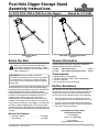
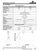
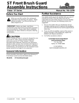
PD10 Storage Stand
Figure 1
PD15, PD25, and PD35 Storage Stand
Figure 2
20856 20776
© Copyright 2020
Printed 9/16/
20

2
Post Hole Digger Storage Stand Assembly Instructions Manual No. 317-413M 9/16/20
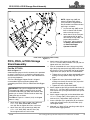
PD10 Storage Stand Assembly
PD10 Storage Stand Assembly
Part No. 317-166A
Refer to Figure 1-1:
A detailed listing of parts for this accessory kit is provided
on page 4. Use the list as a checklist to inventory parts
received. Please contact your local Land Pride dealer for
any missing hardware.
The Post Hold Digger Support Stand is shipped
unassembled. Follow instructions below when
assembling the PD10 Post Hole Digger Stand.
1. Attach lower legs (#6A) to upper legs (#6B) with
1/2" x 1 1/4" bolts (#7B) and whiz nuts (#9).
Do not tighten whiz nuts at this time.
2. Attach cross bar (#4) to legs (#6A & #6B) with
1/2" x 1 1/4" bolts (#7A) and whiz nuts (#9).
Do not tighten whiz nuts at this time.
IMPORTANT: The stand is shipped with four legs.
The upper legs (#6B) have decals (#12) and are
installed inside lower legs (#6A) with the bent ends
pointing in as shown. The bent ends on lower
legs (#6A) point out as shown.
See Note in Figure 1-1 if decals (#12) are shipped
loose in a bag.
3. Attach mount (#5) to upper legs (#6B) with
1/2" x 1 1/4" bolts (#7C) and whiz nuts (#9). Do not
tighten whiz nuts at this time.
4. Draw all assembled whiz nuts (#9) up snug. Verify
legs (#6A) align evenly with legs (#6B) and the top of
the cross bar (#4) is parallel with the top of the legs.
Torque whiz nuts (#9) to 76 ft-lbs as noted below.
a. Tighten whiz nuts (#9) on bolts (#7B) while
making sure the upper and lower legs align with
each other.
b. Tighten whiz nuts (#9) on bolts (#7A) while
making sure the top of cross bar (#4) is parallel
with the top edge of legs (#6A & #6B).
c. Tighten whiz nuts (#9) on bolts (#7C).
5. Attach support angles s (#2) on the left side of
tabs (C) on with 1/2" x 1 1/4" bolts (#7D) and nylock
nuts (#10). Draw nylock nuts up snug and then back
nut up one-half revolution.
6. Attach support angles (#2) to the slotted holes in
tabs (C) with hand knobs (#11). Hand tighten knobs.
7. Insert cradle pins (A) in slots (B) and secure
cradle (#3) to upper mount (#5) with hand
knobs (#11). Hand tighten knobs.
8. Keep M8 x 1.25 bolts (#8) for attaching cradle (#3) to
the Post Hole Digger gearbox.
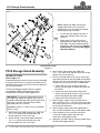
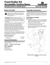
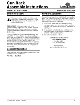
PD10 Stand Assembly
Figure 1-1
NOTE: Upper legs (#6B) are normally
shipped with decals (#12) installed. If
shipped loose, they should be installed on
the two upper legs as follows:
1. Lay the two legs (#6B) on the floor as
shown with the bent ends at the top
facing in.
2. Attach decals (#12) facing out and
approximately 8" down from the top of
legs (#6B). For proper label placement
instructions, refer to step 4 in the Safety
Label Section of the Post Hole Digger
Operator’s Manual.
73920
L
e
ft
R
ig
h
t

3
9/16/20
Post Hole Digger Storage Stand Assembly Instructions Manual No. 317-413M
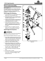
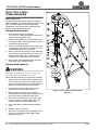
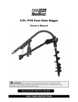
PD10 Cradle Assembly
PD10 Cradle Assembly
Refer to Figure 1-2:
The optional storage stand is used for storing the
Post Hole Digger off the ground where moisture and
debris are more likely to cause damage to the
components. It will also assist the operator while
hooking-up and unhooking the unit.
PD10 Storage Stand Assembly
1. Unscrew locknuts (#11) and remove bolts (#10).
Slide auger (#1) off of gearbox (#15).
2. Remove existing bolts (#7), lock washers (#12),
flat washers (#13), and auger guards (#3) from
underside of gearbox (#14).
3. Position cradle (#5) between auger guards (#3)
and gearbox (#14). Make sure cradle pins (#2)
are positioned to the back as shown.
4. Attach cradle (#5) and guards (#3) to the
underside of gearbox (#14) with new M8 x 1.25
bolts (#7), existing lock washers (#12), and
existing flat washers (#13). Torque bolts (#7)
to 19 ft-lbs.
5. Reattach auger (#1) to gearbox (#14) with
existing 1/2" x 3 1/2" auger bolts (#10) and
locknuts (#11). Torque locknuts to 76 ft-lbs.
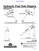
PD10 Storage Stand Operation
!
WARNING
To avoid serious injury or death: Do not disconnect Post
Hole Digger from the tractor while on a steep incline.
Injury to personnel and equipment may result.
Attach storage stand (#8) to cradle (#5) as follows:
1. Stop on solid, level ground, place tractor in park
or set tractor park brake, lower auger tip to the
ground, turn tractor engine off, and remove the
ignition key before dismounting the tractor.
2. If you stop on a gentle slope, chock tractor
wheels for an extra measure of safety.
3. Make certain guide slots (#9) are securely
positioned over cradle pins (#2). Secure storage
stand (#8) to the cradle with hand knobs (#6).
4. Start tractor and lower boom (#4) to rest yoke
hitch pins (#15) in support angles (#16). The
support angles may require adjustment.
5. Shut tractor down and disconnect three-point
hitch.
6. Remove chocks if installed.
7. Start tractor and drive away while being careful
not to catch on the Post Hole Digger and/or
Storage Stand (#8).
PD10 Storage Stand Assembly
Figure 1-2
20867

4
Post Hole Digger Storage Stand Assembly Instructions Manual No. 317-413M 9/16/20
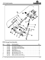
PD10 Cradle Assembly
PD10 Storage Stand Assembly
Item Part No. Part Description Qty
1. 317-166A PD10 STAND ASSEMBLY . . . . . . . . . . . . . . . . . . . . . . . . . . . . . . . . . . . . . . . . . . . . 1
2. 317-148H PD STAND HITCH WELDMENT . . . . . . . . . . . . . . . . . . . . . . . . . . . . . . . . . . . . . . . 2
3. 317-164H PD10 STAND CRADLE WELDMENT . . . . . . . . . . . . . . . . . . . . . . . . . . . . . . . . . . . 1
4. 317-412H PD10 STAND CROSS BAR WLDMNT . . . . . . . . . . . . . . . . . . . . . . . . . . . . . . . . . . 1
5. 317-435D PD10 MOUNT . . . . . . . . . . . . . . . . . . . . . . . . . . . . . . . . . . . . . . . . . . . . . . . . . . . . . 1
6. 317-436D PD10 STAND LEG . . . . . . . . . . . . . . . . . . . . . . . . . . . . . . . . . . . . . . . . . . . . . . . . . 4
7. 802-034C HHCS 1/2-13X1 1/4 GR5 . . . . . . . . . . . . . . . . . . . . . . . . . . . . . . . . . . . . . . . . . . . . 8
8. 802-314C HHCS M8X1.25X20 GR8.8 . . . . . . . . . . . . . . . . . . . . . . . . . . . . . . . . . . . . . . . . . . . 4
9. 803-037C NUT HEX WHIZ 1/2-13 PLT GR5 . . . . . . . . . . . . . . . . . . . . . . . . . . . . . . . . . . . . . . 6
10. 803-147C NUT HEX NYLOCK 1/2-13 . . . . . . . . . . . . . . . . . . . . . . . . . . . . . . . . . . . . . . . . . . . 2
11. 817-455C KNOB 1/2-13 MALE THD 2 3/8OD . . . . . . . . . . . . . . . . . . . . . . . . . . . . . . . . . . . . . 4
12. 838-298C DECAL CAUTION DO NOT LEAN ON . . . . . . . . . . . . . . . . . . . . . . . . . . . . . . . . . . 2
73917

5
9/16/20
Post Hole Digger Storage Stand Assembly Instructions Manual No. 317-413M
PD15, PD25, & PD35 Storage Stand Assembly
PD15, PD25, & PD35 Storage
Stand Assembly
Part No. 317-142A
Refer to Figure 2-1:
A detailed listing of parts for this accessory kit is provided
on page 7. Use the list as a checklist to inventory parts
received. Please contact your local Land Pride dealer for
any missing hardware.
The Post Hold Digger Support Stand is shipped
unassembled. Follow instructions below when
assembling the PD15, PD25, or PD35 Post Hole Digger
Stand.
1. Attach lower legs (#6A) to upper legs (#6B) with
1/2" x 1 1/4" bolts (#8A & #8B) and whiz
nuts (#9). Do not tighten whiz nuts at this time.
2. Attach cross bar (#4) to lower legs (#6A) with
1/2" x 1 1/4" bolts (#8D) and whiz nuts (#9).
Do not tighten whiz nuts at this time.
IMPORTANT: The stand is shipped with four legs.
The upper legs (#6B) have decals (#14) and are
installed inside lower legs (#6A) with the bent ends
pointing in as shown. The bent ends on lower legs
(#6A) point out as shown.
See Note in Figure 2-1 if decals (#14) are shipped
loose in a bag.
3. Attach mount (#5) to upper legs (#6B) with
1/2" x 1 1/4" bolts (#8C) and whiz nuts (#9). Do not
tighten whiz nuts at this time.
4. Draw all assembled whiz nuts (#9) up snug. Verify
legs (#6A) align evenly with legs (#6B) and the top of
the cross bar (#4) is parallel with the top of the legs.
Torque whiz nuts (#9) to 76 ft-lbs as noted below.
a. Tighten whiz nuts (#9) on bolts (#8A & #8B) while
making sure legs (#6A & #6B) align with each
other.
b. Tighten whiz nuts (#9) on bolts (#8D) while
making sure the top of cross bar (#4) is parallel
with the top edge of legs (#6A).
c. Tighten whiz nuts (#9) on bolts (#8D).
5. Attach support angles (#3) on the left side of tabs (C)
with 1/2" x 1 1/4" bolts (#8E) and nylock nuts (#10).
Draw nylock nuts up snug and then back nuts up one-
half revolution.
6. Attach support angles (#3) to the slotted holes with
1/2" x 1 1/4" bolts (#8F), lock washers (#11), and flat
washers (#12). Torque bolts (#8F) to 76 ft-lbs.
7. Insert cradle pins (A) in guide slots (B) and secure
cradle (#2) to upper mount (#5) with knobs (#13).
Hand tighten knobs.
8. Keep 3/8" x 1" bolts (#7) for attaching cradle (#2) to
the Post Hole Digger gearbox.
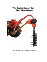
PD15, PD25, and PD35 Stand Assembly
Figure 2-1
73923
L
e
ft
R
ig
h
t
NOTE: Upper legs (#6B) are
normally shipped with decals
(#14) installed. If shipped loose,
they should be installed on the two
upper legs as follows:
1. Lay the two legs (#6B) on the
floor as shown with the bent
ends at the top facing in.
2. Attach decals (#14) facing out
and approximately 8" down
from the top of legs (#6B). For
proper label placement
instructions, refer to step 4 in
the Safety Label Section of
the Post Hole Digger
Operator’s Manual.

6
Post Hole Digger Storage Stand Assembly Instructions Manual No. 317-413M 9/16/20
PD15, PD25, & PD35 Cradle Assembly
PD15, PD25, & PD35
Cradle Assembly
Refer to Figure 2-2:
The optional storage stand is used for storing the
Post Hole Digger off the ground where moisture and
debris are more likely to cause damage to the
components. It will also assist the operator while
hooking-up and unhooking the unit.
Storage Stand Assembly
1. Unscrew locknuts (#9) and remove
1/2"-13 x 3 1/2" GR5 hex head bolts (#8). Slide
auger (#4) off of gearbox (#13).
2. Remove existing bolts (#7), lock washers (#11),
flat washers (#10), and auger guards (#2) from
underside of gearbox (#13).
3. Position cradle (#3) between auger guards (#2)
and gearbox (#13). Make sure cradle pins (#5)
are positioned to the back as shown.
4. Attach cradle (#3) and guards (#2) to underside
of gearbox (#13) with new 3/8" 16 x 1" bolts (#7),
existing lock washers (#11), and existing flat
washers (#10). Torque bolts (#7) to 31 ft-lbs.
5. Attach auger (#4) to gearbox output shaft with
auger bolts (#8) and locknuts (#9).
Storage Stand Operation
!
WARNING
To avoid serious injury or death: Do not disconnect Post
Hole Digger from the tractor while on a steep incline.
Injury to personnel and equipment may result.
Attach storage stand (#14) to cradle (#3) as follows:
1. Stop on solid, level ground, place tractor in park
or set tractor park brake, lower auger tip to the
ground, turn tractor engine off, and remove the
ignition key before dismounting the tractor.
2. If you stop on a gentle slope, chock tractor
wheels for an extra measure of safety.
3. Make certain guide slots (#6) are securely
positioned over cradle pins (#5). Secure storage
stand (#14) to the cradle with knobs (#12).
4. Start tractor and lower boom (#1) to rest yoke
hitch pins (#15) in support angles (#16). The
support angles may require adjustment.
5. Shut tractor down and disconnect three-point
hitch.
6. Remove chocks if installed.
7. Start tractor and drive away while being careful
not to catch on the Post Hole Digger and/or
Storage Stand (#14).
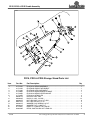
PD15, 25, and 35 Storage Stand Assembly
Figure 2-2
20872

7
9/16/20
Post Hole Digger Storage Stand Assembly Instructions Manual No. 317-413M
PD15, PD25, & PD35 Cradle Assembly
PD15, PD25 & PD35 Storage Stand Parts List
Item Part No. Part Description Qty
1. 317-142A PD15/25/35 STAND ASSEMBLY . . . . . . . . . . . . . . . . . . . . . . . . . . . . . . . . . . . . . . . 1
2. 317-144H PD STAND CRADLE WELDMENT . . . . . . . . . . . . . . . . . . . . . . . . . . . . . . . . . . . . . 1
3. 317-148H PD STAND HITCH WELDMENT . . . . . . . . . . . . . . . . . . . . . . . . . . . . . . . . . . . . . . . 2
4. 317-409H PD15/25/35 STAND BRACE WLDMNT . . . . . . . . . . . . . . . . . . . . . . . . . . . . . . . . . . 1
5. 317-433D PD15/25/35 STAND UPPER MOUNT . . . . . . . . . . . . . . . . . . . . . . . . . . . . . . . . . . . 1
6. 317-434D PD15/25/35 STAND LEG . . . . . . . . . . . . . . . . . . . . . . . . . . . . . . . . . . . . . . . . . . . . 4
7. 802-017C HHCS 3/8-16X1 GR5 . . . . . . . . . . . . . . . . . . . . . . . . . . . . . . . . . . . . . . . . . . . . . . . 4
8. 802-034C HHCS 1/2-13X1 1/4 GR5 . . . . . . . . . . . . . . . . . . . . . . . . . . . . . . . . . . . . . . . . . . . 12
9. 803-037C NUT HEX WHIZ 1/2-13 PLT GR5 . . . . . . . . . . . . . . . . . . . . . . . . . . . . . . . . . . . . . . 8
10. 803-147C NUT HEX NYLOCK 1/2-13 . . . . . . . . . . . . . . . . . . . . . . . . . . . . . . . . . . . . . . . . . . . 2
11. 804-015C WASHER LOCK SPRING 1/2 PLT . . . . . . . . . . . . . . . . . . . . . . . . . . . . . . . . . . . . . 2
12. 804-016C WASHER FLAT 1/2 SAE PLT . . . . . . . . . . . . . . . . . . . . . . . . . . . . . . . . . . . . . . . . . 2
13. 817-455C KNOB 1/2-13 MALE THD 2 3/8OD . . . . . . . . . . . . . . . . . . . . . . . . . . . . . . . . . . . . . 2
14. 838-298C DECAL CAUTION DO NOT LEAN ON . . . . . . . . . . . . . . . . . . . . . . . . . . . . . . . . . . 2
73918

Corporate Office: P.O. Box 5060
Salina, Kansas 67402-5060 USA
www.landpride.com
-
 1
1
-
 2
2
-
 3
3
-
 4
4
-
 5
5
-
 6
6
-
 7
7
-
 8
8


Ask a question and I''ll find the answer in the document
Finding information in a document is now easier with AI
Related papers
-
Land Pride PD35 User manual
-
-
-
 Land Pride PD25 Series User manual
-
 Land Pride 4220ST User manual
-
 Land Pride PD10 Series User manual
-
 Land Pride FDR25 Series User manual
-
 Land Pride HD35 User manual
-
 Land Pride 701-137M User manual
-
 Land Pride 701-148M User manual


Other documents
-
Anvil 618010 Installation guide
-
Max Load 38023 Operating instructions
-
General 210 User manual
-
 Nortrac 3-Pt. PTO Post Hole Digger Owner's manual
-
Bush Hog Posthole Digger Owner's manual
-
 Sansen FAPT1860 User manual
-
-
-
Behlen Country PHD Owner's manual
-
 Spin-Digger SDBL78 Installation guide


