Page is loading ...

S183-SH0-AAJ1
S183-SH0-AAV1
4th Gen Intel® Xeon® Scalable Server System - 1U DP 32-Bay Gen5 NVMe
Dual 2000W 80 PLUS Titanium redundant power supply (AAJ1)
Dual 1600W 80 PLUS Titanium redundant power supply (AAV1)
User Manual
Rev. 1.0

Copyright
© 2023 Giga Computing Technology CO., LTD. All rights reserved.
The trademarks mentioned in this manual are legally registered to their respective owners.
Disclaimer
Information in this manual is protected by copyright laws and is the property of Giga Computing.
Changes to the specications and features in this manual may be made by Giga Computing
without prior notice. No part of this manual may be reproduced, copied, translated, transmitted, or
published in any form or by any means without Giga Computing's prior written permission.
Documentation Classications
In order to assist in the use of this product, Giga Computing provides the following types of documen-
tation:
User Manual: detailed information & steps about the installation, conguration and use of this
product (e.g. motherboard, server barebones), covering hardware and BIOS.
User Guide: detailed information about the installation & use of an add-on hardware or
software component (e.g. BMC rmware, rail-kit) compatible with this product.
Quick Installation Guide: a short guide with visual diagrams that you can reference easily for
installation purposes of this product (e.g. motherboard, server barebones).
Please see the support section of the online product page to check the current availability of these
documents.
For More Information
For related product specications, the latest rmware and software, and other information please visit our website at
http://www.gigabyte.com/Enterprise
For GIGABYTE distributors and resellers, additional sales & marketing materials are available from our reseller
portal: http://reseller.b2b.gigabyte.com
For further technical assistance, please contact your GIGABYTE representative or visit
https://esupport.gigabyte.com/ to create a new support ticket
For any general sales or marketing enquiries, you may also message GIGABYTE server directly by email:
server[email protected]
Conventions
The following conventions are used in this user's guide:
NOTE!
Pieces of additional
information related to the current topic.
CAUTION!
Precautionary measures to
avoid possible hardware or software problems.
WARNING!
Alerts to any damage that might
result from doing or not doing specic actions.
Server Warnings and Cautions
Before installing a server, be sure that you understand the following warnings and cautions.
WARNING!
To reduce the risk of electric shock or damage to the equipment:
• Do not disable the power cord grounding plug. The grounding plug is an important safety
feature.
• Plug the power cord into a grounded (earthed) electrical outlet that is easily accessible at all
times.
• Unplug the power cord from the power supply to disconnect power to the equipment.
• Do not route the power cord where it can be walked on or pinched by items placed against it.
Pay particular attention to the plug, electrical outlet, and the point where the cord extends from
the server.
WARNING!
To reduce the risk of personal injury from hot surfaces, allow the drives and the internal
system components to cool before touching them.
WARNING!
This server is equipped with high speed fans. Keep away from hazardous moving fan
blades during servicing.
CAUTION!
• Do not operate the server for long periods with the access panel open or removed. Operat-
ing the server in this manner results in improper airow and improper cooling that can lead to
thermal damage.
• Danger of explosion if battery is incorrectly replaced.
• Replace battery with the same or equivalent type recommended by the manufacturer.
• Dispose of used batteries according to the manufacturer’s instructions.
CAUTION!
Risk of explosion if battery is replaced incorrectly or with an incorrect type. Replace the battery
only with the same or equivalent type recommended by the manufacturer. Dispose of used bat-
teries according to the manufacturer’s instructions.

Electrostatic Discharge (ESD)
CAUTION!
ESD CAN DAMAGE DRIVES, BOARDS, AND OTHER PARTS. WE RECOMMEND THAT YOU
PERFORM ALL PROCEDURES AT AN ESD WORKSTATION. IF ONE IS NOT AVAILABLE,
PROVIDE SOME ESD PROTECTION BY WEARING AN ANTI-STATIC WRIST STRAP AT-
TACHED TO CHASSIS GROUND -- ANY UNPAINTED METAL SURFACE -- ON YOUR SERVER
WHEN HANDLING PARTS.
Always handle boards carefully, they can be extremely sensitive to ESD. Hold boards only by
their edges without touching any components or connectors. After removing a board from its
protective ESD bag or from the system, place the board component side up on a grounded, static
free surface. Use a conductive foam pad if available but not the ESD bag. Do not slide the board
over any surface.
System power on/off: To service components within the server, please ensure the power has
been disconnected.
e.g. Remove the node from the server chassis (to disconnect power) or disconnect the power
from the server chassis.
Make sure the system is removed from the rack before opening the chassis, adding, or removing
any non hot-plug components.
Hazardous conditions, devices and cables: Hazardous electrical conditions may be present
on power, telephone, and communication cables. Turn off the system chassis and disconnect the
cables attached to the system before servicing the chassis. Otherwise, personal injury or equip-
ment damage can result.
Electrostatic discharge (ESD) and ESD protection: ESD can damage drives, boards, and
other parts. We recommend that you perform all procedures in this chapter only at an ESD work-
station. If one is not available, provide some ESD protection by wearing an antistatic wrist strap
attached to chassis ground (any unpainted metal surface on the server) when handling parts.
ESD and handling boards: Always handle boards carefully. They can be extremely sensi-tive to
electrostatic discharge (ESD). Hold boards only by their edges. After removing a board from its
protective wrapper or from the system, place the board component side up on a grounded, static
free surface. Use a conductive foam pad if available but not the board wrapper. Do not slide
board over any surface.

Installing or removing jumpers: A jumper is a small plastic encased conductor that slips over
two jumper pins. Some jumpers have a small tab on top that can be gripped with n-gertips or
with a pair of ne needle nosed pliers. If the jumpers do not have such a tab, take care when us-
ing needle nosed pliers to remove or install a jumper; grip the narrow sides of the jumper with the
pliers, never the wide sides. Gripping the wide sides can dam-age the contacts inside the jumper,
causing intermittent problems with the function con-trolled by that jumper. Take care to grip with,
but not squeeze, the pliers or other tool used to remove a jumper, or the pins on the board may
bend or break.

- 7 -
Table of Contents
Chapter 1 Hardware Installation ...................................................................................10
1-1 Installation Precautions .................................................................................. 10
1-2 Product Specications .................................................................................... 11
1-3 System Block Diagram ................................................................................... 15
Chapter 2 System Appearance .....................................................................................16
2-1 Front View ...................................................................................................... 16
2-2 Rear View ....................................................................................................... 17
2-3 Front Panel LEDs and Buttons ....................................................................... 18
2-4 RoT LEDs ....................................................................................................... 19
2-5 Rear System LAN LEDs ................................................................................. 21
2-6 Power Supply Unit LED .................................................................................. 22
2-7 Storage LED ................................................................................................... 23
Chapter 3 System Hardware Installation ......................................................................24
3-1 Removing and Installing the Chassis Cover .................................................. 25
3-2 Installing the EDSFF SSD .............................................................................. 26
3-3 Removing and Installing the Fan Duct ........................................................... 27
3-4 Removing and Installing the Heat Sink .......................................................... 28
3-5 Installing the CPU and Heat Sink ................................................................... 29
3-6 Removing and Installing Memory ................................................................... 31
3-6-1 Eight Channel Memory Conguration .....................................................................31
3-6-2 Removing and Installing a Memory Module ...........................................................32
3-6-3 Memory Population Table .......................................................................................32
3-6-4 Processor and Memory Module Matrix Table .........................................................33
3-7 Removing and Installing the PCIe Card ......................................................... 34
3-8 Removing and Installing the Power Supply .................................................... 35
3-9 Cable Routing ................................................................................................ 36
Chapter 4 Motherboard Components ...........................................................................41
4-1 Motherboard Components ............................................................................. 41
4-2 Jumper Settings ............................................................................................. 43
4-3 G-SC Module ................................................................................................. 44
4-3-1 CDCR112 ...............................................................................................................44
Chapter 5 BIOS Setup ..................................................................................................45
5-1 The Main Menu .............................................................................................. 47
5-2 Advanced Menu ............................................................................................. 50
5-2-1 Trusted Computing .................................................................................................51

- 8 -
5-2-2 Serial Port Console Redirection .............................................................................52
5-2-3 SIO Conguration ...................................................................................................55
5-2-4 PCI Subsystem Settings .........................................................................................56
5-2-5 USB Conguration ..................................................................................................58
5-2-6 Network Stack Conguration ..................................................................................59
5-2-7 Post Report Conguration ......................................................................................60
5-2-8 NVMe Conguration ...............................................................................................61
5-2-9 Chipset Conguration .............................................................................................62
5-2-10 Tls Auth Conguration ............................................................................................63
5-2-11 iSCSI Conguration ................................................................................................64
5-2-12 Intel(R) i350 Gigabit Network Connection ..............................................................65
5-2-13 VLAN Conguration ................................................................................................67
5-2-14 Driver Health ...........................................................................................................68
5-3 Chipset Menu ................................................................................................. 69
5-3-1 Processor Conguration .........................................................................................70
5-3-2 Common RefCode Conguration ...........................................................................73
5-3-3 UPI Conguration ...................................................................................................74
5-3-4 Memory Conguration ............................................................................................76
5-3-5 IIO Conguration ....................................................................................................79
5-3-6 Advanced Power Management Conguration ........................................................81
5-3-7 PCH Conguration ..................................................................................................83
5-3-8 Miscellaneous Conguration ..................................................................................85
5-3-9 Server ME Conguration ........................................................................................86
5-3-10 Runtime Error Logging Settings .............................................................................87
5-3-11 Power Policy ...........................................................................................................89
5-4 Server Management Menu ............................................................................. 91
5-4-1 System Event Log ..................................................................................................93
5-4-2 View FRU Information ............................................................................................94
5-4-3 BMC VLAN Conguration .......................................................................................95
5-4-4 BMC Network Conguration ...................................................................................96
5-4-5 IPv6 BMC Network Conguration ...........................................................................97
5-5 Security Menu ................................................................................................ 98
5-5-1 Secure Boot ...........................................................................................................99
5-6 Boot Menu .................................................................................................... 102
5-7 Save & Exit Menu ......................................................................................... 104
5-8 BIOS Recovery ............................................................................................ 106
5-9 BIOS POST Beep code (AMI standard) ....................................................... 107
5-9-1 PEI Beep Codes ...................................................................................................107
5-9-2 DXE Beep Codes .................................................................................................107

- 9 -
This page intentionally left blank

- 10 -
Hardware Installation
1-1 Installation Precautions
The motherboard/system contain numerous delicate electronic circuits and components which
can become damaged as a result of electrostatic discharge (ESD). Prior to installation, carefully
read the service guide and follow these procedures:
• Prior to installation, do not remove or break motherboard S/N (Serial Number) sticker or
warranty sticker provided by your dealer. These stickers are required for warranty validation.
• Always remove the AC power by unplugging the power cord from the power outlet before
installing or removing the motherboard or other hardware components.
• When connecting hardware components to the internal connectors on the motherboard,
make sure they are connected tightly and securely.
• When handling the motherboard, avoid touching any metal leads or connectors.
• It is best to wear an electrostatic discharge (ESD) wrist strap when handling electronic
components such as a motherboard, CPU or memory. If you do not have an ESD wrist
strap, keep your hands dry and rst touch a metal object to eliminate static electricity.
•
Prior to installing the motherboard, please have it on top of an antistatic pad or within an
electrostatic shielding container.
• Before unplugging the power supply cable from the motherboard, make sure the power
supply has been turned off.
• Before turning on the power, make sure the power supply voltage has been set according to
the local voltage standard.
• Before using the product, please verify that all cables and power connectors of your
hardware components are connected.
• To prevent damage to the motherboard, do not allow screws to come in contact with the
motherboard circuit or its components.
• Make sure there are no leftover screws or metal components placed on the motherboard or
within the computer casing.
• Do not place the computer system on an uneven surface
.
• Do not place the computer system in a high-temperature environment.
• Turning on the computer power during the installation process can lead to damage to
system components as well as physical harm to the user.
• If you are uncertain about any installation steps or have a problem related to the use of the
product, please consult a certied computer technician.
Chapter 1 Hardware Installation
Hardware Installation
- 11 -
1-2 Product Specications
Socket
Socket
Security
Security Server Operating Properties
Power SupplySystem fan
System
Dimension
1U
438 (W) x 43.5 (H) x 730(D) mm
Socket
Socket
Security
Security Server Operating Properties
Power SupplySystem fan
CPU 4th Generation Intel® Xeon® Scalable Processors
Intel® Xeon® CPU Max Series
Intel® Xeon® Platinum Processor, Intel® Xeon® Gold Processor, Intel® Xeon®
Silver Processor
Dual processor, CPU TDP up to 350W
NOTE: If only 1 CPU is installed, some PCIe or memory functions might be
unavailable
Socket
Socket
Security
Security Server Operating Properties
Power SupplySystem fan
Socket 2 x LGA 4677
Socket E
Socket
Socket
Security
Security Server Operating Properties
Power SupplySystem fan
Chipset Intel® C741 Chipset
Socket
Socket
Security
Security Server Operating Properties
Power SupplySystem fan
Security UEFI Secure Boot
Silicon root of trust
SNMP Support: V3
Memory 32 x DIMM slots
DDR5 memory supported only
8-Channel memory per processor architecture
RDIMM modules up to 96GB supported
3DS RDIMM modules up to 256GB supported
Memory speed: Up to 4800 MHz (1DPC), 4400 MHz (2DPC)
LAN 2 x 1Gb/s LAN ports (1 x Intel® I350-AM2)
Support NCSI function
1 x 10/100/1000 management LAN
Video Integrated in Aspeed® AST2600
2D Video Graphic Adapter with PCIe bus interface
1920x1200@60Hz 32bpp, DDR4 SDRAM
Storage 32 x 9.5mm E1.S Gen5 NVMe hot-swappable bays
16 x from CPU_0, 16 x from CPU_1)
RAID Depends on optional add-on cards
Compatible with GRAID SupremeRAID NVMe/NVMe-oF RAID Card
RAID Card models: SR1010
Support RAID 0/1/5/6/10
NOTE:
We reserve the right to make any changes to the product specications and product-related
information without prior notice.
- 12 -
Hardware Installation
Expansion Slot Riser Card CRSD013:
1 x PCIe x16 (Gen5 x16) FHHL slot, from CPU_1
Riser Card CRSD022:
1 x PCIe x16 (Gen5 x16 or x8) FHHL slot, from CPU_0
1 x PCIe x16 (Gen5 x0 or x8) FHHL slot, from CPU_0
1 x M.2 slot (CMTP0C0)
M-key
PCIe Gen3 x4 or SATA 3.0, from PCH
Supports 2280/22110 cards
1 x M.2 slot (CMTP0C1)
M-key
PCIe Gen3 x4 or SATA 3.0, from PCH
Supports 2280/22110 cards
Internal I/O 2 x M.2 slots
1 x TPM header
1 x VROC connector
2 x SATA connectors (for SATA DOM)
Front I/O 1 x USB 3.2 Gen1
1 x Power button with LED
1 x ID button with LED
1 x HDD activity LED
1 x System status LED
Rear I/O 2 x USB 3.2 Gen1
1 x Mini-DP
2 x RJ45
1 x MLAN
1 x ID LED
TPM 1 x TPM header with SPI interface
Optional TPM2.0 kit: CTM010

Hardware Installation
- 13 -
Socket
Socket
Security
Security Server Operating Properties
Power SupplySystem fan
Power Supply
(AAJ1)
Dual 2000W (240V) 80 PLUS Titanium redundant power supply
AC Input:
100-127V~/ 12A, 50-60Hz
200-240V~/ 10A, 50-60Hz
DC Input:
240Vdc/ 10A
DC Output:
Max 1000W/ 100-127V~
+ 12.2V/ 82A
+ 12Vsb/ 3A
Max 1800W/ 200-207V~
+ 12.2V/ 147.5A
+ 12Vsb/ 3A
Max 1900W/ 208-219V~
+ 12.2V/ 155.7A
+ 12Vsb/ 3A
Max 2000W/ 220-240V~ or 240Vdc Input
+ 12.2V/ 164A
+ 12Vsb/ 3A
(AAV1) Dual 1600W (240V) 80 PLUS Titanium redundant power supply
AC Input:
100-240V~/ 12-9.5A, 50-60Hz
DC Input:
240Vdc/ 9.5A
DC Output:
Max 1000W/ 100-120V~
+ 12.2V/ 82A
+ 12Vsb/ 3A
Max 1600W/ 200-240V~ or 240Vdc Input
+ 12.2V/ 131.2A
+ 12Vsb/ 3A
NOTE:
The power supply specications provided herein is for the default server conguration. Different
SKUs have different PSU specs, so please see the system rating label on the server for the
accurate PSU specication.

- 14 -
Hardware Installation
System
Management
Aspeed® AST2600 management controller
GIGABYTE Management Console (AMI MegaRAC SP-X) web interface
Dashboard
HTML5 KVM
Sensor Monitor (Voltage, RPM, Temperature, CPU Status …etc.)
Sensor Reading History Data
FRU Information
SEL Log in Linear Storage / Circular Storage Policy
Hardware Inventory
Fan Prole
System Firewall
Power Consumption
Power Control
LDAP / AD / RADIUS Support
Backup & Restore Conguration
Remote BIOS/BMC/CPLD Update
Event Log Filter
User Management
Media Redirection Settings
PAM Order Settings
SSL Settings
SMTP Settings
Socket
Socket
Security
Security Server Operating Properties
Power SupplySystem fan
Operating
Properties
Operating temperature: 10°C to 35°C
Operating humidity: 8%-80% (non-condensing)
Non-operating temperature: -40°C to 60°C
Non-operating humidity: 20%-95% (non-condensing)

Hardware Installation
- 15 -
1-3 System Block Diagram
G-SC Module
PCIe3.0 x1
MDI 1G LAN x2
1 x PCIe5.0 x16 FHHL slot
Riser CRSD013
USB3.2 Gen1
x2
(front) USB3.2 Gen1
LPC/eSPI
Mini-DP
MLAN
COM
BMC
MAC
ASPEED
AST2600
Intel
I350-AM2
SPI
PCIe3.0 x1
TPM
USB Hub
DMI3 x4
USB3.2 Gen1/USB2.0USB3.2 Gen1
32-bay E1.S Gen5 NVMe
E1.S E1.S E1.S E1.S E1.S E1.S E1.S E1.S
PCIe5.0 x16PCIe5.0 x64
PCIe5.0 x64 PCIe5.0 x16
MCIO x2 MCIO x2
8-Channel DDR5, 16 x DIMMs
Speed up to 4800 MHz
8-Channel DDR5, 16 x DIMMs
Speed up to 4800 MHz
4 x UPI 16 GT/s
1 x PCIe5.0 x16 or 2 x PCIe5.0 x8 FHFL slots
Riser CRSD022
PCIe5.0 x8
PCIe5.0 x8
PCIe5.0 x8
PCIe5.0 x8
CPU0
4th Gen Intel® Xeon®
Scalable processors
(LGA4677 Socket)
4th Gen Intel® Xeon®
Scalable processors
(LGA4677 Socket)
CPU1
PCIe3.0 x4 / SATAIII
Riser CMTP0C1
M.2
PCIe3.0 x4 / SATAIII
Riser CMTP0C0
M.2
SATAIII x2
2 x SATA
PCH
Intel C741
chipset
SPI Flash
64 MB
NCSI
10/100/1G
PHY(1ch)
USB2.0 x1
- 16 -
System Appearance
Chapter 2 System Appearance
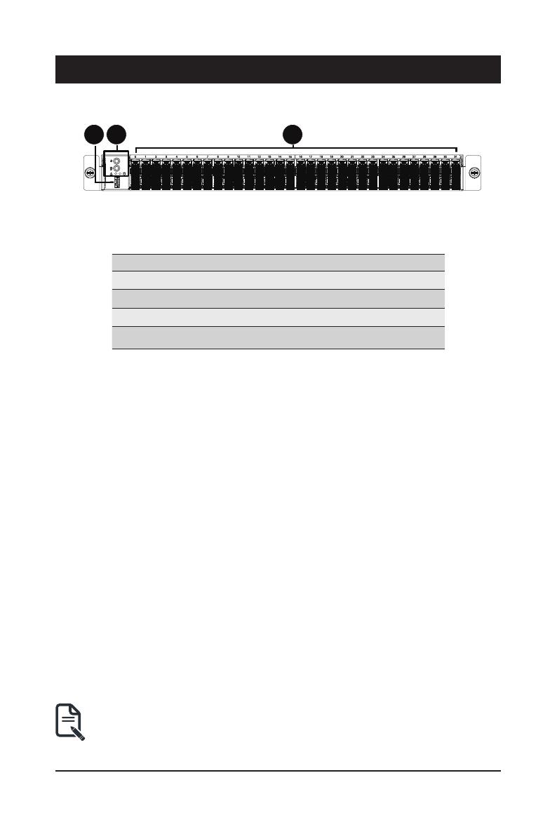
2-1 Front View
No. Description
1. USB 3.2 Gen1 Port
2. Front Panel LEDs and Buttons
3. EDSFF E1.S SSD Bay
Note! Drives with green latches support NVMe.
• Refer to section 2-3 Front Panel LEDs and Buttons for a detailed description of the
function of the LEDs.
1 2 3
E1S0
E1S1
E1S2
E1S3
E1S4
E1S5
E1S6
E1S7
E1S8
E1S9
E1S10
E1S11
E1S12
E1S13
E1S14
E1S15
E1S16
E1S17
E1S18
E1S19
E1S20
E1S21
E1S22
E1S23
E1S24
E1S25
E1S26
E1S27
E1S28
E1S29
E1S30
E1S31

System Appearance
- 17 -
2-2 Rear View
1 2 3 4 65
PSU1PSU2
SLOT2SLOT3
SLOT1
No. Description
1. Mini DP Port
2. USB 3.2 Gen1 Port x 2
3. GbE LAN Port x 2
4. Server Management LAN Port
5. PCIe Card Slot
6. PCIe Card Slot
• Refer to section 2-5 Rear System LAN LEDs for a detailed description of the function of the
LEDs.
- 18 -
System Appearance
(Note) If your server features RoT function, please see the following section for detail LED behavior.
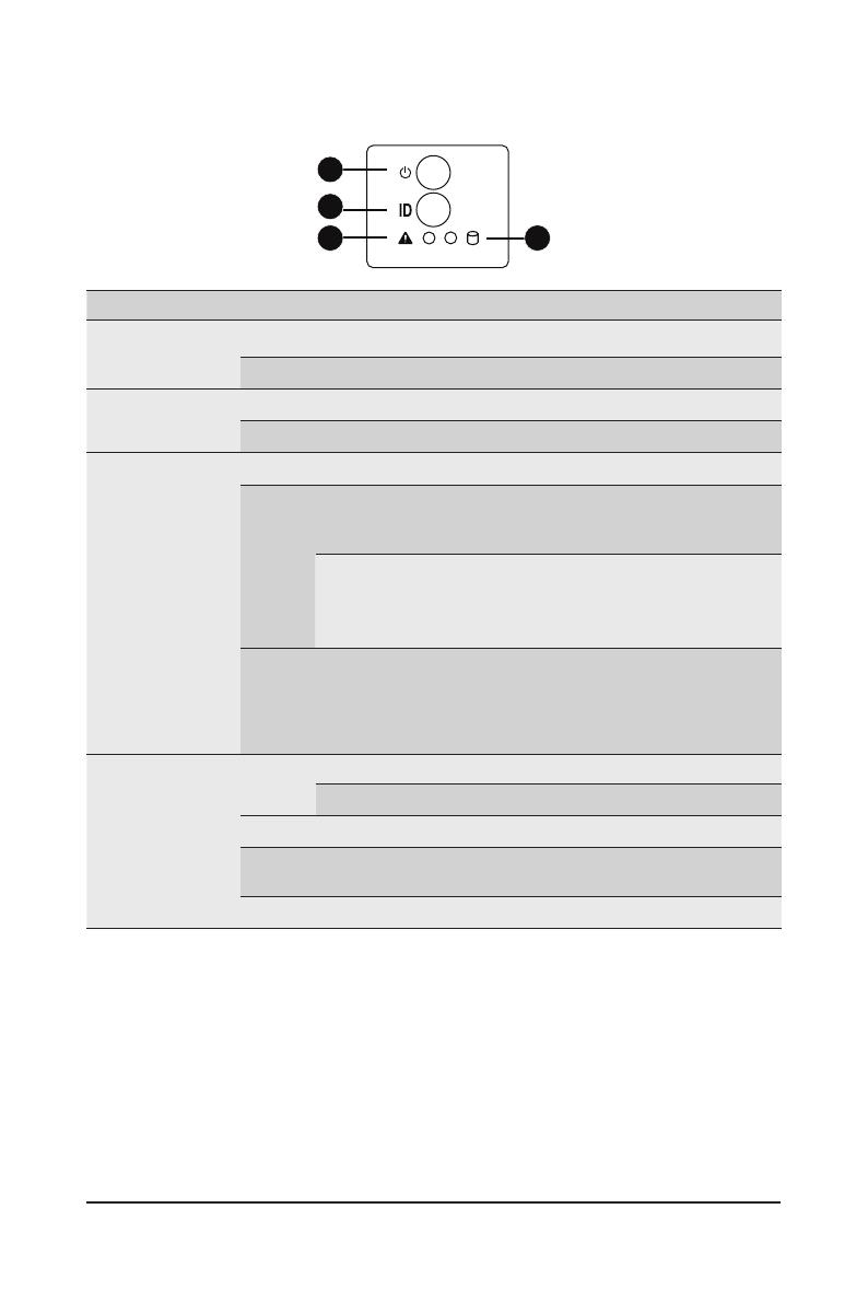
2-3 Front Panel LEDs and Buttons
1
2
3 4
No. Name Color Status Description
1. Power button
with LED
Green On Indicates the system is powered on.
N/A Off System is not powered on or in ACPI S5 state (power off)
2. ID Button with
LED(Note)
Blue On System identication is active.
N/A Off System identication is disabled.
3. System Status
LED(Note)
Green Solid On System is operating normally.
Amber
Solid On
Critical condition, may indicate:
System fan failure
System temperature
Blink
Non-critical condition, may indicate:
Redundant power module failure
Temperature and voltage issue
Chassis intrusion
N/A Off
System is not ready, may indicate:
POST error
NMI error
Processor or terminator missing
4. HDD Status
LED
Green On Indicates locating the HDD.
Blink Indicates accessing the HDD.
Amber On Indicates HDD error.
Green/
Amber Blink Indicates HDD rebuilding.
N/A Off Indicates no HDD access or no HDD error.
- 19 -
System Appearance
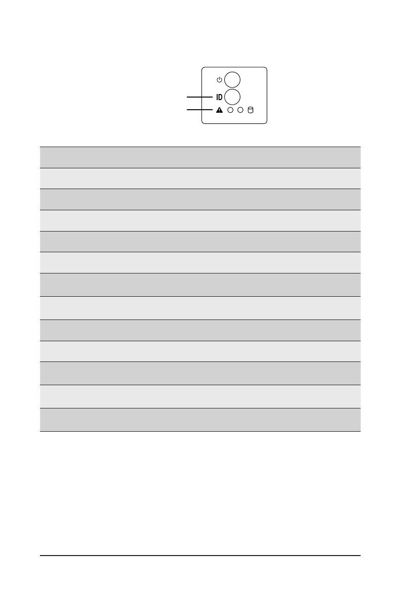
2-4 RoT LEDs
ID LED
Status LE
D
LED on Front panel(Note5)
ID LED Status LED
EC Firmware (FW) Authentication fail or not exit
EC FW is broken or not exit (Note1) OFF OFF
Authenticating/Recovering BMC/BIOS Images
Authenticating Images OFF OFF
Recovering BMC Active Flash Blinks Blue
4 times per second
Blinks Green
4 times per second
Recovering BIOS Active Flash Blinks Blue
4 times per second
Blinks Green
4 times per second
Authentication (AUTH) Pass
Recovering BIOS Active Flash OFF OFF
BMC : AUTH pass after doing recovery
BIOS : AUTH pass after doing recovery OFF OFF
BMC : AUTH pass after doing recovery
BIOS : AUTH pass OFF OFF
BMC : AUTH pass
BIOS : AUTH pass after doing recovery OFF OFF

- 20 -
System Appearance
NOTE!
1. EC FW is broken or not exited result in Microchip CEC1702 cannot load EC FW for authentication.
2 (1) Authentication fail include below scenarios
Conguration table is missing or modied
Public key is missing or modied
Protected area or signature is modied
Flash empty
3. if active ash is still authentication failed after recovery sequence, Microchip CEC1702 stop the process
and showing LED behavior.
4. If backup flash authentication is failed cause by configuration table, public key or protected area is
broken. Microchip CEC1702 stop the process and showing LED behavior.
5. Front panel LED is controlled by BMC or Microchip CEC1702. Once Microchip CEC1702 is working(Auth
or recovery), the front panel LED is controlled by Microchip CEC1702 and vice versa.
Active Flash Authentication (AUTH) Fail
BMC : AUTH Fail(Note2) Blinks Blue
1 time per second
Blinks Green
1 time per second
BIOS : AUTH fail(Note2) Blinks Blue
1 time per second
Blinks Amber
1 time per second
BMC : AUTH fail after doing recovery(Note3)
Blinks Blue
2 times per second
[ON OFF OFF]
Blinks Green
2 times per second
[ON OFF OFF]
BIOS : AUTH fail after doing recovery(Note3)
Blinks Blue
2 times per second
[ON OFF OFF]
Blinks Amber
2 times per second
[ON OFF OFF]
Backup Flash Authentication Fail(Note4)
BMC : AUTH fail
Blinks Blue
2 times per second
[ON OFF ON OFF]
Blinks Green
2 times per second
[ON OFF ON OFF]
BIOS : AUTH fail
Blinks Blue
2 times per second
[ON OFF ON OFF]
Blinks Amber
2 times per second
[ON OFF ON OFF]
/