Page is loading ...

5010-22
1/01
Columbia, SC, USA
Drum Brakes Class 5010, Type F
8-Inch WB Brake, Series A
10-, 13-, 16-, 19-, and 23-Inch WB Brakes, Series C
Frenos de tambor clase 5010,
tipo F
Freno WB de 203 mm, serie A
Frenos WB de 254, 330, 406, 483 y 584 mm,
serie C
Freins à tambour de classe 5010,
type F
Frein WB de 203 mm, série A
Freins WB de 254, 330 , 406, 483 et 584 mm, série C
Instruction Boletín de Directives
Bulletin instrucciones d'utilisation
Retain for future use. / Conservar para uso futuro. / À conserver pour
usage ultérieur.

5010-22 Drum Brakes Class 5010, Type F
1/01 Introduction
3
© 2001 Schneider Electric All Rights Reserved
ENGLISH
The Class 5010 WB brake is a spring-set, electrically released, shoe-type
friction brake. It is designed to meet AISE Standard No. 11 and NEMA
Standard ICS 9 Part 1 for torque rating, wheel diameter, mounting
dimensions, and electrical operating characteristics.
Table 1 shows the maximum brake torque ratings. The torque setting for the
standard brake can be adjusted down to 50% of the maximum rating. A half-
torque spring is available which limits the maximum torque to 50% of the
ratings listed and provides adjustment down to 25% of the ratings listed.
The Class 5010 WB brake, when used with either AC or DC motors, provides
a fixed torque for holding or stopping the drive. The brake is supplied with
either a DC series-wound coil or a DC shunt-wound coil. Shunt-wound
brakes use a partial voltage coil and require connection of a shunt brake
resistor in series with the brake coil. AC applications require a rectifier control
panel (refer to bulletin 5010-16 for details).
DC series-wound coils are designed to release the brake at 40% of rated
motor current and to hold the brake released at 10% of rated motor current.
DC shunt-wound coils are designed to release the brake at 80% of rated
voltage and operate continuously at 110% of rated voltage. For application
information see Tables 2–4.
Table 1: Maximum Brake Torque Rating (lb-ft.)
Brake
Size
(in.)
Series-Wound Brakes Shunt-Wound Brakes
1/2-Hour
Rating
1-Hour
Rating
1-Hour
Rating
8-Hour
Rating
High-Speed and
Rectifier Operated
8 100 65 100 75 100
10 200 130 200 150 200
13 550 365 550 400 550
16 1000 650 1000 750 1000
19 2000 1300 2000 1500 2000
23 4000 2600 4000 3000 4000
INTRODUCTION
HAZARDOUS VOLTAGE
Disconnect all power before servicing this equipment.
Failure to follow this instruction will result in death, serious injury,
or equipment damage.
DANGER
STORED ENERGY HAZARD
• The torque spring is under compression.
• Perform the disassembly and assembly steps in the exact order listed.
Failure to follow these instructions can result in death or serious
injury.
WARNING
SPECIFICATIONS

Drum Brakes Class 5010, Type F 5010-22
Specifications 1/01
© 2001 Schneider Electric All Rights Reserved
4
ENGLISH
Table 2: Application Table for Shunt Brake Coils
Brake Coil
Resistance
@ 20 °C
(Ω)
DC Voltage
Rating (Vdc) Shunt Brake Resistors and Relay for 230 Vdc
1 Hour 8 Hour
1-Hour
Service
Resistor
8-Hour
Service
Resistor
High-Speed
Service
Resistor
High-Speed
Service
Relay
F-0857 50903-132-67 45.0 121 87 Class 5010,
Type RO-125
(50 Ω, 400 W)
Class 5010,
Type RO-126
(100 Ω, 400 W)
Class 5010,
Type RO-127
(400 Ω, 400 W)
Class 7001,
Type KFO-01,
Form F08
F-1077 50904-224-75 64.3 181 119 Class 5010,
Type RO-105
(17.5 Ω, 400 W)
Class 5010,
Type RO-128
(60 Ω, 400 W)
Class 5010,
Type RO-119
(225 Ω, 600 W)
Class 7001,
Type KFO-01,
Form F10
F-1375 50905-224-76 43.2 163 111
Class 5010,
Type RO-106
(20 Ω, 800 W)
Class 5010,
Type RO-111
(45 Ω, 600 W)
Class 5010,
Type RO-148
(150 Ω, 400 W)
Class 7001,
Type KFO-01,
Form F13
F-1674 50906-224-75 23.7 135 94 Class 5010,
Type RO-106
(20 Ω, 800 W)
Class 5010,
Type RO-109
(35 Ω, 800 W)
Class 5010,
Type RO-126
(100 Ω, 400 W)
Class 7001,
Type KFO-01,
Form F16
F-1959 50907-132-68 27.36 169 114
Class 5010,
Type RO-132,
(12.5 Ω, 400 W)
Class 5010,
Type RO-146
(40 Ω, 800 W)
Class 5010,
Type RO-148
(150 Ω, 400 W)
Class 7001,
Type KFO-01,
Form F19
F-2374 50908-251-66 15.1 149 92 Class 5010,
Type RO-136
(10 Ω, 1200 W)
Class 5010,
Type RO-138
(30 Ω, 1200 W)
C lass 5010,
Type RO-116
(100 Ω, 800 W)
Class 7001,
Type KFO-01,
Form F23
Table 3: Application Table for Rectifier-Operated Brake Coils
Brake
Size
(inches)
Brake Coil
Resistance
@ 20 °C
(Ω)
DC Voltage Rating (Vdc)
Rectifier-Operated Application
1 Hour 8 Hour
8F-0853 50903-132-63 7.30 49 35 Single brake coil
F-0851 50903-132-61 2.90 31 22 Two brake coils connected in series
10 F-1072 50904-224-70 6.32 56 37 Single brake coil
F-1070 50904-224-68 2.56 36 24 Two brake coils connected in series
13 F-1370 50905-224-71 4.28 51 35 Single brake coil
F-1385 50905-224-69 1.69 32 22 Two brake coils connected in series
16 F-1670 50906-224-71 3.73 53 37 Single brake coil
F-1686 50906-224-68 0.93 26.8 18.6 Two brake coils connected in series
19 F-1954 50907-132-63 2.83 54.6 36.7 Single brake coil
F-1951 50907-132-60 0.704 27.2 18.3 Two brake coils connected in series
23 F-2383 50908-251-62 2.38 59 36 Single brake coil
F-2384 50908-251-59 0.592 30 18 Two brake coils connected in series

5010-22 Drum Brakes Class 5010, Type F
1/01 Specifications
5
© 2001 Schneider Electric All Rights Reserved
ENGLISH
Table 4: Application Table for Series Brake Coils
Brake
Size
(inches)
Brake Coil
Resistance
@ 20 °C
(Ω)
1/2-Hour Service @ 230 Vdc 1-Hour Service @ 230 Vdc
Ampere
Rating
Horsepower
Rating
Ampere
Rating
Horsepower
Rating
8
F-0809 50903-132-58 0.839 20.5 4.5 16.8 3.5
F-0808 50903-132-57 0.552 25.5 6.0 20.7 4.5
F-0807 50903-132-56 0.369 31.0 7.0 25.4 5.5
F-0806 50903-132-55 0.215 41.0 10.0 33.0 8.0
F-0805 50903-132-54 0.1304 52.5 13.0 42.5 10.5
F-0804 50903-132-53 0.0802 67.0 17.0 54.5 14.0
10
F-1030 50904-224-63 0.453 35.5 8.5 28.0 7.0
F-1027 50904-224-62 0.277 45.4 11.5 35.8 8.5
F-1026 50904-224-61 0.181 56.2 14.0 44.4 11.0
F-1029 50904-224-60 0.115 70.5 18.0 55.6 14.0
F-1025 50904-224-59 0.0713 89.5 23.0 70.6 18.0
F-1028 50904-224-64 0.688 28.8 7.0 22.7 5.0
F-1024 50904-224-58 0.0451 112 30 88.8 23.0
13
F-1326 50905-224-62 0.152 73 19.0 58 15.0
F-1325 50905-224-60 0.0603 115 30.5 93 24.0
F-1324 50905-224-59 0.0381 145 39.0 117 31.0
F-1323 50905-224-58 0.0238 184 49.5 148 40.0
F-1329 50905-224-57 0.01507 230 63.0 186 50.0
F-1321 50905-224-56 0.00943 292 80.0 235 64.0
16
F-1624 50906-224-59 0.033 176 47.0 137 36.0
F-1625 50906-224-58 0.021 222 60.0 173 46.0
F-1623 50906-224-57 0.013 281 77.0 219 59.0
F-1622 50906-224-56 0.0082 354 96.0 277 76.0
F-1621 50906-224-55 0.0051 448 122.0 350 95.0
19
F-1908 50907-132-54 0.0176 283 78.0 217 59.0
F-1907 50907-132-53 0.0107 363 97.0 278 76.0
F-1906 50907-131-56 0.00733 429 120.0 326 90.0
F-1905 50907-131-55 0.00431 560 155.0 426 116.0
F-1904 50907-131-54 0.00332 638 178.0 485 134.0
23
F-2326 50908-252-51 0.0119 379 102.0 299 80.0
F-2325 50908-252-52 0.0094 427 117.0 337 90.0
F-2324 50908-252-53 0.0051 577 160.0 456 127.0
F-2335 50908-252-56 0.0024 845 235.0 669 185.0
F-2322 50908-252-57 0.0013 1155 320.0 913 252.0
F-2321 50908-252-58 0.00098 1316 365.0 1041 290.0
F-2336 50908-252-54 0.0040 651 180.0 515 142.0
F-2323 50908-252-55 0.0031 745 206.0 589 162.0
Note: Contact your local Square D sales office for additional coils.

Drum Brakes Class 5010, Type F 5010-22
Installation 1/01
© 2001 Schneider Electric All Rights Reserved
6
ENGLISH
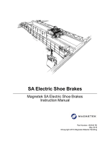
Figure 1: Brake Installation
To locate parts during installation:
• See Figure 1 for parts identified by a letter, e.g., “(G)”
• See Tables 7 through 12 and Figures 6 through 11 for any parts not
referenced by letters.
1. Unpack the brake carefully. Remove the shipping strap securing the
inboard shoe levers to the magnet case.
2. Check nameplate data for correct equipment. Verify that the brake coil is
correct. Refer to Tables 2–4.
3. Verify that all parts are undamaged and secure.
4. Check that the brake wheel size and dimensions are correct (part number
is stamped on the face of the hub).
5. Check that the brake has been manually released by removing the cotter
pin (G) from the manual release nut (F) and tightening the manual release
nut until the armature is completely closed.
6. Mount the brake wheel (R) on the motor shaft and slide the brake into
position, using the lifting ears (Y) on the magnet case. Center the brake
wheel (R) between the shoes (L).
7. If machinery interference prevents the brake from sliding over the end of
the wheel, the brake can be disassembled and moved into position.
a. If the brake is equipped with a self-adjusting shoe mechanism,
disconnect the self-adjusting connecting rod from the crank assembly by
removing the screw, washers, and nut.
b. Relieve compression in the torque spring (D). See “Relieving Torque
Spring Compression” on page 7.
c. Slide the brake into position, using the lifting ears (Y) on the magnet case.
Center the brake wheel (R) between the shoes (L).
d. Tighten the manual release nut (F) against the yoke (E) and
simultaneously lower the overlever assembly (DD). Verify that the flange
on the manual release nut passes through the hole in the yoke and that
the torque spring (D) is seated on the yoke, allowing the overlever
assembly to pass.
e. Replace the connecting rod spring (H). Swing the outboard shoe lever (K)
into position. Replace the stop nut (J).
INSTALLATION
CAUTION
LIFTING HAZARD
Use lifting ears. Do not lift the brake by the
overlever assembly.
Failure to follow this instruction can result
in serious injury or equipment damage.
INSTALLATION HAZARD
Disconnect the self-adjusting connecting rod
from the crank assembly before relieving
compression in the torque spring.
Failure to follow this instruction can result
in equipment damage.
CAUTION

5010-22 Drum Brakes Class 5010, Type F
1/01 Installation
7
© 2001 Schneider Electric All Rights Reserved
ENGLISH
f. If the brake is equipped with a self-adjusting mechanism, reconnect the
self-adjusting connecting rod to the crank assembly using the screw,
washers, and nut.
8. Align the brake so that the shoes (L) are centered on the face of the wheel
and the brake is perpendicular to the motor shaft, both vertically and
horizontally.
9. Mount the brake so that the center of the brake wheel (R) coincides with
the intersection of a horizontal line passing through the centers of the
shoes (L) and a vertical line passing through the hole (S) located on the
side of the brake frame below the wheel. See Figure 2.
Figure 2: Brake Alignment
10. Using customer-supplied hardware, securely fasten the base of the brake
using the four mounting holes (Q). Additional support is not normally
required under the magnet case.
11. Loosen the manual release nut (F) to its original position and secure with
the cotter pin (G).
12. Connect the brake coil leads (refer to the wiring diagram supplied with the
brake).
Use one of the following methods to relieve the torque spring (D):
•Method 1: Loosen the torque adjusting nut (C) until the torque spring is
no longer under compression.
•Method 2: Perform disassembly steps a through d in the order listed.
a. Tighten the manual release nut (F) until the armature is completely
closed.
b. Remove the stop nut (J) from the end of the overlever assembly (DD).
c. Swing the outboard shoe lever (K) down and remove the connecting rod
spring (H).
NOTE: The latch pin assembly can be arranged to allow operation from
either side of the brake, whichever is most convenient.
The brake automatically
adjusts for ±1/4''
misalignment with respect
to the vertical line. The
brake must be accurately
positioned with respect to
the horizontal line.
INSTALLATION HAZARD
The resistor must be connected in series with
the brake coil on shunt-wound brakes.
Overheated coil can result in injury or
equipment damage.
CAUTION
Relieving Torque Spring Compression
DROP OR MOTION HAZARD
Restrain or remove the hoist load or restrain the bridge/trolley from
moving before releasing the brake.
Failure to follow this instruction will result in death or serious injury.
DANGER
STORED ENERGY HAZARD
• The torque spring is under compression.
• Perform the disassembly and assembly
steps in the exact order listed.
Failure to follow these instructions can
result in death or serious injury.
WARNING

Drum Brakes Class 5010, Type F 5010-22
Adjustments 1/01
© 2001 Schneider Electric All Rights Reserved
8
ENGLISH
d. Loosen the manual release nut (F) and simultaneously raise the overlever
assembly (DD), gradually relieving compression in the torque spring (D).
Depress the spring-loaded latch pin (A), allowing the overlever assembly
to pass.
This section describes the adjustment of the armature gap, shoe clearance,
and brake torque. Letters in parentheses refer to Figure 1 on page 6.
The armature gap indicator (T) indicates the minimum and maximum
allowable armature gap setting. It is mounted on the frame near the bottom
of the magnet case (see Figure 3).
Figure 3: Armature Gap Indicator
On brakes not equipped with the self-adjuster, the stop nut (J) at the end of
the overlever assembly adjusts the armature gap. To adjust the armature
gap:
1. Turn the stop nut clockwise to reduce the armature gap.
2. With the brake set, adjust the stop nut so that the armature gap is at the
minimum setting. Use the jam nut (DD) to lock the stop nut (J) in place.
The self-adjusting brakes are designed to work with Square D factory brake
pads only. As the brake shoe wears, brakes equipped with a self-adjuster
automatically adjust to the correct armature gap/shoe clearance operating
gap. When initially setting up the brake, or after maintenance, manually
ADJUSTMENTS
HAZARDOUS VOLTAGE
Disconnect all power before servicing this equipment.
Failure to follow this instruction will result in death or serious
injury.
DANGER
UNINTENDED EQUIPMENT OPERATION
After performing any adjustment, maintenance, or troubleshooting
procedure, visually verify that the manual release nut (F) is backed off to
the original position and is secured with the cotter pin (G).
Unexpected brake release can result in death, serious injury, or
equipment damage.
WARNING
Armature Gap Adjustment
Armature
Magnet
Case
Armature
Gap
Indicator
Min.
Max.
The armature gap
indicator can be
mounted on either side
of the magnet case,
whichever is most
convenient.
Non Self-Adjusting Brakes
Self-Adjusting Brakes

5010-22 Drum Brakes Class 5010, Type F
1/01 Maintenance
9
© 2001 Schneider Electric All Rights Reserved
ENGLISH
adjust the brake to the maximum gap indicated by the armature gap indicator
(T). This allows the brake to adjust to the correct armature gap.
Adjusting the armature gap also adjusts the shoe clearance. With the
armature gap at the minimum setting, shoe clearance between the wheel and
the brake shoe lining (L) is 1/32 in. Brake shoes automatically self-align for a
uniform gap between the shoe and the wheel. Operate the brake and check
for proper shoe clearance.
The brake torque setting is read directly from the torque calibration plate,
mounted next to the operating spring on the yoke.
Be sure that the brake is set before adjusting the brake torque. Adjust the
torque to the desired value by turning the adjusting nut (C). This varies the
length of the operating spring (D). Use the jam nut (B) to lock the adjusting
nut (C) in place.
This section describes items on the brake that may require periodic
maintenance. Inspect these items regularly. The brake is supplied with oil-
impregnated bearings that do not normally require lubrication in most
environments. Grease fittings are available as an option (standard on 19'' and
23'' brakes), and are recommended for brakes used outdoors or in high
temperature environments.
OSHA code requires the inspection of brakes at 1-month to 12-month
intervals, depending on activity, severity of service, and environment of the
brakes. The code specifically lists the following items for inspection:
deformed, cracked, or corroded members; loose bolts; worn, cracked, or
distorted parts. (OSHA code of Federal Regulations Part 1910.179 J2 and
J3.)
Depending upon the application and environment, wearing parts may require
more frequent inspection. It is your responsibility to determine appropriate
inspection intervals.
As linings wear, the armature gap increases. With the brake set, the armature
gap is correct when the inside of the armature aligns with the inside edge of
the slotted step of the armature gap indicator (T). The maximum allowable
gap is indicated by the outside edge of the slotted step of the armature gap
indicator (Figure 3). The stop nut (J) must be readjusted before the armature
gap reaches the maximum allowable limit.
A hex nut (M) on the shoe assembly acts as a gauge to indicate shoe lining
wear. Replace the lining when its wear surface is even with the top edge of
the hex nut (M). Brake shoe removal does not affect the torque setting.
Shoe Clearance
Brake Torque
MAINTENANCE
HAZARDOUS VOLTAGE
Disconnect all power before servicing the equipment.
DROP OR MOTION HAZARD
Restrain or remove the hoist load or restrain the bridge/trolley from
moving before releasing the brake.
Failure to follow these instructions will result in death or serious
injury.
DANGER
Periodic Inspection
Brake Shoe and Lining
Replacement

Drum Brakes Class 5010, Type F 5010-22
Maintenance 1/01
© 2001 Schneider Electric All Rights Reserved
10
ENGLISH
Replace the brake linings using the following procedures (refer to Figure 1):
1. Disconnect power to the brake.
2. Manually release the brake by removing the cotter pin (G) from the
manual release nut (F) and tightening the manual release nut (F) until the
armature is completely closed.
3. Remove the two hex nuts (M), hex-head cap screws (P), and springs (N)
from each shoe.
4. Slide the shoes (L) out from either side of the brake.
NOTE: Linings are riveted. Replacement lining kits are available (refer to
Tables 7 through 12).
5. Replace the shoes, springs, hex-head cap screws, and hex nuts. Tighten
the hex-head cap screws (P) until the spring (N) is fully compressed.
Loosen the hex-head screws as indicated in Table 5 according to the
brake size.
6. Readjust the armature air gap as explained in “Shoe Clearance” on
page 9.
7. Loosen the manual release nut (F) to its original position and secure with
the cotter pin (G).
The coil and coil core are encapsulated. The operating coil is removed from
the rear of the magnet case. When the coil is removed, the brake settings do
not change and the brake does not need to be released. Normally, it is not
necessary to remove the brake to change the coil.
To remove the coil from the magnet case, perform the following steps in the
order listed:
1. Disconnect power to the brake.
2. Disconnect the coil leads.
3. Remove the six hex-head cap screws (V) from the outer edge of the
magnet case cover.
4. Screw two hex-head cap screws (V) into the threaded blind holes in the
magnet case cover. This will break loose the magnet case cover and coil
core assembly from the magnet case. See Figure 4.
5. A lifting hole (X), located on the magnet case cover, aids in removing the
coil assembly. Slide the coil and core assembly out of the magnet case.
Table 5: Loosening the Brake Lining Spring Compression
Brake Size (inches) Number of Screw Turns Required
81-1/2
10 3/4
13 3/4
16 1-1/2
19 1
23 1-1/2
Coil Replacement
HAZARDOUS VOLTAGE
Disconnect power to the brake before working on the brake coil.
Failure to follow this instruction will result in death, serious injury,
or equipment damage.
DANGER
V
VV
W
X
Figure 4: Rear of Magnet Case
Threaded Blind
Hole
Threaded Blind
Hole

5010-22 Drum Brakes Class 5010, Type F
1/01 Maintenance
11
© 2001 Schneider Electric All Rights Reserved
ENGLISH
6. Lay down the magnet case cover and coil assembly with the flat surface
of the coil downward. See Figure 5.
7. Remove the three hex-head cap screws (W) in the center of the magnet
case cover. Remove the terminal shield and the magnet case cover.
8. Remove any residue particles from inside the magnet case, and wipe it
clean.
9. Verify that the part number of the new coil is correct. See the brake coil
application tables on pages 4–5.
10. Place the new coil and coil core so that the back of the coil is horizontal,
with the coil leads extending vertically. See Figure 5.
11. Position the magnet case cover on top of the coil assembly.
12. Replace the terminal shield and secure with three hex-head cap
screws (W).
13. Seal the space between the coil lead bushing and the magnet case cover
with RTV compound, Dow Corning #RTV 732 or equivalent.
14. Using six hex-head cap screws (V), replace the magnet case cover and
the coil/core assembly into the magnet case.
Perform the following steps to remove the brake wheel (R) from the motor
shaft:
1. Disconnect power to the brake.
2. Manually release the brake by removing the cotter pin (G) from the
manual release nut (F) and tightening the manual release nut until the
armature completely closes.
If replacing the brake wheel and motor armature as a unit, disassemble the
brake according to Method 2 of “Relieving Torque Spring Compression” on
page 7.
Replacement of the frame bushings is recommended during a complete
brake overhaul. Remove power to the brake and secure the load before
removing the brake from the crane.
Perform the following steps to replace the frame bushings:
1. Press out the four stainless steel frame bushings.
2. Press in new bushings (use of the pilot device is recommended).
3. Ensure the lever pin rotates freely.
LIFTING HAZARD
Use lifting hole.
Failure to follow this instruction can result in serious injury or
equipment damage.
CAUTION
Figure 5: Coil and Core Assembly
Coil Leads
Flat Surface
DROP OR MOTION HAZARD
Restrain or remove the hoist load or restrain the bridge/trolley from
moving before releasing the brake.
Failure to follow this instruction will result in death or serious injury.
DANGER
Brake Wheel Replacement
F
rame
B
us
hi
ng
R
ep
l
acement
(Used only on Series C, 10'', 13'',
16'', 19'', and 23'' brakes.)

Drum Brakes Class 5010, Type F 5010-22
Disassembly 1/01
© 2001 Schneider Electric All Rights Reserved
12
ENGLISH
This section contains instructions for disassembling the self-adjusting shoe
mechanism, overlever assembly, armature, and connecting rod lever.
Remove power to the brake before performing these operations.
If the brake is equipped with the self-adjusting shoe mechanism, it can be
removed by following step 7a on page 6.
Before removing the overlever assembly, relieve the compression of the
torque spring (D) using either method in “Relieving Torque Spring
Compression” on page 7.
To reassemble the overlever assembly:
1. Simultaneously tighten the manual release nut (F) against the yoke (E)
and lower the overlever assembly.
2. Ensure that the flange on the manual release nut passes through the hole
in the yoke and the torque spring (D) is seated on the yoke, to allow the
overlever assembly to pass.
3. Loosen the manual release nut (F) to its original position and secure with
the cotter pin (G).
To remove the armature and connecting rod lever, or to gain access to the
lower pins and bearings, perform the following steps in the order listed:
1. If the brake is equipped with the self-adjusting mechanism, remove the
self-adjusting connecting rod by removing the hex-head cap screws,
washers, lock washers, and nuts.
2. Relieve the compression in the torque spring (D) using either method in
“Relieving Torque Spring Compression” on page 7.
3. Disconnect the centering bracket (BB) by removing the cotter pins, nuts,
and springs (Z).
4. Remove the locking pin and the armature pin (AA).
5. Remove the locking pin and the inboard shoe pin (CC).
6. Remove the stop nut (J) from the end of the overlever assembly.
7. Lift the armature, inboard shoe assembly, connecting rod lever, and
overlever assembly from the brake.
When supplied, the self-adjusting shoe mechanism automatically
compensates for shoe lining wear. During normal operation, a ratchet type
assembly, coupled to the armature, automatically adjusts the armature gap
as the shoe linings wear. The standard brake is machined so that the self-
adjusting mechanism can be added as a field modification. Refer to the
bulletin furnished with the self-adjusting mechanism kit for detailed
installation instructions. The self-adjusting shoe mechanism does not require
lubrication.
After the initial brake installation or when replacing the brake shoes, adjust
the shoe clearance and the armature gap:
DISASSEMBLY
STORED ENERGY HAZARD
• The torque spring is under compression.
• Perform the disassembly and assembly steps in the exact order listed.
Failure to follow these instructions can result in death or serious
injury.
WARNING
Self-Adjusting Shoe Mechanism
Overlever Assembly
Armature and Connecting
Rod Lever
SELF-ADJUSTING
SHOE MECHANISM

5010-22 Drum Brakes Class 5010, Type F
1/01 Armature Gap Setup for 19 and 23 Inch Brakes Only
13
© 2001 Schneider Electric All Rights Reserved
ENGLISH
Back off the starwheel stop nut located at the end of the overlever assembly,
until the armature gap is at the maximum allowable setting, as indicated by
the armature gap indicator (T). Manually hold the ratchet rod away from the
starwheel nut while making this adjustment. The self-adjuster will
automatically readjust the armature gap/shoe clearance gap to the correct
setting.
To check for proper assembly of the connecting rod and ratchet rod:
1. For proper operation, the length of the connecting rod, as measured
between the centers of the pivot points at the ends of the rod, should
match the length listed in Table 6.
2. Tighten the connecting rod screws to the torque value listed in Table 6.
There must not be any play between the screw head and bearings.
3. With the brake manually released (armature closed), verify that the
location of the top of the ratchet rod relative to the brake connecting rod
is as listed in Table 6. Ensure the spring holds the ratchet rod firmly
against the starwheel stop nut.
4. The ratchet rod must not be tightened snug to the crank assembly.
Tighten the ratchet rod screw completely, then loosen by one-third turn
(0.025'' clearance). Tighten the jam nut.
Set up the brake using one of two armature gaps, normal or wide. The
orientation of the connecting rod positioner in the crank assembly determines
the armature gap setting. When the brake wheel is subject to wide
temperature variations during operating and cool-off periods, the wider
armature gap may be required to maintain a 1/32 in. minimum shoe
clearance.
To adjust a normal armature gap:
1. Disconnect all power.
2. Install the conecting rod positioner with the larger (1/2 in.-13) tapped hole
positioned closest to the crank assembly pivot pin, refer to Figure 10 on
page 23 and Figure 11 on page 25. This sets the lever arm ration to the
minimum position.
When the self-adjuster overtightens (due to low ambient temperature) and
results in an armature gap less than 1/32 in. adjust a wide armature gap.
To adjust a wide armature gap:
1. Disconnect all power.
2. Rotate the connecting rod positioner 180°. This creates a larger lever arm
ratio, resulting in a larger armature operating gap.
Troubleshooting information can be found on page 26.
Table 6: Connecting Rod and Ratchet Rod Assembly Specifications
Brake Size
(inches)
Length of Connecting
Rod (inches)
Torque
(lb-in)
Ratchet Rod Location Above/
Below the Brake Connecting Rod
8 13.20 225 0.13 inches below center line
10 16.56 225 0.13 inches below center line
13 20.60 225 0.12 inches below center line
16 26.50 225 even with the center line
19 32.62 450 0.15 inches below center line
23 37.80 450 0.15 inches below center line
ARMATURE GAP SETUP FOR
19 AND 23 INCH BRAKES ONLY

Drum Brakes Class 5010, Type F 5010-22
Parts Lists 1/01
© 2001 Schneider Electric All Rights Reserved
14
ENGLISH
NOTE: Refer to Figure 6 for the assembly drawing.
Table 7: Parts List for Class 5010 Type F-08•• 8'' WB Brake, Series A
Item
No. Part No. Description Item
No. Part No. Description
1[1] 5/16''-18 x 1'' hex-head cap screw—6 required 41 [1] 5/16'' plain washer—6 required
2 50903-143-01 Magnet case cover 42 50903-404-03 Lining wear indicator—4 required
3[1] 3/8''-16 x 1'' hex-head steel cap screw—3 required 43 50903-401-10 Pin for armature and shoe levers—4 required
4[1] 5/16'' lock washer—6 required 44 50903-129-50 Inboard shoe lever assembly, includes bearings
5[1] 3/8'' plain lock washer—3 required 45 50903-119-50 Connecting rod lever, includes bearings
6 50903-167-01 Terminal shield 46 50903-115-50 Connecting link assembly, includes bearings
7 50903-166-01 Lead bushing—2 required 47 50903-401-12 Pin for connecting link and rod—3 required
8 29206-00430 O-ring 11/16'' (inside diameter) x 1/8'' wide—
2 required
48 50903-139-01 Armature gap indicator
49 [1] 1/4''-20 x 1-1/4'' hex-head steel cap screw
9 51139-094-01 Nameplate 50 [1] 1/4''-20 hex-head steel jam nut—3 required
10 [1] #6 x 3/8'' drive screw—5 required
[3] 50903-809-51
Assorted hardware package, includes:
4 springs (item 16)
2 “E” rings (item 21)
1 spring (item 22)
1 calibration plate (item 27)
2 locking pins (item 33)
2 lining wear indicators (item 42)
1 armature gap indicator (item 48)
2 #6 x 3/8'' drive screws (item 10)
11 [2, 3] 50903-132-•• Operating coil assembly
12 50903-102-50 Base and magnet case assembly
13 50903-121-50 Armature
14 [3] 29005-40201 Bearing—16 required
15 50903-140-50 Centering bracket
16 50901-010-13 Centering bracket & shoe mounting spring—
6 required
18 [1] 5/16''-18 x 1-1/2'' hex-head steel cap screw—
2 required 60 50903-814-51 Self-adjusting shoe mechanism kit (includes items 61-
80)
20 50903-407-04 Latch pin 61 [1] 3/8'' lock washer—3 required
21 29907-02410 E-ring—2 required 62 50903-158-01 Connecting rod
22 50901-010-09 Latch pin spring 63 29013-02120 Connecting rod end bearings—2 required
23 50903-117-50 Connecting rod assembly 64 [1] 3/8''-24 hex-head jam nut—2 required
24 W10045 Spring seat 65 [1] 3/8''-16 x 1'' hex-head steel cap screw—2 required
25 50901-010-12 Operating spring 66 [1] 3/8''-16 hex-head nut
26 50903-137-50 Yoke 67 [1] 3/8'' plain washer
27 50903-141-01 Calibration plate 69 [1] 3/8''-16 x 1-1/4'' hex-head steel cap screw
28 50904-136-50 Manual release nut 70 [1] 3/8''-16 hex-head jam nut—2 required
29 [1] 3/32'' x 1-1/2'' Cotter pin 71 50903-826-50 Crank assembly
30 [1] Sash chain 72 50903-160-01 Ratchet rod
31 50901-010-11 Connecting rod spring 73 50903-415-01 Crank pin
32 50903-401-11 Yoke pin 74 50906-165-50 Ratchet rod end block
33 50903-402-03 Locking pin—9 required 75 21601-24660 3/8''-16 x 2-1/4'' socket head screw
34 [1] 1/4'' plain lock washer—11 required 76 50901-003-01 Spring
35 [1] 1/4''-20 x 1/2'' hex-head steel cap screw—10 required 77 50904-154-50 Star wheel stop nut assembly
36 [3, 4] 50903-101-50 Shoe assembly, includes lining—2 required 78 50904-161-01 Ratchet rod guide
37 [3, 4] 50903-808-51 Shoe lining kit, includes linings and rivets for 2 shoes 79 [1] #10-24 x 3/8'' pan head screw with lock washer —
2 required
38 50903-127-50 Outboard shoe lever assembly, includes bearings
39 50903-411-50 Elastic stop nut and washer assembly 80 29005-3221 Bearing—2 required
40 [1] 5/16''-18 x 1-3/4'' hex-head cap screw—4 required
[1] Standard hardware, listed without a Square D part number, can be obtained from a local hardware supplier.
[2] Include coil part number or nameplate data.
[3] Parts recommended for general maintenance.
[4] Shoes are of a non-asbestos material.
PARTS LISTS

5010-22 Drum Brakes Class 5010, Type F
1/01 Parts Lists
15
© 2001 Schneider Electric All Rights Reserved
ENGLISH
Figure 6: Class 5010 8” WB Brake Assembly
35
1
4
78
6
10 9
2
11
12
43
33
34
35
79
78
77
76
48
33
34
35
34
35
43
72
65
61
64
62
63 69
61
63
64
73
70
71
80
61
66
61
70
75
74
64
67
35 43
14
46
33
34
47
49
50 34 33 47
47
34
35
33
14
13
20
21 22
45
14
14
44
14 42
14
37
36
31
28
29
30
35
34
33
34
35
32
16
40
41
39
38
26
27
10
25
24
14
23
18
41
16
41
15
60
Overlever
Assembly

Drum Brakes Class 5010, Type F 5010-22
Parts Lists 1/01
© 2001 Schneider Electric All Rights Reserved
16
ENGLISH
NOTE: Refer to Figure 7 for the assembly drawing.
Table 8: Parts List for Class 5010 Type F-10•• 10'' WB Brake, Series C
Item
No. Part No. Description Item
No. Part No. Description
1 50904-223-01 Magnet case cover 41 50903-401-01 Pin for armature and shoe levers—2 required
2[1] 5/16''-18 x 1-1/2'' hex-head cap screw—10 required 42 50904-129-50 Inboard shoe lever assembly, includes bearings
3[1] 5/16'' plain lock washer—10 required 43 50904-119-50 Connecting rod lever, includes bearings
4 50904-167-01 Terminal shield 44 50904-115-50 Connecting link assembly, includes bearings
5 50904-166-01 Lead bushing—2 required 45 50903-401-03 Pin for connecting link and rod—3 required
6 29206-00430 O-ring 11/16'' (inside diameter) x 1/8'' wide—
2 required
46 50904-226-01 Armature gap indicator
47 [1] 5/16''-18 x 1/2'' hex-head steel cap screw—2 required
7 51139-094-01 Nameplate 48 [1] 5/16''-18 x 1-1/2'' hex-head steel cap screw
8 21008-06120 #6 x 3/8'' drive screw—5 required 49 [1] 5/16''-18 hex-head steel jam nut
9 [2,3] 50904-224-•• Operating coil assembly 50 [1] 5/8''-11 jam nut—3 required
10 50904-218-50 Base and magnet case assembly
[3] 50903-809-52
Assorted hardware package, includes:
4 springs (item 38)
2 springs (item 14)
2 “E” rings (item 19)
2 locking pins (item 30)
1 calibration plate (item 25)
1 armature gap indicator (item 46)
1 spring (item 20)
4 lining wear indicators (item 40)
2 #6 x 3/8'' drive screws (item 8)
11 50904-215-50 Armature
12 [3] 29005-48240 Bearing—16 required
13 50904-140-50 Centering bracket assembly
14 50901-010-02 Centering bracket spring—2 required
15 [1] 3/8'' plain washer 1'' O.D.—4 required
16 [1] 3/8''-16 x 1-3/4'' hex-head steel cap screw—
2 required
18 50903-407-01 Latch pin 60 50903-814-52 Self-adjusting shoe mechanism kit (includes items
61–80)
19 29907-02410 E-ring—2 required
20 50901-010-09 Latch pin spring 61 [1] 3/8'' lock washer—5 required
21 50904-117-50 Connecting rod assembly (Includes items 12 and
50)
62 50904-516-01 Connecting rod
63 29013-02120 Connecting rod end bearing—2 required
22 W10045 Spring seat 64 [1] 3/8''-24 hex-head jam nut—3 required
23 W10020 Operating spring 65 [1] 3/8''-16 x 1-1/2'' hex-head steel cap screw—2 required,
grade 5
24 50904-137-50 Yoke
25 50904-141-01 Calibration plate 66 [1] 3/8''-16 hex-head nut—2 required
26 50904-136-50 Manual release nut 67 [1] 3/8'' plain washer—4 required
27 [1] 3/32'' x 1-1/2'' Cotter pin 69 [1] 3/8''-16 x 1-1/4'' hex-head steel cap screw
28 50901-010-01 Connecting rod spring 70 [1] 3/8''-16 hex-head jam nut—2 required
29 50903-401-02 Yoke pin 71 50904-515-50 Crank assembly
30 50903-402-01 Locking pin—9 required 72 50904-160-01 Ratchet rod
31 [1] 5/16'' plain lock washer—11 required 73 50903-415-01 Crank pin
32 [1] 5/16''-18 x 3/4'' hex-head steel cap screw—
8 required
74 50906-165-50 Ratchet rod end block
75 21601-24660 3/8''-16 x 2-1/4'' socket head screw
33 [3] 50904-101-50 Shoe assembly, includes lining—2 required 76 50901-003-01 Spring
34 [4] 50903-808-52 Shoe lining kit, includes linings and rivets for 2
shoes
77 50904-154-50 Star wheel stop nut assembly
78 50904-161-01 Ratchet rod guide
35 50904-127-50 Outboard shoe lever assembly, includes bearings 79 [1] #10-24 x 3/8'' pan head screw with lock washer—
2 required
36 50903-411-50 Nut and washer assembly
37 [1] 3/8''-16 x 2-1/4'' hex-head cap screw—4 required 80 [5] 50903-401-27 Base pins—2 required
38 50901-010-03 Shoe mounting spring—4 required 81 [5] 50903-827-02 Frame bushings—4 required
39 [1] 3/8'' plain washer—4 required 82 [5] 24201-12480 Cotter pins—2 required
40 50903-404-04 Lining wear indicator—4 required
[1] Standard hardware, listed without a Square D part number, can be obtained from a local hardware supplier.
[2] Include coil part number or nameplate data.
[3] Parts recommended for general maintenance.
[4] Shoes are of a non-asbestos material.
[5] Used on brakes with bushings in the frame.

5010-22 Drum Brakes Class 5010, Type F
1/01 Parts Lists
17
© 2001 Schneider Electric All Rights Reserved
ENGLISH
Figure 7: Class 5010 10” WB Brake Assembly
2
3
4
56
87
1
16
15 14
15
12
21
13
11
12
9
10
4130
31
32
79
78
77
76
46
31
47
30
31
32 80
30
31
32
45
30
32 31 48 49
31 30 45
50
22 23
8
25
24
27
28
26
29
32 32
31
30
31
20
19
18
19
12
43
12
45
12
44
30
31
32 41 12
42
33
34
40
12 38 37
39
36
50
35
66
61
67
65 63
64
62
60
72
69
63
64
61
67
73
70
64
74
75
71
61
70
66 61
81
80
82
Overlever
Assembly

Drum Brakes Class 5010, Type F 5010-22
Parts Lists 1/01
© 2001 Schneider Electric All Rights Reserved
18
ENGLISH
NOTE: Refer to Figure 8 for the assembly drawing.
Table 9: Parts List for Class 5010 Type F-13•• 13'' WB Brake, Series C
Item
No. Part No. Description Item
No. Part No. Description
1 50905-223-01 Magnet case cover 38 [1] 5/16''-18 x 1-3/4'' hex-head steel cap screw
2[1] 3/8''-16 x 1-3/4'' hex-head steel cap screw—
10 required
39 [1] 5/16''-18 hex-head steel jam nut screw
40 50903-404-01 Lining wear indicator—4 required
3[1] 3/8'' plain lock washer—10 required 41 50903-401-07 Pin for armature and shoe levers—2 required
4 50905-167-01 Terminal shield 42 50905-129-50 Inboard shoe lever assembly, includes bearings
5 50905-168-01 Lead bushing—2 required 43 50905-119-50 Connecting rod lever, includes bearings
6 29206-00550 O-ring 7/8'' (inside diameter) x 1/8'' wide—
2 required
44 50905-115-50 Connecting link assembly, includes bearings
45 50903-401-09 Pin for connecting link and rod—3 required
7 51139-094-01 Nameplate 46 50904-226-01 Armature gap indicator
8 21008-06120 #6 x 3/8'' drive screw—5 required 47 [1] 5/16''-18 x 1/2'' hex-head steel cap screw—2 required
9 [2,4] 50905-224-•• Operating coil assembly 48 [1] 3/8'' plain washer—4 required
10 50905-218-50 Base and magnet case assembly
[3] 50903-809-53
Assorted hardware package, includes:
4 springs (item 14)
1 spring (item 20)
2 “E” rings (item 19)
2 locking pins (item 30)
1 calibration plate (item 25)
1 armature gap indicator (item 46)
4 lining wear indicators (item 40)
2 #6 x 3/8'' drive screws (item 8)
11 50905-215-50 Armature
12 [3] 29005-56404 Bearing—16 required
13 50905-140-50 Centering bracket
14 50901-010-07 Centering bracket and shoe mounting spring—
6 required
15 [1] 3/8'' plain washer 1'' O.D.—4 required
16 [1] 3/8''-16 x 1-3/4'' hex-head steel cap screw—
2 required 60 50903-814-53 Self-adjusting shoe mechanism kit (includes items 61-79)
18 50903-407-03 Latch pin 61 [1] 3/8'' lock washer—5 required
19 29907-03210 E-ring—2 required 62 50905-158-01 Connecting rod
20 50901-010-06 Latch pin spring 63 29013-02120 Connecting rod end bearing—2 required
21 50905-117-50 Connecting rod assembly (Includes items
12 and 80)
64 [1] 3/8''-24 hex-head jam nut—3 required
65 [1] 3/8''-16 x 1-1/2'' hex-head steel cap screw—2 required
22 W13045 Spring seat 66 [1] 3/8''-16 hex-head nut
23 W13020 Operating spring 67 [1] 3/8'' plain washer—2 required
24 50905-137-50 Yoke 70 [1] 3/8''-16 hex-head jam nut—3 required
25 50905-141-01 Calibration plate 71 50905-515-50 Crank assembly
26 50905-136-50 Manual release nut 72 50905-160-01 Ratchet rod
27 [1] 3/32'' x 1-1/2'' Cotter pin 73 50903-415-02 Crank pin
28 50901-010-08 Connecting rod spring 74 50906-165-50 Ratchet rod end block
29 50903-401-08 Yoke pin 75 21601-24660 3/8''-16 x 2-1/4'' socket head screw
30 50903-402-01 Locking pin—9 required 76 50901-003-03 Spring
31 [1] 5/16'' lock washer—11 required 77 50905-154-50 Star wheel stop nut assembly
32 [1] 5/16''-18 x 3/4'' hex-head steel cap screw—
8 required 78 50904-161-01 Ratchet rod guide
79 [1] #10-24 x 3/8'' pan head screw with lock washer—
2 required33 [3, 4] 50905-101-50 Shoe assembly, includes lining—2 required
34 [3, 4] 50903-808-53 Shoe lining kit, includes linings and rivets for 2
shoes
80 [1] 3/4''-10 jam nut—3 required
81 [5] 50903-401-28 Base pins—2 required
35 50905-127-50 Outboard shoe lever assembly, includes bearings 82 [5] 50903-827-03 Frame bushings—4 required
36 50903-411-51 Elastic stop nut and washer assembly 83 [5] 24201-12400 Cotter pin—2 required
37 [1] 3/8''-16 x 2-1/4'' hex-head cap screw—4 required
[1] Standard hardware, listed without a Square D part number, can be obtained from a local hardware supplier.
[2] Include coil part number or nameplate data.
[3] Parts recommended for general maintenance.
[4] Shoes are of a non-asbestos material.
[5] Used on brakes with bushings in the frame.

5010-22 Drum Brakes Class 5010, Type F
1/01 Parts Lists
19
© 2001 Schneider Electric All Rights Reserved
ENGLISH
Figure 8: Class 5010 13” WB Brake Assembly
23
4
561
8
7
9
10
41
30
31
32
79
78
77
46
47
30
81
31
32
12
30
32 31 45
16
15
14 15
13
11
12
80
21
29
22 23
8
25
24
27
28
26
32
31
30
31
32
43
12
42
34
33
20
19
18
45
38
39 31 30 45
12
44
30
31
32
41
12 40
12 14
37
48
36
80
35
32 31
30
81
76
72
70
61
67
63
65
64
62
65
61
63
64
67
73
70
71
61
66
61
70
75
74
64
31
60
82
83
Overlever
Assembly

Drum Brakes Class 5010, Type F 5010-22
Parts Lists 1/01
© 2001 Schneider Electric All Rights Reserved
20
ENGLISH
NOTE: Refer to Figure 9 for the assembly drawing.
Table 10: Parts List for Class 5010 Type F-16•• 16'' WB Brake, Series B
Item
No. Part No. Description Item
No. Part No. Description
1 50906-223-01 Magnet case cover 41 50903-404-02 Lining wear indicator—4 required
2[1] 1/2''-13 x 2'' hex-head cap screw—10 required 43 50903-401-04 Pin for armature and shoe levers—2 required
3[1] 1/2'' plain lock washer—12 required 44 50906-129-50 Inboard shoe lever assembly, includes bearings
4 50906-230-01 Terminal shield 45 50906-119-50 Connecting rod lever, includes bearings
5 50906-166-01 Lead bushing—2 required 46 50906-115-50 Connecting link assembly, includes bearings
6 29206-00665 O-rings 1-13/16'' inside diameter x 1/8'' wide—
2 required
47 50903-401-06 Pin for connecting link and rod—3 required
50 50904-226-01 Armature gap indicator
7 51139-094-01 Nameplate 51 [1] 5/16''-18 x 3/4'' hex-head steel cap screw—2 required
8 21008-06120 #6 x 3/8'' drive screw—5 required 52 [1] 3/8''-16 x 1-1/2'' hex-head steel cap screw
9 [3] 50906-224-•• Operating coil assembly 53 [1] 3/8''-16 hex-head steel jam nut
10 50906-218-50 Base and magnet case assembly 55 [1] 1''-8 jam nut—3 required
11 50906-215-50 Armature
[3] 50903-809-54
Assorted hardware package, includes:
4 springs (item 14)
1 spring (item 20)
2 “E” rings (item 19)
2 locking pins (item 31)
1 calibration plate (item 26)
1 armature gap indicator (item 50)
4 lining wear indicators (item 41)
2 #6 x 3/8'' drive screws (item 8)
12 [3] 29005-66446 Bearing—16 required
13 50906-228-50 Centering bracket assembly
14 50901-010-04 Centering bracket and shoe mounting spring—
6 required
15 [1] 3/8'' plain washer 1'' O.D.—4 required
16 [1] 1/2''-13 x 2-1/2'' hex-head steel cap screw—
2 required
18 50903-407-02 Latch pin 60 50903-814-54 Self-adjusting shoe mechanism kit (includes items 61–80)
19 29907-03210 E-ring—2 required 61 [1] 3/8'' lock washer—4 required
20 50901-010-06 Latch pin spring 62 50906-516-01 Connecting rod
21 50906-117-50 Connecting rod assembly (Includes items 12 and
55)
63 50906-517-51 Connecting rod end bearing—2 required
64 [1] 3/8''-24 hex-head jam nut
23 50903-405-01 Spring seat 65 [1] 3/8''-16 x 2'' hex-head steel cap screw (threaded to head)
24 WB416 Operating spring 66 [1] 3/8''-16 hex-head nut
25 50906-137-50 Yoke 69 [1] 3/8''-16 x 1-1/2'' hex-head steel cap screw grade 5
26 50906-141-01 Calibration plate 70 [1] 3/8''-16 hex-head jam nut—3 required
27 50906-136-50 Manual release nut 71 50906-515-50 Crank assembly
28 [1] 1/8'' x 2'' Cotter pin 72 50906-160-01 Ratchet rod
29 50901-010-05 Connecting rod spring 73 50903-415-03 Crank pin
30 50903-401-05 Yoke pin 74 50906-165-50 Ratchet rod end block, includes bearings
31 50903-402-02 Locking pin—9 required 75 21601-24660 3/8''-16 x 2-1/4'' socket head screw
32 [1] 3/8'' lock washer—9 required 76 50901-003-02 Spring
33 [1] 3/8''-16 x 1'' hex-head steel cap screw—7 required 77 50906-154-50 Star wheel stop nut assembly
34 [3] 50906-101-50 Shoe assembly, includes lining—2 required 78 50906-161-01 Ratchet rod guide
35 [3, 4] 50903-808-54 Shoe lining kit, includes linings and rivets for 2
shoes 79 [1] #10-24 x 1/2'' pan head screw with lock washer—
2 required
36 50906-127-50 Outboard shoe lever assembly, includes bearings 80 [1] 1/2''- 20 hex-head jam nut—2 required
37 50903-411-52 Elastic stop nut and washer assembly 81 [5] 50903-401-29 Base pins—2 required
38 [1] 1/2''-13 x 3-1/4'' hex-head cap screw—4 required 82 [5] 50903-827-04 Frame bushings—4 required
39 [1] 5/16'' lock washer—2 required 83 [5] 24201-16640 Cotter pin—2 required
[1] Standard hardware, listed without a Square D part number, can be obtained from a local hardware supplier.
[2] Include coil part number or nameplate data.
[3] Parts recommended for general maintenance.
[4] Shoes are of a non-asbestos material.
[5] Used on brakes with bushings in the frame.

5010-22 Drum Brakes Class 5010, Type F
1/01 Parts Lists
21
© 2001 Schneider Electric All Rights Reserved
ENGLISH
Figure 9: Class 5010 16” WB Brake Assembly
23
4
56
8
7
1
9
10
43
31
32
33
50
39
51
79
78 77
52
53 3231
65
32
31
47
47
12
31
32
33
81 31
32
33
81
76
72
62
60
63 80
70
61
61
61
65
31
64
69
63
61
80
73
70
71
61
66
70
75
74
11 18
12
19
20
19
12
33
32 31 32 33
30 29
28
27
35
34
12
44
47
45
46
31
32
33
43 12 41
3
14
338
12
37
55
36
26
8
25
24
23
55 21
16 12
13
3
14
3
82
83
Overlever
Assembly
/