Page is loading ...


NV-DVR1104/CD, NV-DVR1108/CD and NV-DVR1116/CD ver. 1.1 - user's manual
All rights reserved © NOVUS Security Sp. z o.o.
2
INFORMATIONS
EMC (89/336/EEC) and LVD (73/23/EEC ) Directives
CE Marking
Our products are manufactured to comply with requirements of following directives and
national regulations implementing the directives:
- Electromagnetic compatibility EMC 89/336/EEC with further amendments.
- Low voltage LVD 73/23/EEC with further amendment. The Directive applies to electrical
equipment designed for use with a voltage rating of between 50VAC and 1000VAC as well as
75VDC and 1500VDC.
WEEE Directive 2002/96/EC
Information on Disposal for Users of Waste Electrical and Electronic Equipment
This appliance is marked according to the European Directive on Waste Electrical and Electronic
Equipment (2002/96/EC) and further amendments. By ensuring this product is disposed of correctly,
you will help to prevent potential negative consequences for the environment and human health, which
could otherwise be caused by inappropriate waste handling of this product.
The symbol on the product, or the documents accompanying the product, indicates that this appliance
may not be treated as household waste. It shall be handed over to the applicable collection point for the
waste electrical and electronic equipment for recycling purpose.
For more information about recycling of this product, please contact your local authorities, your
household waste disposal service or the shop where you purchased the product.
RoHS Directive 2002/95/EC
Concerning for human health protection and friendly environment, we assure that our
products falling under RoHS Directive regulations, regarding the restriction of the use of hazardous
substances in electrical and electronic equipment, were designed and manufactured in compliance with
mentioned regulation. Simultaneously, we claim that our products were tested and do not contain
hazardous substances exceeding limits which could have negative impact on human health or natural
environment.
Information
The device, as a part of professional CCTV system used for surveillance and control, is not designed
for self installation in households by individuals without technical knowledge.
The manufacturer is not responsible for defects and damages resulted from improper or inconsistent
with user’s manual installation of the device in the system.

NV-DVR1104/CD, NV-DVR1108/CD and NV-DVR1116/CD ver. 1.1 - user's manual
All rights reserved © NOVUS Security Sp. z o.o.
3
WARNINGS AND PRECAUTIONS
WARNING!
READ, KEEP AND FOLLOW THESE INSTRUCTIONS. ALL THE SAFETY AND
OPERATING INSTRUCTIONS SHOULD BE READ BEFORE THE PRODUCT IS
OPERATED.
WARNING:
TO REDUCE THE RISK OF FIRE OR ELECTRIC SHOCK DO NOT EXPOSE THIS UNIT TO
RAIN OR MOISTURE IF THIS UNIT IS DESIGNED FOR INDOOR USE ONLY.
WARNING!
USER IS NOT ALLOWED TO DISASSEMBLE THE CASING IF THERE ARE NO USER-
SERVICEABLE PARTS INSIDE THIS UNIT. ONLY AUTHORIZED SERVICE PERSONNEL
MAY OPEN THE UNIT
INSTALLATION AND SERVICING SHOULD ONLY BE DONE BY QUALIFIED SERVICE
PERSONNEL AND CONFORM TO ALL LOCAL REGULATIONS
WARNING!
DIGITAL MULTIPLEXER IS SENSITIVE TO ELECTROSTATIC DISCHARGES THEREFORE IT
SHOULD BE USED IN ACCORDANCE WITH OPERATING AND MAINTENANCE RULES FOR
DEVICES BASED ON CMOS/MOSFET TECHNOLOGY.
INFORMATION
Data included in the following user’s manual is up to date at the time of printing. Novus Security Sp z o.o. holds
exclusive rights to modify this manual. The producer reserves the rights for device specification modification
and change in the design without prior notice.

NV-DVR1104/CD, NV-DVR1108/CD and NV-DVR1116/CD ver. 1.1 - user's manual
All rights reserved © NOVUS Security Sp. z o.o.
4
WARNINGS AND PRECAUTIONS
1. Installation and servicing of
the Multiplexer
should only be carried out by qualified service
personnel and conform to all local regulations.
2. Do not place the Multiplexer in areas where ventilation openings might be blocked or covered.
3. There are no user-serviceable parts inside this unit. Only authorized service personnel may open the
unit. The equipment should be protected from mechanical damage and kept clean at all times.
4. Protect this device from being exposed to dust and moisture. In the event of the Multiplexer coming
into direct contact with water unplug the device immediately and contact qualified service
personnel. Dusty (soiled/dirty) equipment may be the cause of fire and / or electrical shock.
5. Unplug the unit from the outlet before cleaning. This device can be cleaned only with a clean damp
cloth. Try to avoid using chemically active liquid cleaners or aerosol. In the event of strong dirt it is
allowed to use gentle cleaning lotion.
6. Power supply wires as well as signal wires should be fixed in the way that there is no risk of
mechanical damage, Please take extra caution not to overload sockets and extension cords to
prevent from the risk of fire.
7. In order to prevent the unit from damage, video channel and signal wires should be equipped with
appropriate surge protection device conforming to European Union standards. We also advice
utilizing video and data transmission protection.
8. It is not allowed to operate this device in conditions not complying with exploitation requirements
in the range of power supply, relative air humidity or air temperature..
9. Metal objects cannot be put inside the device. It can cause major malfunction and/or damage the
unit. In the event of the above, user should contact service immediately for further assistance.

NV-DVR1104/CD, NV-DVR1108/CD and NV-DVR1116/CD ver. 1.1 - user's manual
All rights reserved © NOVUS Security Sp. z o.o.
5
TABLE OF CONTENTS
1. FOREWORD INFORMATION...........................................................................................................6
1.1 Main characteristics .......................................................................................................................6
1.2 Technical specification ..................................................................................................................7
2. DEVICE POWER UP.......................................................................................................................... 9
2.1 Preparing the equipment for operation.........................................................................................10
2.2 Electric connectors of back panel ...............................................................................................12
2.3 External Devices Connection......................................................................................................13
2.4 HDD Installation........................................................................................................................13
2.4.1 Swappable bay HDD installation .....................................................................................13
2.4.2 Internal HDD installation (inside the Multiplexer).............................................................13
2.5 Device power on and power off ..................................................................................................14
3. FRONT PANEL DESCRIPTION ......................................................................................................15
4. DEVICE MENU .................................................................................................................................17
4.1 System setup ............................................................................................................................18
4.2 Camera setup............................................................................................................................21
4.3 Motion detection.......................................................................... .................................................22
4.4 Recording.................................................................................................................................24
4.5 Alarm setup..............................................................................................................................26
4.6 Event List.................................................................................................................................28
4.7 HDD Management....................................................................................................................29
4.8 Network setup ..........................................................................................................................31
4.9 Firmware update ......................................................................................................................32
4.10 CD/DVD backup .....................................................................................................................33
4.11 Default setup ............................................................................................................................33
5. RECORDING.....................................................................................................................................34
5.1 Manual recording ......................................................................................................................35
5.2 Schedule recording.....................................................................................................................36
6. PLAYBACK .......................................................................................................................................38
6.1 Play time search .........................................................................................................................38
6.2 Event list search .........................................................................................................................40
7. RECORDED DATA BACKUP ..........................................................................................................41
7.1 Flash memory backup.................................................................................................................41
7.2 CD backup .................................................................................................................................42
8. ALARM INPUTS AND OUTPUTS CONNECTIONS FOR EXTERNAL DEVICES.......................44
9. SPEED DOME CAMERAS - CONNECTION AND CONTROL (PTZ)...........................................46
9.1 Novus Speed Dome Camera Connection ......................................................................................46
9.2 Camera Control...........................................................................................................................48
10. IR REMOTE CONTROL.................................................................................................................49
11. KEYBOARD CONTROL.................................................................................................................50
12. NETWORK CONNECTION............................................................................................................51
12.1 Computer hardware requirements .............................................................................................51
12.2 Initiating connection.................................................................................................................52
12.3 User Interface view ..................................................................................................................53
12.4 Display settings........................................................................................................................54
12.4.1 Saving images in "live" mode.........................................................................................55
12.4.2 PTZ camera control in "live" mode.................................................................................56
12.5 Recorded data search................................................................................................................57
12.5.1 Saving images while playback mode ..............................................................................59
12.6 Software settings......................................................................................................................60
12.6.1 Software language and time server settings.....................................................................60
12.6.2 User password and accounts...........................................................................................60
12.6.3 NC Viewer download ....................................................................................................60
12.6.4 IP Setting ......................................................................................................................60
12.6.5 FTP & e-Mail................................................................................................................61
13. BACKUP PLAYBACK.....................................................................................................................62
13.1 View of NC Viewer software window.......................................................................................62
13.2 Flash memory backup playback ................................................................................................63
13.3 Flash memory backup converting to JPEG or AVI format..........................................................64
13.4 Flash memory backup printing..................................................................................................66
13.5 CD backup playback.................................................................................................................67
13.6 CD backup converting to JPEG or AVI format ..........................................................................67
13.7 CD backup printing ..................................................................................................................67
13.8 Playback from HDD withdrawn directly from multiplexer .........................................................67

NV-DVR1104/CD, NV-DVR1108/CD and NV-DVR1116/CD ver. 1.1 - user's manual
All rights reserved © NOVUS Security Sp. z o.o.
6
FOREWORD INFORMATION
1. FOREWORD INFORMATION
1.1 Main characteristics
Operating mode triplex (simultaneous recording, playback and networking);
Operating system based on Linux system;
The possibility of installing two HDDs 3.5’’ IDE, one of them placed in swappable bay;
Real-time display;
Adjustable recording speed up to 100 fps;
M-JPEG compression algorithm with various image quality settings;
Recording resolution:
- 360 x 288,
- 720 x 288
Schedule recording individually adjustable for each day with selection of mode and recording
speed;
Alarm recording function;
Motion detection with defined active areas;
1-channel audio recording;
Immediate access to any recorded data;
PTZ camera control using front panel, remote control and network applet;
The possibility of remote control of NOVUS
®
compact camera with RS-485 standard;
Protocols: Novus-C, Novus-C1, Novus-C2, Novus-D1, Pelco-D;
Fully-compatible with system keyboards series: NV-KBD60 and NV-KBD30;
Files backup available methods: through network, USB port and using CD-RW recorder;
Build-in CD-RW recorder;
Network connection for live monitoring, playback recorded data, alarm event e-mail notification
and backup event files on FTP;
User friendly multi-lingual OSD;
Multi-level password protection;
Covered camera function;
Remote control by means IR controller (included) or system keyboard;

NV-DVR1104/CD, NV-DVR1108/CD and NV-DVR1116/CD ver. 1.1 - user's manual
All rights reserved © NOVUS Security Sp. z o.o.
7
TECHNICAL SPECIFICATION
1.2. Technical Specifications
Operation Mode Triplex (simultaneous: recording, playback, networking)
Video Input 4 x BNC loop-through, 1Vp-p/75 Ohm
Video Output 1 x BNC Main Monitor output (BNC, 1Vp-p/75 Ohm)
Alarm Input 4
Audio Input 1 x RCA
Alarm Output 1 relay alarm output
Compression algorithm MJPEG
Recording Resolution 720 x 288, 360x288
Recording Speed up to 50 fps (720x288) or up to 100 fps (360x288)
Recording mode Continuous, Event (Alarm, Motion detection)
Schedule recording recording mode selection (continuous, event, no recording) adjustable for each hour
of a day
Display Speed Live display, 25 fps for channel
(up to 200 fps for 4 video inputs)
Display Screen Full screen, 4;
Recorded data search By date/time or events ;
Motion detection adjustable zone's size and sensitivity (12x16 grid)
Event log up to 2000 per HDD
Video loss detection Yes
HDD up to 2 HDD's (up to 400GB each), one in HDD swappable bay
Backup
through the network,
through USB port, on USB Flash Memory, using built-in CD-RW recorder, on PC
using NC Viewer software
External ports 1 x RJ-45 - LAN; 1 x RS-485 - for PTZ camera control
PTZ control directly from the device, through the network
PTZ protocols Novus-C, Novus-C1, Novus-C2, Pelco-D
Device control front panel buttons, system keyboard, network
Menu multilingual OSD
Password authorization one password
Auto System Recovery hardware WATCHDOG function
Power Supply 230 VAC
Power consumption approx. 16 VA w/o HDD, approx. 40VA with 1 HDD, approx. 50 VA with 2 HDD's
Weight 7 kg
Operating temperature 0°C~ +40°C
Operating relative humidity 0%~80% (without condensation)
NV-DVR1104/CD

NV-DVR1104/CD, NV-DVR1108/CD and NV-DVR1116/CD ver. 1.1 - user's manual
All rights reserved © NOVUS Security Sp. z o.o.
8
TECHNICAL SPECIFICATION
Operation Mode Triplex (simultaneous: recording, playback, networking)
Video Input 8 x BNC loop-through,
1Vp-p/75 Ohm
Video Output
1 x BNC Main Monitor output (BNC, 1Vp-p/75 Ohm),
1 x S-Video Main Monitor output,
1 x BNC Spot Monitor output (BNC, 1Vp-p/75 Ohm),
Alarm Input 8
Audio Input 1 x RCA
Alarm Output 1 relay alarm output
Compression algorithm MJPEG;
Recording Resolution 720 x 288, 360x288
Recording Speed up to 50 fps (720x576) or up to 100 fps (360x288)
Recording mode Continuous, Event (Alarm, Motion detection)
Schedule recording recording mode selection (continuous, event, no recording) adjustable for each hour
of a day
Display Speed live display, 25 fps for channel
(up 200 fps for 8 video inputs)
Display Screen Full screen, 4,8, sequence
Recorded data search By date/time or events
Motion detection adjustable zone's size and sensitivity (12x16 grid)
Event log up to 2000 per HDD
Video loss detection Yes
HDD up to 2 HDD's (up to 400GB each), one in HDD swappable bay
Backup
through the network,
through USB port, on USB Flash Memory, using built-in CD-RW recorder, on PC
using NC Viewer software
External ports 1 x RJ-45 - LAN; 1 x RS-485 - for PTZ camera control
PTZ control directly from the device, through the network
PTZ protocols Novus-C, Novus-C1, Novus-C2, Pelco-D;
Device control front panel buttons, system keyboard, network
Menu multilingual OSD
Password authorization one password
Auto System Recovery hardware WATCHDOG function
Power Supply 230 VAC
Power consumption approx. 16 VA w/o HDD, approx. 40VA with 1 HDD, approx. 50 VA with 2 HDD's
Weight 7 kg
Operating temperature 0°C~ +40°C;
Operating relative humidity 0%~80~(without condensation)
16 x BNC loop-through,
1Vp-p/75 Ohm
16
live display, 25 fps for channel
(do 400 fps for 16 video inputs)
NV-DVR1108/CD NV-DVR1116/CD
Full screen, 4,9,13,16, sequence

NV-DVR1104/CD, NV-DVR1108/CD and NV-DVR1116/CD ver. 1.1 - user's manual
All rights reserved © NOVUS Security Sp. z o.o.
9
DEVICE POWER UP
2. DEVICE POWER UP
2.1 Preparing equipment for operation
Please take extra caution when unpacking the device.
Please ensure that following items are included in the package:
If the equipment has been damaged during transport, the contents of package should be packed back to
the original box. Contact the supplier for further assistance.
WARNING !
It is not allowed to power on the equipment directly after it has been brought from a place of low
temperature. If the device has been brought from the area of lower temperature the user should
wait until the equipment warms up slowly and reaches the room temperature.
Condensation of moisturized air may cause short circuit and damage the device.
Power Supply
Cord
HDD Swappable Bay
lock-keys
Digital Multiplexer NV-DVR1104/CD, NV-DVR1108/CD or NV-DVR1116/CD
Net cross-over cable
for Multiplexer-PC connection
CD containing manual and
software
Alarm input terminal
RS-485 terminal
(NV-DVR1108/CD
or NV-DVR1116/CD only)
Remote controller
User’s Manual
NV- D VR 1 10 4 N ET
NV- D VR 1 10 9 N ET
N V- DV R 1 11 6 N E T
u s e r ' s m a n u a l

NV-DVR1104/CD, NV-DVR1108/CD and NV-DVR1116/CD ver. 1.1 - user's manual
All rights reserved © NOVUS Security Sp. z o.o.
10
DEVICE POWER UP
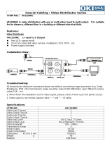
2.2 Electric connectors on back panel of the multiplexers.
1. Audio in: 1 x RCA audio recording input;
2. Audio out : RCA audio output;
3. SPOT: video output for spot monitor connection, only full screen display available;
4. MONITOR OUT: main monitor connection (1 x BNC and 1 x S-Video connectors available);
the possibility of selection from various display modes
5. ALARM: alarm inputs, alarm outputs;
6. RS-232/485: D-Sub 9 PIN connector, for device remote control and PTZ camera control;
7. cooling fan (do not cover!);
8. POWER ~90~260V : Power supply socket;
9. 75Ω / ∞: video inputs termination switch;
10. VIDEO INPUT: video inputs for camera connection;
11. VIDEO OUTPUT: loop-through video outputs;
12. Ethernet: RJ-45 socket for net computer connection;
2 1 3 4 5 6 7 8
10 12 11
2 1 3 4 5 6 7 8
10 12 11
NV-DVR1108/CD
NV-DVR1116/CD
9
9

NV-DVR1104/CD, NV-DVR1108/CD and NV-DVR1116/CD ver. 1.1 - user's manual
All rights reserved © NOVUS Security Sp. z o.o.
11
DEVICE POWER UP
1. CAMERA OUT: loop-through video outputs;
2. MONITOR OUT: main monitor connection (1 x BNC and 1 x S-Video connectors available);
the possibility of selection from various display modes;
3. Audio out : RCA audio output;
4. cooling fan (do not cover!);
5. POWER ~90~260V : Power supply socket;
6. ALARM,RS-232/485: alarm inputs, alarm outputs, remote control and PTZ camera control terminal;
7. Audio in: 1 x RCA audio recording input;
8. CAMERA IN: video inputs for camera connection;
9. Ethernet: RJ-45 socket for net computer connection;
NV-DVR1104/CD
1 2 3
6
4 5
7 9 8

NV-DVR1104/CD, NV-DVR1108/CD and NV-DVR1116/CD ver. 1.1 - user's manual
All rights reserved © NOVUS Security Sp. z o.o.
12
2.3 External Devices Connection
All installation procedures should be conducted by qualified personnel.
Before device installation and operation please analyze the scheme shown below. Depending on
specific user needs and requirements each system will consist of various number of external devices.
DEVICE POWER UP

NV-DVR1104/CD, NV-DVR1108/CD and NV-DVR1116/CD ver. 1.1 - user's manual
All rights reserved © NOVUS Security Sp. z o.o.
13
2.4 HDD Installation
NV-DVR1104/CD, NV-DVR1108/CD and NV-DVR1116/CD digital multiplexers allows to install
two HDD's: one disk installed inside the device and the other one placed in swappable bay.
NOTICE: Producer advices utilizing HDD's manufactured by Hitachi.
Max. allowed capacity of single HDD is 400GB.
WARNING: Producer strongly advices against utilizing Samsung or Western Digital HDD's.
Novus does not take any responsibility for problems caused by using improper
HDD.
Before installing HDD please make sure that jumpers are set properly!
When using only one HDD it must be set in MASTER mode. When using two HDD's, one of them
must be set in MASTER mode and the second in SLAVE mode. HDD configuration, of specified type
and manufacturer, is described in the HDD manual supplied with the HDD.
WARNING: Take into consideration that in case of using HDD from other device (other
multiplexer or PC) while first multiplexer activating all data from HDD will be
erased.
2.4.1 Swappable bay HDD installation
Before installation disconnect power supply cord.
Place the properly set HDD in swappable bay and then screw it on to the casing utilizing 4 supplied
screws. Place the swappable bay in the multiplexer and close it with the key, attached in the package.
2.4.2 Internal HDD installation (inside the DVR)
NOTICE:
Internal HDD should be installed by qualified service personnel.
If the Multiplexer housing is opened by unqualified person the warranty is voided.
DEVICE POWER UP

NV-DVR1104/CD, NV-DVR1108/CD and NV-DVR1116/CD ver. 1.1 - user's manual
All rights reserved © NOVUS Security Sp. z o.o.
14
DEVICE POWER UP
2.5 Device turn on and turn off.
Before turning on the device please make sure that the power supply (voltage and frequency)
conforms to device requirements. Also make sure that the power switch is set to „0”, HDD swappable
bay is locked with the key and that the all external devices are connected properly.
WARNING: We do not advice to connect any additional devices (such us cameras, monitors,
etc..) while device operation.
Device power on is activated by switching the power switch to position „1”.
The loading procedure of the operating system takes about 30 seconds.
During this procedure various information will appear on the screen.
During this procedure please do not press any buttons on the front panel of this device.
The loading procedure is finished when camera images will appear on the Main monitor along with
their descriptions and the system time.
To power off the device stop the recording and shut down the device using power switch.

NV-DVR1104/CD, NV-DVR1108/CD and NV-DVR1116/CD ver. 1.1 - user's manual
All rights reserved © NOVUS Security Sp. z o.o.
15
FRONT PANEL DESCRIPTION
1. Displayed channel selection;
2. AUTO pressing AUTO button activates sequential display mode on Main monitor;
3. SEL Channel selection; each additional press of this button toggles between various,
available display formats ;
4. Toggles between different display formats;
In setting mode these buttons are used as a cursor buttons;
In PTZ mode these buttons are used to control the camera;
ENTER in setting mode is used to enter submenu and edition bars ;
COPY in playback mode activates backup procedure on flash memory;
5. HDD swappable bay;
6. CD-RW recorder;
7. IR receiver; LED's;
8. MENU On Screen Display menu activating;
9. Playback control buttons;
in PTZ mode some buttons are used for camera control;
10. REC manual recording activating/ deactivating (inactive in schedule recording mode);
11. USB port for flash memory card connection;
3. Front Panel Description
1
6
5
9 10
4
8
2 3
11
NV-DVR1108/CD
NV-DVR1116/CD
7
1
6
5
9 10
4
8
2 3
11 7

NV-DVR1104/CD, NV-DVR1108/CD and NV-DVR1116/CD ver. 1.1 - user's manual
All rights reserved © NOVUS Security Sp. z o.o.
16
FRONT PANEL DESCRIPTION
1. Displayed channel or quad selection;
2. Cursor buttons;
In PTZ mode these buttons are used to control the camera;
ENTER in setting mode is used to enter submenu and edition bars ;
COPY in playback mode activates backup procedure on flash memory;
3. IR receiver;
4. HDD swappable bay;
5. CD-RW recorder;
6. LED's;
7. MENU On Screen Display menu activating;
8. Playback control buttons;
in PTZ mode some buttons are used for camera control;
9. REC manual recording activating/ deactivating (inactive in schedule recording mode);
10. USB port for flash memory connection;
NV-DVR1104/CD 1
5
4
8 9
2
7 10 6
3

NV-DVR1104/CD, NV-DVR1108/CD and NV-DVR1116/CD ver. 1.1 - user's manual
All rights reserved © NOVUS Security Sp. z o.o.
17
URUCHOMIENIE URZĄDZENIA DEVICE MENU
4. DEVICE MENU
NV-DVR1104/CD, NV-DVR1108/CD and NV-DVR1116/CD digital multiplexers are equipped with
multi level OSD (on screen display) sub-menus. This menus are used to program settings and to exe-
cute functions such us playback or copying
In order to enter device menu press MENU button.
Main menu consists of 11 submenus. The contents of sub-menus are described on following pages
of this manual.
These buttons are used to select menu items.
Submenus with the possibility of entry are marked with symbol
[
]
ENTER button is used for selection approval, entry to submenu or to edition bar. After entering
edition bar the contents will be highlighted with yellow color.
To modify selected value use buttons .
Exiting the menu accepts and saves inputted modifications.
in some cases system restart is required (system massage will be displayed)
In order to exit selected menu or to return to the higher level menu from individual sub-menus and
modification fields EXIT option should be selected and ENTER button must be pressed. Pressing
MENU button acts similar to the procedures described above. .
NOTICE: In case factory default OSD language is different than English press MENU button, select
first menu item, press ENTER, select 1th menu item and choose desired language, exit from menu.
An example below shows changing language from Polish to English.
▪ SYSTEM SET [
]
▪ CAMERA SET [
]
▪ MOTION SET [
]
▪ RECORD SET [
]
▪ ALARM SET [
]
▪ EVENT LIST [
]
▪ HDD MANAGEMENT [
]
▪ NETWORK SET [
]
▪ FIRMWARE UPDATE [
]
▪ CD/DVD BACKUP [
]
▪ LOAD DEFAULT
▪ EXIT
SETUP MODE
ENTER -SET
MENU EXIT
▪ SYSTEM [
]
▪ KAMERY [
]
▪ DETEKCJA RUCHU [
]
▪ NAGRYWANIE [
]
▪ ALARMY [
]
▪ REJESTR ZDARZEN [
]
▪ DYSKI [
]
▪ USTAWIENIA SIECIOWE [
]
▪ OPROGRAMOWANIE [
]
▪ KOPIOWANIE [
]
▪ USTAWIENIA FABRYCZNE
▪ WYJSCIE
MENU
ENTER - WEJDZ
- ZMIANY MENU - WYJDZ
▪ FORMAT DATY R-M-D
▪ DATA 2006/06/10
▪ CZAS G:M:S 10:10:10
▪ CZAS SEKWENCJI 02S
▪ MONITOR POMOCNICZY
▪ WYSW. DATY/CZASU TAK
▪ SYSTEM WIDEO PAL
▪ BLOKADA PRZYCISKOW WYL
▪ ADRES DVR 01
▪ JEZYK ENGLISH
▪ HASLO DOSTEPU TAK
▪ HASLO 1111
▪ WYJSCIE
MENU SYSTEMOWE 0F0GBD N3.12
ENTER - WEJDZ
- WYBOR
- ZMIANY MENU - WYJDZ

NV-DVR1104/CD, NV-DVR1108/CD and NV-DVR1116/CD ver. 1.1 - user's manual
All rights reserved © NOVUS Security Sp. z o.o.
18
4.1 System setup
Utilizing SYSTEM SETUP menu following system settings may be applied:
(1) DATE FORMAT one of three date formats available can be selected (displayed)0,,
Y– year, M- month, D- day;
(2) DATE date setting;
(3) TIME time setting;
When multiplexer is network connected and all settings are executed there is possibility of manual time
synchronization between the multiplexer and standard time server (NTP protocol). Enter time setting
field and press 1 button for approximately 3 seconds. Following massage will be displayed:
[CAUTION]
WILL BE SYNCHRONIZED WITH NTP
ARE YOU SURE?
▪ YES ▪ NO
If YES is selected system time will be synchronized.
(4) SEQUENCE TIME display time of each camera in sequence mode on Main
monitor, time is defined in seconds (2-99s range)
(5) SPOT MONITOR when this option is selected and ENTER button is pressed
spot monitor submenu is displayed;
CAUTION: only full screen display mode is available on spot monitor (divided screen is unavailable).
On Split monitor there are no descriptions displayed (camera name, system time, etc.) DVR software
version information is displayed on the yellow background.
DEVICE MENU
▪ DATE FORMAT Y-M-D
▪ DATE 2006/06/10
▪ TIME H:M:S 10:10:10
▪ AUTO SWITH DWELL 02 SEC
▪ SPOT SETUP [
]
▪ DATE AND OSD DISPLAY ENABLE
▪ SYSTEM TYPE PAL
▪ KEYBOARD LOCK OFF
▪ ID NUMBER 01
▪ LANGUAGE SELECT ENGLISH
▪ PASSWORD MODE ENABLE
▪ PASSWORD 1111
▪ EXIT
SYSTEM SETUP 0F0GBD N3.12
ENTER -SET
MENU EXIT

NV-DVR1104/CD, NV-DVR1108/CD and NV-DVR1116/CD ver. 1.1 - user's manual
All rights reserved © NOVUS Security Sp. z o.o.
19
in order to activate sequence mode on spot monitor SPOT SWITCHING position should be set
to ON.
When sequence mode is active, display time can be settled individually for each camera in seconds
( 1 to99). If camera is set to OFF image from this camera automatically will not be displayed in
sequence mode.
CAUTION: camera image, which is displayed in sequence mode on spot monitor, can be a bit
brightened on main monitor. Therefore it is recommended to turn off sequence mode when the spot
monitor is unused.
When motion detection and alarm inputs are active automatic sequence mode is aborted for the event
duration. in his time only alarm camera will be displayed. Displaying time depends on alarm settings.
If SPOT SWITCHING position is set to ON, the last selected or last alarm camera from main monitor
will be displayed on spot monitor (when motion detection or alarm inputs are active)
(6) TIME DISPLAY if this option is set to ON time/date information will be
displayed on the main screen;
(9) SYSTEM SELECT This option is used to select TV system standard. PAL or
NTSC system can be selected.
DEVICE MENU
▪ SPOT SWITCHING ON
▪ CAM01 02SEC ▪ CAM09 02SEC
▪ CAM02 02SEC ▪ CAM10 02SEC
▪ CAM03 02SEC ▪ CAM11 02SEC
▪ CAM04 02SEC ▪ CAM12 02SEC
▪ CAM05 02SEC ▪ CAM13 02SEC
▪ CAM06 02SEC ▪ CAM14 02SEC
▪ CAM07 02SEC ▪ CAM15 02SEC
▪ CAM08 02SEC ▪ CAM16 02SEC
▪ EXIT
SPOT SETUP
ENTER -SET
MENU EXIT

NV-DVR1104/CD, NV-DVR1108/CD and NV-DVR1116/CD ver. 1.1 - user's manual
All rights reserved © NOVUS Security Sp. z o.o.
20
(8) KEY LOCK this position is used to select multiplexer access protection
mode. Together with system password it limits (reduces) access
to selected functions. When TYPE 1 is selected after exiting
main menu, recording and playback functions are unavailable
from the front panel. When TYPE 2 is selected after exiting
main menu, all front panel buttons are blocked except for
MENU button. Key lock is deactivated when OFF is selected
(9) DVR ID NUMBER this option enables to establish DVR ID, which is necessary for
multiplexer remote control, using system keyboards:
NV-KBD30 i NV-KBD60. ID number should be selected using
1 to 9 digits. System keyboard connection is described in 11
unit. Keyboard user’s manual is attached to the keyboard set.
(10) LANGUAGE OSD language selection
(11) ACCESS PASSWORD if this option is set to ON, access password is required when
entering main menu. Additional menu line appears below;
PASSWORD This option is used to set a 4 digit password
CAUTION: factory default password is: 1111. please do not forget your new selected password.
In order to recover forgotten password, service help is indispensable.
When Password checking function is active, each MENU button press will generate following system
window. Use cursor buttons to introduce any password changes.
DEVICE MENU
INPUT PASSWORD: 1111
PASSWORD CHECK
ENTER -SET
EXIT
/