
Waterco Limited ABN 62 002 070 733
OFFICES - AUSTRALIA
NSW - Sydney
(HEAD OFFICE)
Tel : +61 2 9898 8686
VIC/ TAS - Melbourne
Tel : +61 3 9879 5141
WA - Perth
Tel : +61 8 9273 1900
QLD - Brisbane
Tel : +61 7 3299 9900
SA/ NT - Adelaide
Tel : +61 8 8244 6000
ACT Distributor
Tel : +61 2 6280 6476
OFFICES - OVERSEAS
Waterco (USA) Inc
Phoenix, Arizona, USA
Tel : +1 623 434 4703
Waterco USA (Baker Hydro)
Augusta, USA
Tel : +1 706 793 7291
Waterco Canada (Focus Temp)
Quebec, Canada
Tel : +1 450 796 4333
Waterco (Europe) Limited
Radfield, Kent, UK
Tel : +44(0) 1795 521 733
Waterco (NZ) Limited
Auckland, New Zealand
Tel : +64 9 525 7570
Waterco (GZ) Limited
Guangzhou, China
Tel : +8620 8335 1107
Waterco (Far East) Limited
Kuala Lumpur
Tel : +60 3 6250 8169
PT Waterco Indonesia
Jakarta, Indonesia
Tel : +62 21 4585 1481
(72515041) 01/2006
www.waterco.com
Notice to Installer
This manual contains important information about the installation, operation
and safe use of this product. Once the product has been installed this manual
must be given to the owner/ operator of this equipment.
This equipment must be installed and serviced by a qualified technician.
Improper installation can create electrical hazards which could result in property
damage, serious injury or death. Improper installation will void the warranty.
WARNING
!
Owners Manual
W7, S14, WPS4, WPS9, MB6,
FS40, CF6 & CU40 Series
Whole of House
Filters, Softeners
and Purifiers

Table of
Waterco Commandomatic I pg 01
GENERAL INFORMATION -------------------------------------------------- 01
COMMANDOMATIC HOME SOLUTIONS ------------------------------- 02
COMMANDOMATIC SEDIMENT FILTER ------------------------------- 03
COMMANDOMATIC WATER SOFTENER/ ----------------------------- 03
PURIFIER SYSTEMS
INSTALLATION INSTRUCTIONS ----------------------------------------- 04
CHECKLIST --------------------------------------------------------------------- 04
CONNECTIONS ---------------------------------------------------------------- 05
INITIAL OPERATION --------------------------------------------------------- 05
WHEN AND HOW TO REGENERATE OR BACKWASH ------------ 06
SOFTENER AND SOFTENER/ PURIFIER REGENERATION ------ 06
UNIT CAPACITY CHART FOR COMMANDOMATIC MODELS ---- 06
SEMI-AUTOMATIC UNIT REGENERATION ---------------------------- 07
FILTER BACKWASH --------------------------------------------------------- 07
COMMANDOMATIC AUTOMATIC CONTROLLER ------------------- 08
PROGRAMMING THE CONTROLLER ----------------------------------- 08
CONTROLLER DISPLAYS -------------------------------------------------- 10
ADDITIONAL DISPLAYS AND SERVICE MENUS -------------------- 10
REPLACING THE A10 VALVE AND CLEANING ---------------------- 11
THE FILTER BED
TROUBLESHOOTING GUIDE ---------------------------------------------- 12
COMMANDOMATIC MEDIA CAPACITIES ------------------------------ 12
SERVICE AND MAINTENANCE INFORMATION ---------------------- 13
COMMANDOMATIC WARRANTY ----------------------------------------- 13
INTRODUCTION
This booklet is designed to cover the total range of Waterco Commandomatic domestic water softeners, puriers
and lters.
GENERAL INFORMATION
Commandomatic domestic units may be divided broadly into two types:-
1. Water Filters
a) Sediment Filters are used to remove suspended material from the water.
Sediment, mud and algae are ltered out down to the size of approximately
10 microns by a lter bed of anthracite, sand and gravel.
b) Carbon Filters contain a deep bed of activated carbon as the lter media.
Carbon is a highly adsorbent material with a very high capacity for the
removal of tastes/ odours, chlorine and Trihalomethanes.
2. Water Softeners and Purier
a) Water Softeners remove hardness ( Calcium and Magnesium ) from water.
The hardness minerals are trapped by the ion exchange resin bed.
b) Purier Softeners are a combination unit. They have both softening and purifying
resins in their resin beds. This unit is well suited to use on water that is moderately
hard and has an organic content.

Waterco Commandomatic
I pg 03
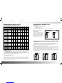
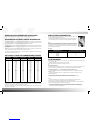
RECOMMENDED UNIT SOFTENER PURIFIER/ SOFTENER SEDIMENT FILTER CARBON FILTER
Number of persons in Household* 1-6 7-9 1-6 7-9 1-6 7-9 1-6 7-9
Commandomatic Model
W7(A) S14(A) WPS4(A) WPS9(A) MB6(A) FS40(A) CF6(A) CU40(A)
TYPICAL
SYMPTOMS
PROBLEM
Hard Water
Soap will not lather
White scale build up
Glass ware streaked
Hardness
Hardness
Hardness
Dirty Water
Dirt/ rust settling out
Sludge/ clay settling
Green organic matter
Sediment
Mud
Algae
Suspended matter Colloidal clay Clarification on Application
Orange/ Brown
Green stains on fittings
Discoloured water
Iron
Copper
Organic colour
Taste and Odour
Smell of chlorine
Rotten vegetable smells
Rotten egg smell
Chlorine
Odour
Hydrongen Sulphide
Salty to taste
Salty/ Brackish
Reverse Osmosis on Application
Other
Not readily detectable
Requires analysis
Fluoride
Nitrate
2
1
1
1
2 2 2
33
1
1
1
1
1
1
1
1
1
COMMANDOMATIC SEDIMENT FILTER
Each unit comprises of:
Pressure vessel containing a mixed bed of either:
a) Anthracite, Sand and Gravel.
b) Activated Carbon.
A10 valve, which directs the ow of water through the cycle of backwash and service.
COMMANDOMATIC HOME SOLUTIONS
Refer to the chart below to nd the unit that best suits the problem.
1. Based on 143mg/L hardness for softeners, Puriers/ Softeners.
2. Water softener satisfactory to 0.3mg/L.
3. Water Purier/ Softener satisfactory to 0.1ppm.
This chart has been prepared as a guide based on municipal water supplies. These products are not designed
for the removal of microorganisms and some may result in the accumulation of them in certain circumstances.
Therefore, for drinking water, it is important that they are used on microbiologically safe water and that ushing
and maintenance protocols are strictly adhered to.
Excellent Performance
Good Performance
Fair Performance
Washing machines, dishwashing machines, spa baths - each count as one person.
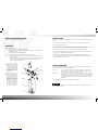
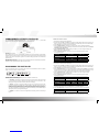
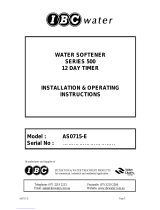
How does a Commandomatic Sediment/
Carbon Filter work?
The filter media is held within a cylinder.
The lter media sits on top of a gravel
bed and a centre tube passes through the
media. Normal service ow is down through
the lter bed and back up the centre tube.
During backwashing, the ow is reversed
ushing sediment out of the lter bed.
Waste
to Drain
Mains Water
Unsoftered
Water to
House
BACKWASH
Mains Water
Filtered
Water to
House
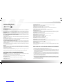
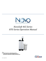
COMMANDOMATIC WATER SOFTENER/ PURIFIER SYSTEMS
Each unit comprises of:
Pressure vessel containing a bed of cation or cation/ anion exchange resin, which does the softening/ purifying.
Brine tank to store and provides the salt, to make up the salt brine solution needed for regeneration.
A 10 valve, which directs the ow of water through the cycle of regeneration and service.
How does a Commandomatic water Softener/ Purier work?
The water softening/ purifying resin is held within the pressure vessel. The resin sits on top of a gravel bed and a
centre tube passes through the resin to provide up or down ow when required. Normal ow is down through the
resin bed and back up the centre tube. During salt regeneration, the ow is reversed.
Salt is stored in the brine tank. A oat allows a set amount of water into the brine tank. This water dissolves
enough salt to regenerate the water softener/ purier. The brine solution is then transferred into the resin cylinder.
This is achieved by means of an injection system, which draws the brine solution up, and passes it through the
resin bed and out to the drain.
. . . . . . .
. . . . . . .
. . . . . . .
. . . . . . .
. . . . . .
. . . . . . . . . . . . . . . . .
. . . . . . . . . . . . . . . .
. . . . . . . . . . . . . . . . .
. . . . . . . . . . . . . . . .
To Drain Mains Water
Unsoftered
Water to
House
RINSE
. . . . . . . . . . . . . . . . .
. . . . . . . . . . . . . . . .
. . . . . . . . . . . . . . . . .
. . . . . . . . . . . . . . . .
. . . . . . .
. . . . . . .
. . . . . . .
. . . . . .
. . . . . .
To Drain
Salt
Brine
Solution
Mains Water
Unsoftered
Water to
House
BACKWASH BRINE
. . . . . . . . . . . . . . . . .
. . . . . . . . . . . . . . . .
. . . . . . . . . . . . . . . . .
. . . . . . . . . . . . . . . .
. . . . . . .
. . . . . . .
. . . . . . .
. . . . . .
. . . . .
Mains Water
Soft Water
to House
NORMAL FLOW
Salt
Brine
Solution

Waterco Commandomatic
LID
INLET
OUTLET
DRAIN
SOLENIOD
VALVE
PRESSURE
VESSEL
BRINE TANK
STRAINER
TRANSFORMER
CONTROLLER
PRESSURE
RELIEF
A10 VALVE
INSTALLATION INSTRUCTIONS
These instructions apply to both Filters and Softeners.
If a Softener, Softener/
Purier or Carbon unit is to be
installed in an area where there
is sediment,it is advisable
to install a sediment lter to
keep the media bed clean
and prevent the jamming of
the solenoid valves on the
automatic units.
Check the size of the house.
Larger houses generally have
2 or 3 showers/ bathrooms,
automatic dishwashers and
washing machines and have
20mm (3/ 4”) or 25mm (1”)
pipe supply. This is to ensure
adequate ow rate if two or
more units are in operation at
any one time. Unit selection
must therefore be based on
ow rates and capacity, to
prevent pressure/ ow loss.
CHECKLIST
The unit should be installed:
a) ON a rm level, i.e. a cement path or pre-cast slab.
b) Within three metres of a gully trap or sink. If the distance is greater, the drain pipe size must
be increased to 20mm.
c) Do not supply treated water to the garden taps.
Pressure requirements – Maximum 825 kPa (120 psi) Minimum 275 kPa (40 psi).
a) If the available pressure is lower than 275 kPa the water softener’s A10 valve will not be able
to function properly.
b) If the pressure is above 825 kPa (120psi), t a pressure limiting valve. A pressure limiting valve
is also recommended if your area is subject to high pressure uctuations and/ or it is a
requirement of your local Water Authority.
The transformers used on automatic units are not suitable for external installation and should be installed inside or pro-
tected by a weatherproof shroud.
NOTE : In multiple installations, lters are always installed upstream of softeners.
!
CAUTION
CONNECTIONS
Each unit has 3 connections; drain inlet and outlet. These will be 15mm or 25mm, depending on the model
selected.
1) Fit an isolation valve to the inlet supply. This can be in the form of an approved gate valve or ball valve.
2) Connect inlet (top) & outlet (bottom).
3) Connect drain line to either the timer (semi-auto) or to the solenoid (fully auto), using 15mm exible hose and
run to drain. Leave a 75mm gap between end of drain line and the drain for observation of ow.
4) If the drain is more than 3 metres from the unit, the drain hose size must be increased to 20mm.
5) Connect overow hose (supplied). Do not interconnect overow line with drain line, run as a separate and also
leave a 25mm gap. NB Filters do not have an overow.
6) All softeners have a cabinet overow, which should be connected to the drain with a exible hose.
7) If the unit is a softener, load one or two 25kg bags of Commandomatic Water Softener Salt into the Brine Tank
to ensure the tanks is about two thirds full.
INITIAL OPERATION
If a Commandomatic Automatic Controller is tted to the unit, please program the Controller before initial
operation of the unit, refer to “Programming the Controller ” .
a) For Filters : Turn on the inlet valve. Start the Filter in the backwash cycle. When the vessel has
filled, there will be a continuous water flow to the drain. Allow the unit to backwash
for 15 minutes, the unit will then return to normal operation.
b) For Softeners : Turn on the inlet valve. Start the Softener in the regeneration cycle. When the vessel
has lled, there will be a continuous water ow to the drain. As soon as this happens,
regeneration may be terminated, which will return your softener to normal operation.
Then salt may be loaded. Your softener has been factory regenerated and is ready for
immediate use.
I pg 05

Waterco Commandomatic
WHEN AND HOW TO REGENERATE OR BACKWASH
Please note that regeneration refers to softeners/ puriers and backwashing refers to lters.
SEMI-AUTOMATIC REGENERATION
Normal regeneration time is 60 minutes; However, it may need to be extended up to 90
minutes in areas where the water pressure is low.
For Semi-Automatic Regeneration simply turn the dial on the Commandomatic timer, the
unit will automatically return to normal operation after the regeneration is completed.
Salt
Be sure to use Commandomatic salt (approximately 1/4” pellets), as it is specially
selected large granule salt, graded for maximum efciency and packed in 25kg moisture
proof bags. This will prevent “ bridging ”, as would occur if ne salt were used. Your brine
tank holds 50kg – or 2 bags of salt. When salt level drops to approx. half the depth of the
brine tank, add another bag of salt.
SOFTENER AND SOFTENER/ PURIFIER REGENERATION
It is advisable to regenerate your water softener/ purier on a regular basis. The frequency of regeneration will
vary according to the amount of water being used and its hardness. Find out the approximate hardness of the
water supply in question, this can usually be obtained from the local Water Authority.
A calculation can be made to estimate usage, to enable a regeneration schedule to be prepared. Each person will
use approximately 125 litres of water per day. An automatic washing machine and/or dishwasher each counts
as an additional user.
Therefore, a family of ve with a dishwasher and washing machine will use approximately 7 X 125 litres of water
per day – total 875 litres. 875 litres per day X 7 days = 6,125 litres per week.
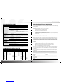
The following chart details the capacity of each unit. To nd the frequency of regeneration, divide the capacity of
the unit by the calculated daily usage rate.
From the chart above, it can be seen if a W7 is used, the unit requires regeneration every 8 days if the water
hardness is 140 mg/ L. (i.e. 6964 ÷ 875 litres/ day = 8 days) If the larger S14 softener is used, the unit only requires
regeneration every 16 days. (I.e. 13928 ÷ 875 litres/ day = 16 days).
The chosen unit should offer the most convenient regeneration period to suit the user whether it be Semi-
Automatic or Fully Automatic.
HARDNESS CAPACITY W7 CAPACITY WPS4 CAPACITY S14 CAPACITY PS9
Mg/ L Unit (Litres) (Litres) (Litres) (Litres)
10
25
50
75
100
125
140
150
175
200
225
250
275
300
325
350
375
400
425
450
475
500
97500
39000
19500
13000
9750
7800
6964
6500
5571
4875
4333
3900
3545
3250
3000
2786
2600
2438
2294
2167
2052
1950
65000
26000
13000
8667
6500
5200
4642
4334
3714
3250
2889
2600
2364
2167
2000
1857
1733
1623
1529
1444
1368
1300
195000
78000
39000
26000
19500
15600
13928
13000
11142
9750
8666
7800
7090
6500
6000
5572
5200
4876
4588
4334
4101
3900
130000
52000
26000
17334
13000
10400
9284
8668
7428
6500
5778
5200
4728
4334
4000
3714
3466
3246
3058
2888
2736
2600
UNIT CAPACITY CHART FOR COMMANDOMATIC MODELS
Salt Usage
COMMANDOMATIC UNIT SALT USAGE PER REGENERATION (kg)
W7(A)
S14(A)
WPS4(A)
WPS9(A)
4.5
7
4.5
7
FILTER BACKWASH
Back wash time is approximately 15 – 20 minutes. Frequency is dependent on the amount of sediment in the
water. As a rough guide:
Bad water, backwash should be carried out every second day
Average water, backwash should be carried out once a week.
Semi-Automatic Backwash
To backwash sediment and carbon lters simply turn the timer the dial on the Commandomatic timer to the 15
minute mark, the unit will automatically return to normal operation after the backwash is completed.
Fully-Automatic Backwash – refer to Commandomatic Automatic Controller (Page: 9).
Check the wastewater at drains to ensure that backwash is complete i.e. the backwash water is clean
after 15 minutes.
Backwash water from lters can be run into gardens. If drain line is longer than three metres use a
20mm diametre hose.
Mixed media and carbon lters must be regularly backwashed and rinsed to help prevent
contamination from bacteria growths. Maintenance is customer’s responsibility.
NOTE:
All units have automatic by-pass, which enables water to be used inside the house during regeneration.
If the pressure is low the unit may take longer than the recommended backwash time.
The salt used for regeneration passes through the resin bed and out to the drain. It is not strong enough to harm a
septic tank and will not affect the bacterial action, which takes place.
These units are not designed for the removal of micro organisms and may result in the accumulation of micro
organisms. It is therefore important that lters are used on microbiologically safe water and that ushing
and maintenance protocols are strictly adhered to.
I pg 07

Waterco Commandomatic
Volumatic (with ow meter)
The unit keeps track of how much water has been processed since the last regeneration and automatically
regenerates once the remaining capacity is less than the daily reserve capacity. However if the calendar override
is set and if the number of days is equal or greater than the calendar setting, regeneration will be initiated at the
regeneration time.
Calendar Timer (no ow meter)
The units keep track of the length of time since the last regeneration/ backwash and automatically regenerates /
backwash once the programmed calendar setting has been reached.
COMMANDOMATIC AUTOMATIC CONTROLLER
The Commandomatic Automatic Controller tted to your Commandomatic unit is a programmable
microprocessor. There is the option of either the Volumatic or the Calendar Timer.
PROGRAMMING THE CONTROLLER
Plug in the supplied power pack and connect the power pack to the Commandomatic Controller. The capacity
display will be shown as below, with the timer initiated.
UP, DOWN, SELECT and MANUAL keys.
Operation of the menus and settings are accessed with the UP/ DOWN and SELECT keys.
A) UP/ DOWN - These buttons are used to move through the numerous displays in either service mode
or running mode and to increase or decrease values. When holding down one of the buttons, a slow
stepping action begins which after ve seconds switches to fast stepping.
B) SELECT - This button is used to allow the setting of shown values in a display during service mode.
The rst press changes to an editing mode, a value will ash on the display, and this value can be
modied using the UP/ DOWN buttons. The second press advances to the next value on the display.
When the last value on the display has been modied, pressing the SELECT button will exit editing mode
and advance automatically to the next display. The value in the next display can be modied simply be
repeating the process by pressing the SELECT again.
C) MANUAL - This button is used for manual regeneration/ backwashing and for the initial lling of
the unit.
Calendar Timer - Softener / Purier
1. Press SELECT to enter the Access Code display.
2. Enter the Access Code 1357 via the UP button. After each input press SELECT and the number will convert to an
Asterix (*), once all the numbers are entered, press SELECT to exit and the Display will revert to the default display.
3. Scroll to “Set Time”, press SELECT and set the current time.
4. Scroll to “Calendar Override” press SELECT and set the number of days in between regenerations.
This is determined by the amount of water being used and the level of hardness; please refer to the “Softener
and Softener/ Purier Regeneration”.
5. Scroll to “Regeneration Time”, the default setting is at 2:00am, if you wish to change this setting, press
Select and input the new regeneration time.
6. Scroll to “Regeneration Period”, press SELECT and input the appropriate regeneration period
according the table below:
7. Scroll to “Set Salt Warning”, press Select and set the salt warning according to the table below:
Volumatic Controller - Softener/ Purier
1. Press SELECT to enter the Access Code display.
2. Enter the Access Code 8624 via the UP button. After each input press SELECT and the number will convert to an
Asterix (*), once all the numbers are entered, press SELECT to exit and the Display will revert to the default display.
3. Scroll to “Set Time”, press SELECT and set the current time.
4. Scroll to “Calendar Override” you can either leave the setting at its default setting of 99 days or press SELECT
and set the maximum number of days in between regenerations. The Volumatic will regenerate based on volume,
but if the number of days is equal or greater than the calendar setting, a regeneration will be initiated.
5. Scroll to “Regeneration Time”, the default setting is at 2:00am, if you wish to change this setting,
press Select and input the new regeneration time.
6. Scroll to “Regeneration Period”, press SELECT and input the appropriate regeneration period
according the table below:
7. Scroll to “Set Capacity”, press SELECT and input the appropriate capacity according to the table below:
8. Scroll to “Set Hardness”, press SELECT and input the hardness of your water in milligrams per litre.
The hardness of the water supply can be obtained from your local Water Authority.
9. Scroll to “Set Salt Warning”, press SELECT and set the salt warning according to the table below:
After programming and installation.
Once the unit is installed activate battery-backed memory, by removing the tab shown in the photo.
Unit Model No. W7 / WPS4 PS9 / S14
Regeneration Time 60 mins 80 mins
Unit Model No. W7 / WPS4 PS9 / S14
Salt Warning 10 Regenerations 7 Regenerations
Unit Model No. W7 / WPS4 PS9 / S14
Regeneration Time 60 mins 80 mins
Unit Model No. W7 WPS4 S14 PS9
Capacity 975 000mg 650 000mg 1950 000mg 1300 000mg
Unit Model No. W7 / WPS4 PS9 / S14
Salt Warning 10 Regenerations 7 Regenerations
I pg 09

Waterco Commandomatic
CONTROLLER DISPLAYS
Volumatic Display
The capacity bar graph display has been implemented to indicate the remaining capacity as a percentage of the
bar, excluding the reserve capacity.
When the remaining capacity reaches the reserve capacity, the capacity bar graph will be blank before indicating
the reserve capacity. As the reserve capacity is depleted, the display will alternate between the capacity bar
graph and the text “RESERVE”. Once the reserve water is being used, the unit will go into regeneration at the set
regeneration time.
The reserve is automatically calculated by the unit to cope with demand. Its value species how much more water
the unit can soften before regeneration. The reserve value shown increases until it reaches the reserve limit, at
which point the word “RESERVE” will be replaced with “OVERRUN”.
Calendar Timer Display
As the Calendar Timer is based purely on a set time and date, the capacity bar graph displaying capacity remains
unchanged.
Regeneration/ Backwash Display
During regeneration the capacity bar graph will indicate the percentage of time to completion and will alternate
the display between the capacity bar graph and the text “REGENERATING”.
Low Salt Warning (Softeners & Softeners / Puriers only)
The “Low Salt” warning keeps track of the number of regeneration’s that have been performed before indicating
“LOW SALT” on the main display. When a low salt condition occurs the main display will toggle between the
capacity bar graph and the text “LOW SALT”. The salt should be replaced and then press the SELECT key to
reset the low salt warning.
Sand and carbon lters do not require the “Low Salt Warning”, therefore the “Low Salt Warning”, must be set to
“0” to de-activate the low salt indicator.
Power Loss
If power is lost to the unit for over seven days, the user settings and time settings are lost. A “POWER LOSS”
message will be shown on power resuming. The unit has battery-backed memory for all service and user
parameters. In the event of a power failure, the time clock in the unit will keep the correct time and all settings
will be retained for up to seven days.
If at the time of the power failure the unit had been regenerating the resin bed, the unit will begin that cycle from
the start as soon as power is resumed to the unit.
NOTE: Even if there is one minute left in the cycle it will always start from the beginning on the resuming power.
Pull tab to activate
memory battery
REPLACING THE A10 VALVE AND CLEANING THE FILTER BED
1. Turn off the mains water inlet tap and open the drain tap to relieve the pressure.
2. Remove the two stainless steel clips and disconnect the drain line.
3. Turn the complete valve anti-clockwise for several turns until it can be lifted clear of the cylinder. The centre tube
assembly may come away with the valve. If so, place a hose back into the bed so that whilst water from the hose
is swirling the bed material, the centre tube can be pushed back down through the bed until the top of the tube
is level or below the top of the cylinder.
4. Re-assemble the unit, using a new “ o ” ring seal with the new valve. Place grease on the valve thread and start
the valve lightly, being careful not to cross the threads. Tighten the valve by hand –DO NOT USE EXCESSIVE FORCE.
5. If a washout is required – lay the unit on a table or support and hose the contents out of the cylinder into a large
bucket or container. Separate the gravel if possible.
6. Wash the sand/ carbon until it is free of mud and dirt.
7. Place the unit in an upright position and replace the centre tube and screen assembly ensuring there is no gravel
left in the bottom of the cylinder. Place a temporary plug in the top of the centre tube then using a large
funnel;replace the cleaned gravel followed by the sand/ carbon. Remove the temporary plug. Rell with water
and re-assemble with the valve as above.
8. Re-connect unit and backwash until clean.
ADDITIONAL DISPLAYS AND SERVICE MENUS
Access Code
Pressing the SELECT key accesses this menu, while the Main display is showing. A 4-digit access code is entered
to set the access level required for setting various values indicated above.
NOTE: The display will always return to the main display if there is no keyboard activity for 15 seconds.
Remaining Cap (display only)
This displays the true remaining capacity including the reserve capacity in milligrams.
Current Usage (display only)
This displays the current daily use since the previous day’s regeneration/ backwash time in milligrams.
Previous Usage (display only)
This displays the previous day’s usage up to the last regeneration/ backwash time in milligrams.
Average Usage (can be set with access code 8624)
This displays the current average in milligrams, which can be adjusted.
Set Time (can be set without access code)
Allows adjustment of the clock time. Note that adjustment of the minutes will reset the seconds to zero.
Calendar Override (can be set with access code 1357)
Displays and sets the calendar override function. A value of zero disables this function.
Remaining Regens (display only)
This displays the number of regeneration cycles left before indicating the warning for “LOW SALT”. Once the low
salt warning appears, further regeneration is halted until the salt is replenished and the low salt warning is reset.
Set Regen Time (can be set without access code)
Displays and sets the time when automatic regeneration/ backwash should normally occur.
Set Reg. Period (can be set without access code)
Displays and sets the duration of the regeneration/ backwash cycle in minutes.
Set Capacity (can be set with access code 8624)
Displays and sets the capacity of unit. 50 000mg (default)
Set Hardness (can be set with access code 1357)
Displays and sets the hardness of the water in milligrams per litre.
Set Salt Warning (can be set with access code 1357)
Displays and sets the number of regeneration cycles, which can occur before requiring a rell of salt in the brine
tank. Set salt warning to “0” for Sediment and Carbon Filters to de-activate the low salt warning.
Set Pulses/ Litre (can be set with access code 8624)
Displays and sets the calibration for counting ow pulses from the ow sensor.
Flow in 1 min (display only)
Displays the accumulated number of litres owing in a one minute period. Pressing the SELECT key can restart
the one minute period.
I pg 11

Waterco Commandomatic
TROUBLESHOOTING GUIDE SERVICE AND MAINTENANCE INFORMATION
1. The salt storage compartment of your softener should be maintained at a level between one third and two thirds
full. Use Commandomatic Salt as it is a Large Granule salt, graded for best efciency and it is packed in 25kg
moisture proof bags.
2. During regeneration, untreated water is by-passed to service, so water is available to the house.
3. Waste water from regeneration may be run into a septic tank system.
4. Solenoid Valve
a) Power and water must be turned off before removing.
b) When ordering spare parts specify 240 Volt or 24 Volt.
5. Manual Timer
a) To clean manual timers, turn off the water supply to the unit.
b) If necessary, clean out the valve: Unscrew the cover, remove the lock cone, spring and membrane and
rinse thoroughly under owing water. Replace the parts in the reverse sequence, taking care that they
are tted correctly.
PROBLEM PROBABLE CAUSE REMEDY
Unit not softening
No salt in brine tank Rell with Commandomatic salt and allow 2 hours for the salt to
dissolve and then regenerate manually.
Electrical failure a) Check the power is turned on.
b) Check for blown fuse ( household power ).
c) Lead may have been removed from power point.
d) Solenoid coil may be faulty, check and replace, if necessary. †
Salt bridging in brine tank above wNot
drawing brineevel
Take probe ( i.e. broom handle or similar ) and break salt bridge
carefully.
Not drawing brine a) Check brine valve and clean, if necessary. †
b) Pressure is low – minimum recommended pressure is 275kPa.
c) Injector is clogged. Remove and clean. †
Water Hardness has increased Check water hardness
Dripping from
Pressure Relief
High Pressure Install a 600kPa pressure limiting valve. Relief valve may need
replacement. †
Dirty water
Dirt build up Unit requires a pre-lter. In poor quality water areas there will be
some dirt-build up in the resin bed even after a lter is installed.
Salt taste
Low water pressure Increase regeneration time.
Excess brine Check brine level in tank. Clean Brine valve.
Blocked injector Remove and clean. †
Unit Overowing
Dirt in brine valve assembly Remove check and clean brine valve. †
Unit continues
running to drain
after regeneration
Dirt in solenoid or timer Remove diaphragm and clean. †
Not drawing brine
Blockage in brine valve Remove and clean. †
Seals in main valve need replacement Replace seals. †
Blocked injector Remove and clean. †
† Should be performed by a qualied service technician to avoid personal injury or property damage.
WARNING : ENSURE WATER AND POWER IS TURNED OFF PRIOR TO SERVICING.
* If loading salt into brine tank, water displacement will increase water level height – this is normal
CODE 3532005 3532006 3534010 3535444 3530015 3530012 3530013 3533009
Product Soft/ Resin Purify/ Resin Anthracite 1/2 x 1/4 gravl 6/8 Gravel 8/16 Sand 30/60 Sand Act-Carbon
W7
W7A
S14
S14A
WPS4
WPS4A
PS9
PS9A
MB6
MB6A
FS40
FS40A
CF6
CF6A
CU40
CU40A
17 Litres
17 Litres
34 Litres
34 Litres
11 Litres
11 Litres
22 Litres
22 Litres
6 Litres
6 Litres
12 Litres
12 Litres
4 Litres
4 Litres
6 Litres
6 Litres
5 Litres
5 Litres
4 Litres or 4 Litres
4 Litres or 4 Litres
6 Litres or 6 Litres
6 Litres or 6 Litres
4 Litres or 4 Litres
4 Litres or 4 Litres
6 Litres or 6 Litres
6 Litres or 6 Litres
4 Litres
4 Litres
3 Litres
3 Litres
4 Litres
4 Litres
6 Litres
6 Litres
4 Litres
4 Litres
8 Litres
8 Litres
14 Litres
14 Litres
28 Litres
28 Litres
Please Note : 8/16 Sand may be used as a substitute for 6/8 Gravel, if 6/8 Gravel is not available.
COMMANDOMATIC MEDIA CAPACITIES
COMMANDOMATIC WARRANTY
Waterco Limited ( hereinafter called “ The Company ” ) guarantees this Commandomatic appliance for one
year subject to “ Conditions ” set out hereunder, to be free from defects in material and workmanship under
normal use and service. The obligation of the Company shall be limited to replacing or repairing ( at the option
of the Company ) any part of the said appliance which proves thus defective within one year from the date
of the original purchase and which the Company’s examination shall disclose to its satisfaction to be thus
defective.
Conditions
This warranty does not cover faults arising from the following causes:
a) Appliances not installed in accordance with the Company’s installation instructions.
b) Accident, alteration, negligence, abuse, misuse, ood, re and Acts of God.
c) If repairs are conducted by any person or persons not approved by the Company.
d) Operation at water pressure outside the range shown on the appliance or operation
of the unit with excessive water hammer caused by other appliances.
The Company does not accept responsibility for any costs or charges, involved in transporting the appliance
to or from the Company’s premises, or those of its accredited agent, for the purpose of repair, replacement
or adjustment.
This warranty is the sole warranty given by the Company, and the Company neither assumes nor authorizes
any person to assume for it, any other obligation or liability in connection with this Commandomatic appliance,
or part thereof.
IMPORTANT – This warranty must be completed and RETAINED by the owner. Keep this certicate together with your purchase
docket in a safe place – you will have to produce them should you require service under the terms of this warranty.
Tested by _____________________________________ Purchase Date ____________________________
Model No._____________________________________ Serial No. ________________________________
Owner’s Name__________________________________________________________________________
Address _______________________________________________________________________________
Installer’s Name ________________________________________________________________________
Builder, Plumber ________________________________________________________________________
Address _______________________________________________________________________________
I pg 13
-
 1
1
-
 2
2
-
 3
3
-
 4
4
-
 5
5
-
 6
6
-
 7
7
-
 8
8


Waterco CU40 Series Owner's manual
- Type
- Owner's manual
- This manual is also suitable for
Ask a question and I''ll find the answer in the document
Finding information in a document is now easier with AI
Related papers
Other documents
-
DAYLIFF SF User manual
-
 IBC Water 500 Series Installation & Operating Instructions Manual
-
KENT 111013 User manual
-
Aqua Water Softner System Equo Soft Mini User manual
-
 AQUATECH 565 Series Operating instructions
-
US Water LASER User manual
-
Pentair FLECK 5812 XTR Installer Manual
-
Hydrotech 80150307 565 HT Softener Owner's manual
-
Hellenbrand promate 6.0 Owner's manual
-
 NOVO NVO465-100C Operating instructions


