Page is loading ...

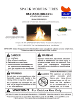
DANGER - IF YOU SMELL GAS
1. Shut o gas to the appliance.
2. Extinguish any open ame.
3. If odor continues, keep away from the appliance and immediately call your gas
supplier or re department.
WARNING
Do not store or use gasoline or other ammable vapors and liquids in the vicinity of this
or any other appliance. An LP-cyllinder not connected for use shall not be stored in the
vicinity of this or any other appliance.
CARBON MONOXIDE HAZARD
This appliance can produce carbon monoxide which has no odor.
Using it in an enclosed space can kill you.
Never use this appliance in an enclosed space such as a camper, tent, car
or home.
WARNING:
Improper installation, adjustment, alteration, service or maintenance can cause injury
or property damage. Read the installation, operating and maintenance instructions
thoroughly before installing or servicing this equipment.
WARNING: FOR OUTDOOR USE ONLY!
DANGER
ROBATA 72 & 54 CONCRETE
Meets the essential requirements as described in the European Directive 2009/142/EC
INSTALLER: Leave this manual with the appliance. CONSUMER: Retain this manual for future reference
Match-lit
Installation + Owner's Manual

2ROBATA 72/54 CONCRETE FIRE CE Match-lit | Installation & Owner’s Manual
SAFETY INFORMATION
WARNINGS:
IMPORTANT: This appliance should
be inspected before use and at least
once annually by a qualied service
person.
More frequent cleaning may be
required as necessary. It is imperative
that the control compartment,
burners and circulating air
passageways of the appliance be
kept clean.
DANGER: Carbon monoxide
poisoning can lead to death!
CARBON MONOXIDE POISONING:
Early signs of carbon monoxide
poisoning resemble the u, with
symptoms including headache, dizziness,
or nausea. If you experience these
signs, the Fire Pit may not be working
properly. Get fresh air at once! Have the
Fire Pit serviced. Some people are more
aected by carbon monoxide than others,
including pregnant women, people with
heart or lung disease or anemia, those
under the inuence of alcohol, and those
at high altitudes.
NATURAL GAS AND PROPANE:
To assist in detecting leaks, an odorant
has been added to natural gas and
propane. However, this odorant can fade,
and gas may be present even though no
odor exists. Make certain you read and
understand all warnings. Keep this manual
for reference. It is your guide to safe and
proper operation of this appliance.
WARNING: Any modication to this appliance or its
controls can be dangerous.
Read instructions before installation and use.
1. This appliance, as supplied, is only for use with the
type of gas indicated on the rating plate.
2. This appliance is intended to be connected to a xed
piping system. The installation must conform to local
and/or national codes.
3. Never leave the re unattended.
4. Keep the appliance area clear and free from
combustible materials, gasoline and other ammable
vapors and liquids
5. Use only the type of gas that is specied by the
manufacturer.
6. Do not burn solid fuel in this appliance. Do not use
this appliance to cook food or to burn paper or other
objects.
7. Children and adults should be alerted to the hazards
of high surface temperatures and should stay away
to avoid burns or clothing ignition.
8. Clothing or other ammable materials should not be
hung from the appliance, or placed on or near the
appliance.
9. Young children should be carefully supervised when
they are in the area of the appliance.
10. Do not use the appliance if any part has been under
water. Immediately call a qualied service technician
to inspect the appliance and to replace any part of
the control system and any gas control which has
been under water.
11. In case of violent wind particular attention must be
taken against the tilting of the appliance.
12. Inspect the appliance before each use.
13. Do not move the appliance when in operation. Shut
o gas at source before moving the appliance
14. Turn the appliance o and let cool before servicing,
installing, repairing or covering. Any guard or other
protective device removed for servicing the appliance
must be replaced prior to operating the appliance.
Only a qualied service person should install, service,
or repair the appliance.
FOR OUTDOOR USE OR IN AMPLY VENTILATED AREAS
• An amply ventilated area must have a minimum of
25% of the surface area open.
• The surface area is the sum of the walls surface

3ROBATA 72/54 CONCRETE FIRE CE Match-lit | Installation & Owner’s Manual
BASIC ASSEMBLY
METAL COVER
(OPTIONAL)
PILOT ASSEMBLY
BURNER ASSEMBLY
FLEX CONNECTOR
PIPE ADAPTER
TOP
TOPPING TRAY
GAS SUPPLY
BODY
CONTROL KEY
ROBATA 72ROBATA 54
1. UNPACK: Account for all parts (p. 15-16)
2. FRAGILE: Handle with care
3. LEVEL: Place on a solid, level surface
4. AIR VENTS: Do not block ventilation gaps (p. 4-5)
5. GAS / PROPANE: Supply line is routed through the base of
the unit and must be installed by licensed trades.
6. MEDIA TOPPINGS: Review correct placement (p. 7-8)


6ROBATA 72/54 CONCRETE FIRE CE Match-lit | Installation & Owner’s Manual
SPECIFICATIONS & CLEARANCES
1829
mm
203
mm
ROBATA 54
NATURAL GAS
ROBATA 54
PROPANE
ROBATA 72
NATURAL GAS
ROBATA 72
PROPANE
Burner Model # LIN-E-36 LIN-E-36P LIN-E-48 LIN-E-48P
Heat Input G20, 20 mbar
20 kW
G31, 37 mbar
18 kW, 1210 gr/h
G20, 20 mbar
27 kW
G31, 37 mbar
25 kW, 1758 gr/h
Burner Pressure 8.7 mbar 25 mbar 8.7 mbar 25 mbar
Orice Size 26 43 18 37
Burner Ports 35 35 47 47
Port Size 1/8" (~3 mm) 1/8" (~3 mm) 1/8" (~3 mm) 1/8" (~3 mm)
MINIMUM CLEARANCES TO COMBUSTIBLES
1829
mm
203
mm

7ROBATA 72/54 CONCRETE FIRE CE Match-lit | Installation & Owner’s Manual
TO ASSEMBLE THE FIRE PIT
1. Assemble re pit housing per diagram on page 3.
2. Connect the Burner Assembly to the gas supply using the
supplied ex connector, following the instructions on p 9.
3. Carefully leak test all connections following the procedure
on p 9. Check the air shutter on venturi. For NG it is sealed.
For LP it is fully open (see part 2a, pg 14)
4. Fill the burner trough evenly with burner media (crushed
tempered glass for natural gas; volcanic rock for propane).
Do not obstruct the pilot ignition port with burner media! Do
not use media not supplied by Paloform!
5. Place the burner assembly on a stable surface. Ensure
burner is level.
6. Follow the Initial Lighting Instructions on page 10. Make
sure that the ame is even along the burner length and
appliance is fully operational and safe for use. Turn OFF the
appliance and let it cool before proceeding to the next step.
7. Carefully lift the burner and place it in the Robata body.
(See page 3)
8. Place and evenly distribute decorative topping media (lava
rock or tempered glass pebble) on top of burner media.
(See page 8). Decorative media should be brought level
with the top of the pilot cover. An uneven or excessively
thick layer of topping can result in an uneven ame.
Do not obstruct PILOT IGNITION PORT!
9. Correct ame appearance:
WARNING:
Failure to position parts in accordance
with these diagrams and instructions
and/or failure to use parts specically
approved for use with this appliance may
result in property damage or personal
injury.
Do not remove the data plates attached
to the Outdoor Fire Pit Burner. These
plates contain important information.
NOTICE:
Installation and repair should be done by
a qualied service person. The appliance
should be inspected before use and at
least once annually by a qualied service
person. More frequent cleaning may be
required as necessary. It is imperative
that control compartment, burner ports
and circulating air passageways of the
appliance be kept clean.
CAUTION:
New Lava Rock may pop or crackle when
rst heated. This should subside after 30
minutes to one hour or more of operation.
Maintain safe distance during this time.
ASSEMBLY
DECORATIVE
TOPPING
BURNER
MEDIA
IGNITION
PORT


9ROBATA 72/54 CONCRETE FIRE CE Match-lit | Installation & Owner’s Manual
CONNECTING TO GAS SUPPLY
WARNING:
A qualied service person must connect
the appliance to the gas supply. Follow all
local codes.
CAUTION:
Use only new black iron or steel pipe.
Internally tinned copper tubing may be
used in certain areas. Use pipe of 1/2”
diameter or greater to allow proper gas
volume to Outdoor Fire Pit Burner. If pipe
is too small, undue loss of pressure will
occur.
INSTALLATION ITEMS NEEDED:
Before installing the Outdoor
Fire Pit, make sure you have all items
listed bellow:
• piping (check local codes)
• sealant
• manual shuto valve
• adjustable (crescent) wrench or pliers
• sediment trap
• tee joints
• pipe wrench
INSTALLATION REQUIREMENTS
This appliance must be installed and serviced by trained
gas installation and service technician only. All pipework
must be supported and installed in accordance with local
and/or national regulations.
• The gas supply to the appliance must terminate
with an isolation cock and a exible connector.
This will allow the appliance to be disconnected for
maintenance or repair. The appliance is supplied with
a 1/2” BSP male pipe tting.
• Check that the main gas supply line is of proper
diameter to supply the required fuel pressures. Pipes
of a smaller size than the heater inlet gas connection
must not be used.
• If utilizing used pipe, verify that its condition is clean
and comparable to a new pipe. Test all gas supply
lines in accordance with local codes.
• Test and conrm that inlet pressures are correct.
Refer to the heater data plate and packaging to verify
fuel type.
• Install a sediment trap/drip leg for condensation
which may occur at any point of the gas supply line.
This will decrease the possibly of loose scale or dirt
in the supply line entering the appliance’s control
system and causing a malfunction.
CHECKING GAS CONNECTION
WARNING: Test all gas piping and connections
for leaks after installing or servicing. Correct all leaks
immediately.
WARNING: Never use an open ame to check for
a leak. Apply a mixture of liquid soap and water to all
joints. Bubbles forming on joints while the gas is running
indicate a leak. Correct all leaks at immediately.
Test Pressures in Excess Of 37 mbar
This appliance and its individual shuto valve must be
disconnected from the gas supply piping system during
any pressure testing of that system at test pressures in
excess of 37 mbar.
Test Pressures Equal To or Less Than 37 mBar
This appliance must be isolated from the gas supply
piping system by closing its individual manual shuto
valve during any pressure testing of the gas supply piping
system at test pressures equal to or less than 37 mbar.

10ROBATA 72/54 CONCRETE FIRE CE Match-lit | Installation & Owner’s Manual
LIGHTING YOUR FIRE PIT
WARNINGS:
Failure to follow these instructions exactly may result in re or
explosion causing property damage, personal injury or loss
of life.
Before operating the appliance, check all around the appliance
area and on the surrounding oor for the smell of gas - some
gas is heavier than air and may settle on the oor in the event
of a leak. IF YOU SMELL GAS, follow the safety instructions
on page 1 of this manual.
This appliance is equipped with an ignition device that
automatically lights the pilot. Do not try to light the pilot
manually.
The main gas valve in this appliance is not serviceable and
does not have any control knobs or switches to operate. Do
not remove the heat shields covering the valve and electronic
devices. Do not try to repair or modify the valve, as doing
so may result in a re or explosion. Call a qualied service
technician if you have any safety concerns.
Do not use this appliance if any part of it has been under
water. Immediately call a qualied service technician to
inspect the appliance and to replace any part of the control
system and any gas control that has been under water.
Improper installation, adjustment, alteration, service or
maintenance can result in injury or property damage. For
assistance or additional information, consult a qualied
installer, service agency or the gas supplier.
Do not store or use gasoline or other ammable vapors or
liquids in the vicinity of this appliance.
INITIAL LIGHTING INSTRUCTIONS
Before placing burner assembly into a housing:
1. Purge air from the supply line.
2. Test for leaks in each of the following locations:
• The gas supply line connection to the main valve;
• The Burner connections and pilot;
• All joints on the valve and control body;
• All eld made joints and gas shuto valves;
• All factory made joints and connections.
3. You may check for gas leaks using one of the following methods only:
• Soap and water solution. WARNING: If using a soap and water solution to test
for leaks, DO NOT spray the solution onto electronic parts;
• An approved leak testing spray;
• An electronic snier. NOTE: Remove any excess pipe compound from
connections if using this method, as the compound can set o electronic sniers.
DANGER: NEVER USE AN OPEN FLAME TO CHECK FOR GAS LEAKS.

11ROBATA 72/54 CONCRETE FIRE CE Match-lit | Installation & Owner’s Manual
LIGHTING YOUR FIRE PIT
STOP!
Review the safety information on
pages 1, 2 and 10 of this manual.
150°
90°
30°
OFF
PILOT
HIGH
LOW
OPERATING INSTRUCTIONS
Use only your hand to push in or turn the gas control knob. Never use tools. If the knob will not
push in or turn by hand, don’t try to repair it, call a qualied service technician. Force or attempted
repair may result in a re or explosion.
1. Turn the gas control knob to the OFF position (it will be necessary to depress the knob slightly
at the PILOT position). Allow ve minutes for any gas in the vicinity to dissipate. (LP gas, which
is heavier than air, may require forced ventilation).
2. Push knob slightly and turn the gas control knob to the PILOT position.
3. Push down on the gas control knob and light the pilot immediately by applying a ame to the
lighting port. Hold the knob down for one full minute after lighting the pilot.
4. When the gas control knob is released, the pilot ame should continue to burn (if the pilot
goes out, repeat the above steps).
5. Rotate the gas control knob without pushing, from PILOT to HIGH position (90°
counterclockwise position) to supply full ow to main burner.
NOTE: Not turning the gas control knob to the full ON position will reduce the ow and could result
in poor ignition of main burner.
6. To extinguish main burner, rotate the gas control knob clockwise to the PILOT position.
7. To extinguish pilot, depress control knob slightly and turn to the OFF position (fully clockwise).

12ROBATA 72/54 CONCRETE FIRE CE Match-lit | Installation & Owner’s Manual
CLEANING AND MAINTENANCE
BURNER TUBE
IGNITION PORT PILOT ASSEMBLY
THERMOCOUPLE
KEEP YOUR FIRE PIT COVERED
Covering your re pit with its all-weather cover when not in use will prolong the life of
all its components.
WARNING: Turn o gas before servicing re pit.
We recommend that a qualied service technician perform the following
check-ups at the beginning of each re pit season.
If any irregularities are apparent with operation. Please refer to Troubleshooting guide,
page 13.
BURNER ELEMENT AND PILOT
Keep the burner and pilot area clean by vacuuming or brushing at least twice a year.
Make sure the burner porting and burner air openings are free of obstructions at all
times. Remove pilot cover to inspect pilot.
Remove topping from top of burner ring and Inspect area around the burner. Remove
any lint or foreign material with a brush or vacuum cleaner.
PILOT FLAME
The ames from the pilot should be
visually checked as soon as the unit is
installed, and periodically during normal
operation. The pilot ame must always be
present when the re pit is in operation.
The pilot ame has two distinct ames:
one engulng the thermocouple and the
other reaching to the main burner.

13ROBATA 72/54 CONCRETE FIRE CE Match-lit | Installation & Owner’s Manual
TROUBLESHOOTING
WARNING:
Turn o appliance and let cool before
servicing. Only a qualied service person
should service and repair this appliance.
IF YOU SMELL GAS:
Shut o gas supply.
Do not try to light any appliance.
Do not touch any electrical switch; do
not use any phone in the vicinity of the
appliance.
Immediately call your gas supplier
from a safe distance. Follow your gas
supplier’s instructions.
IMPORTANT: Operating unit where
impurities in air exist may create
odors. Cleaning supplies, paint, paint
remover, cigarette smoke, cements
and glues, new carpet or textiles,
etc., create fumes. These fumes may
mix with combustion air and create
odors. These odors will disappear
over time.
OBSERVED PROBLEM POSSIBLE CAUSE REMEDY
Unit is smoking / sooting excessively. (Note:
It is natural and unavoidable for appliance
sets to produce moderate levels of carbon
(soot) where ames contact the media.)
1. Poor fuel quality
2. Excessive ame impingement or block-
age
3. Improper fuel/air mixture
1. Contact local natural gas company
2. Separate the stones to allow more
ame passage
3. Remove any foreign items from the
ame pattern and/or check for proper
orice sizing
Burner is excessively noisy
(Note: The movement and combustion of gas
will create low, unavoidable levels of noise.)
1. Passage of air/gas across irregular
surfaces
2. Excessive gas pressure on natural gas
units
1. Relieve any tight bends or kinks in
gas supply line
2. Check/reset gas regulator pressure
Gas odor even when manual valve is in the
OFF position
1. Gas leak. See Warning statement below.
2. Main gas valve defective.
1. Locate and correct all leaks (see
Checking Gas Connections, pg 8)
2. Replace gas valve
Unit produces unwanted odors 1. Gas leak. See Warning statement below. 1. Locate and correct all leaks (see
Checking Gas Connections, pg 8)
Pilot cannot be lit 1. Gas supply turned o or manual shuto
valve closed
2. Air in gas lines when installed
3. Pilot adjustment screw closed
4. Pilot is clogged
1. Turn o gas supply or open manual
shuto valve
2. Purge air from the supply line
3. Adjust pilot ame for approximately
1” blue ame
4. Clean pilot (see Cleaning and Main-
tenance, page 11) or replace pilot
assembly
Pilot does not stay lit after control is released 1. Flame sensor/thermocouple is not hot
enough
2. Thermocouple is damaged
1. Retry, holding control 0key for a
longer period of time (20 seconds or
more) before releasing
2. Replace thermocouple
Burner does not light after pilot is lit 1. Burner orice is clogged
2. Inlet gas pressure is too low
3. Burner orice diameter is too small
4. Flame sensor lead loose or disconnected
1. Clean burner orice
2. Contact local gas or propane supplier
3. Replace burner orice
4. Reconnect or tighten lead
Delayed burner ignition 1. Pilot ame is obstructed 1. Clear media/debris from lighting port
Burner ame is too low 1. Incorrect gas supply or pressure
2. Blocked burner orice or burner ports
3. Improper burner orice size
1. Check for proper gas supply pressure
2. Free burner orice and burner ports of
any burrs, paint, or other blockage
3. Verify proper burner orice sizing (see
page 4)

14ROBATA 72/54 CONCRETE FIRE CE Match-lit | Installation & Owner’s Manual
ILLUSTRATED PARTS LIST
WARNING: Failure to position parts in accordance with diagrams or failure
to use parts specically approved for this appliance may result in property
damage or personal injury.
REPLACEMENT PARTS ARE AVAILABLE FROM PALOFORM
Natural Gas Propane
1Pilot Cover LIN-EPC same
1a Pilot Shroud LIN-EPC same
2LIN-(36 or 48) Burner Tube LIN-(36 or 48)-ASSY same
2a Air Shutter - -
3Orice FIT-ORI-(26 or 18) FIT-ORI-(37 or 43)
4 Media Tray LIN-(36 or 48)-ASSY-A same
5Burner Tray LIN-(36 or 48)-ASSY-B same
6Pilot Assembly PIL-M-388 PIL-M-388LP
7Valve Bracket Stando M-VB-A63-SO-L same
8Valve Bracket M-VB-A63 same
9 Main Gas Valve M-VAL-A63 same
10 3/8” Close Nipple - -
11 Regulator M-REG-RV47-NG M-REG-RV47-LP
12 Flare Adapter - -
13 Control Key M-KEY-A63 same
14 3/8” Street Elbow - -
15 Flex Connector CON-SS-5MM-24 same
16 Burner Media (not shown) Crushed Glass Lava Pebbles
17 Topping Media (not shown) Various Various
18 Fabric Cover (not shown) COV-ROB(54 or 72)-LC same
19 Metal Top and Cover see p. 3 same
20 Concrete Vessel (not shown) ROB54-(colour code)
ROB72-(colour code)
same
1
1a
2
2a
3
14
15
4
5
6
7
8
9
10
11
12
13

15ROBATA 72/54 CONCRETE FIRE CE Match-lit | Installation & Owner’s Manual
WARRANTY INFORMATION
RETAIN FOR WARRANTY
MODEL: (circle) Robata-M 72/54
Natural Gas
Propane
SERIAL NO:
DATE PURCHASED:
`
LIMITED WARRANTY
This product is warranted to the original owner, subject to proof of purchase:
BASIC WARRANTY
Paloform warrants the components and materials in your appliance to be free from manufacturing and material
defects for a period of one year from date of installation. After installation, if any of the components manufactured
by Paloform in the appliance are found to be defective in materials or workmanship, Paloform will, at its option,
replace or repair the defective components at no charge to the original owner. Paloform will also pay for reasonable
labor cost incurred in replacing or repairing such components for a period of one year from date of installation. Any
products presented for warranty repair must be accompanied by a dated proof of purchase.
This Warranty will be void if the appliance is not installed by a qualied installer in accordance with installation
instructions. The Warranty will also be void if the appliance is not operated and maintained according to the
operating instructions supplied with the appliance, and does not extend to (1) re pit burner assembly damaged by
accident, neglect, misuse, abuse, alterations, negligence of others, including the installation thereof by unqualied
installers, (2) the costs of removal, reinstallation or transportation of defective parts on the appliance, or (3)
incidental or consequential damage. All service work must be performed by an authorized service representative.
This warranty is expressly in lieu of other warranties, express or implied, including the warranty of merchantability
of tness for purpose and of all other obligations or liabilities. Paloform does not assume for it any other obligations
or liabilities in connection with sale or use of the appliance. In states that do not allow limitations on how long an
implied warranty lasts, or do not allow exclusion of indirect damage, those limitations of exclusions may not apply
to you. You may also have additional right not covered in the Limited Lifetime Warranty. Paloform reserves the right
to investigate any and all the claims against this Warranty and decide upon method of settlement. For information
about this warranty contact:
Paloform.co.uk
+44 (20) 37957751
/