Page is loading ...

1
INSTALLATION MANUAL
For the CROSSFIRE
TM
Brass Burners
and Ignition Systems
www.Warming-Trends.com | 303 346 2224 | info@warming-trends.com
BRASS BURNERS

2
General Warnings and Information ..........................................................................................4
................................................................................. 4
Construction of enclosure ........................................................................................................5
General Fire Pit Installation .......................................................................................................5
Media Installation ....................................................................................................................... 6
Fire Feature Operation ..............................................................................................................6
Lighting Instructions ..................................................................................................................7
Maintenance ...............................................................................................................................7
Troubleshooting ......................................................................................................................... 7
Warranty ......................................................................................................................................8
INSTALLATION FOR ALL MODELS
60K – 120K BTU System with FLKV12 ....................................................................................... 9
121K - 249K BTU System with FLKV34 and FLKV34FIT180 .................................................13
250K - 299K BTU System with DFLKV34 and DFLKV34FIT250 ...........................................16
300K + Higher BTU System with DFLKV34 and DFLKV34FIT300 .......................................21
Push Button Ignition Installation .............................................................................................26
Parts Glossary ............................................................................................................................28
CERTIFIED UNITS
Compliance with the following codes:
1. 2018, 2015, 2012, and 2009 International Fire Code® (IFC)
2. 2018, 2015, 2012, and 2009 International Fuel Gas Code® (IFGC)
3. 2015, 2012 and 2009 Uniform Mechanical Code® (UMC)*
4. 2015 and 2010 Natural Gas and Propane Installation Code**
*Uniform Plumbing Code is a copyrighted publication of the International Association of Plumbing and Mechanical Offi cials
**Copyrighted publication of Canadian Standard Association
Compliance with the following standards:
1. ANSI Z21.97/CSA 2.41-2017 Outdoor Decorative Gas Appliances
ICC-ES Report PMG-1213
(Match Lit, Standard Ignition, Premium Ignition)
(Match Lit, Standard Ignition, Premium Ignition)
(Match Lit, Standard Ignition, Premium Ignition)
(Match Lit, Standard Ignition, Premium Ignition)
CERTIFIED MODELS
MATCH LIT:
Model # CFB60 NG/LP as match lit
Model # CFB120 NG/LP as match lit
Model # CFB180 NG/LP as match lit
Model # CFB290 NG/LP as match lit
Model # CFBL90 NG/LP as match lit
Model # CFBL110 NG/LP as match lit
Model # CFBL130 NG/LP as match lit
Model # CFBL150 NG/LP as match lit
Model # CFBL190 NG/LP as match lit
Model # CFBL210 NG/LP as match lit
Model # CFBL250 NG/LP as match lit
Model # CFBL270 NG/LP as match lit
Model # CFBL320 NG/LP as matchlit
Model # CFB60 2XL NG/LP as match lit
Model # CFBH120 NG/LP as match lit
Model # CFBH160 NG/LP as match lit
Model # CFBH200 NG/LP as match lit
Model # CFBH240 NG/LP as match lit
Model # CFBH260 NG/LP as match lit
Model # CFBH300 NG/LP as match lit
Model # CFBH340 NG/LP as match lit
Model # CFBH420 NG/LP as match lit
Model # CFBT110 NG/LP as match lit
Model # CFBT170 NG/LP as match lit
Model # CFBT230 NG/LP as match lit
Model # CFBT290 NG/LP as match lit
Model # CFBT350 NG/LP as match lit
Model # CFBT410 NG/LP as match lit
Model # CFBT470 NG/LP as match lit
3V BATTERY OPERATED UNITS
Model # CFB60 NG/LP with 3VIK
Model # CFB120 NG/LP with 3VIK
Model # CFBL90LP NG/LP with 3VIK
Model # CFBL110LP NG/LP with 3VIK
Model # CFBL130LP NG/LP with 3VIK
Model # CFB60 2XL NG/LP with 3VIK
Model # CFBH120LP NG/LP with 3VIK
Model # CFBT110LP NG/LP with 3VIK
24 VOLT STANDARD ELECTRONIC
IGNITION SYSTEMS - Standard Capacity
Model # CFB60 NG/LP with 24VIKSC
Model # CFB120 NG/LP with 24VIKSC
Model # CFB180 NG/LP with 24VIKSC
Model # CFBL90 NG/LP with 24VIKSC
Model # CFBL110 NG/LP with 24VIKSC
Model # CFBL130 NG/LP with 24VIKSC
Model # CFBL150 NG/LP with 24VIKSC
Model # CFBL190 NG/LP with 24VIKSC
Model # CFB60 2XL NG/LP with 24VIKSC
Model # CFBH120 NG/LP with 24VIKSC
Model # CFBH160 NG/LP with 24VIKSC
Model # CFBH200 NG/LP with 24VIKSC
Model # CFBT110 NG/LP with 24VIKSC
Model # CFBT170 NG/LP with 24VIKSC

3
24 VOLT STANDARD ELECTRONIC
IGNITION SYSTEMS - High Capacity
Model # CFB290 NG/LP with 24VIKHC
Model # CFB300 NG/LP with 24VIKHC
Model # CFBL210 NG/LP with 24VIKHC
Model # CFBL250 NG/LP with 24VIKHC
Model # CFBL270 NG/LP with 24VIKHC
Model # CFBL320 NG/LP with 24VIKHC
Model # CFBH240 NG/LP with 24VIKHC
Model # CFBH260 NG/LP with 24VIKHC
Model # CFBH300 NG/LP with 24VIKHC
Model # CFBH340 NG/LP with 24VIKHC
Model # CFBH420 NG/LP with 24VIKHC
Model # CFBT230 NG/LP with 24VIKHC
Model # CFBT290 NG/LP with 24VIKHC
Model # CFBT350 NG/LP with 24VIKHC
24 VOLT PREMIUM ELECTRONIC
IGNITION SYSTEMS - Standard Capacity
Model # CFB60 NG/LP with P24VIKSCCG
Model # CFB120 NG/LP with P24VIKSCCG
Model # CFB180 NG/LP with P24VIKSCCG
Model # CFB290 NG/LP with P24VIKSCCG
Model # CFBL90 NG/LP with P24VIKSCCG
Model # CFBL110 NG/LP with P24VIKSCCG
Model # CFBL130 NG/LP with P24VIKSCCG
Model # CFBL150 NG/LP with P24VIKSCCG
Model # CFBL190 NG/LP with P24VIKSCCG
Model # CFBL210 NG/LP with P24VIKSCCG
Model # CFBL250 NG/LP with P24VIKSCCG
Model # CFBL270 NG/LP with P24VIKSCCG
Model # CFB60 2XL NG/LP with P24VIKSCCG
Model # CFBH120 NG/LP with P24VIKSCCG
Model # CFBH160 NG/LP with P24VIKSCCG
Model # CFBH200 NG/LP with P24VIKSCCG
Model # CFBH240 NG/LP with P24VIKSCCG
Model # CFBH260 NG/LP with P24VIKSCCG
Model # CFBT110 NG/LP with P24VIKSCCG
Model # CFBT170 NG/LP with P24VIKSCCG
Model # CFBT230 NG/LP with P24VIKSCCG
Model # CFBT290 NG/LP with P24VIKSCCG
24 VOLT PREMIUM ELECTRONIC
IGNITION SYSTEMS - High Capacity
Model # CFB300 NG/LP with P24VIKHCCG
Model # CFBL320 NG/LP with P24VIKHCCG
Model # CFBH300 NG/LP with P24VIKHCCG
Model # CFBH340 NG/LP with P24VIKHCCG
Model # CFBH420 NG/LP with P24VIKHCCG
Model # CFBT350 NG/LP with P24VIKHCCG
Model # CFBT410 NG/LP with P24VIKHCCG
Model # CFBT470 NG/LP with P24VIKHCCG
Aluminum
Plate/Pan
(G
1
)
(G
2
)
(D)
(E)
(F)
E
M
E
R
G
E
N
C
Y
ST
O
P
P
U S
H
0
5
10
15
30
25
20
55
50
45
35
40
4"
120"
Emergency Stop
Push Button
(Optional)
2 hr or 12 hr
Dial Timer
(Switch type
optional)
110V\120V
Power Line
(A)
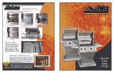
Clearances
from combustible
materials needed
per manufacturer
recommendation
- 4" Minimum clearance
recommended for media
- 12 - 13" Minimum clearance
below plate required for
electronic ignition
(H)
Fire Pit Cavity Components
A - GFCI Outlet (by others)
B - Location for remote
receiver (Optional)
C - Pigtail plug included for
easy installation
D - Electronics Box (Houses
120V - 24V Transformer)
E - 24V Power From
Transformer to Gas Valve
F - Gas Valve / Control Box
G
1
- Wires to Pilot
G
2
- Gas to Pilot
H - Gas Valve Supply IN
I - Gas Stub from source
(by others)
CROSSFIRE™
Brass Burner
Enclosure
constructed of all
non-combustible
materials
36"
(C)
10"
(I)
(B)
Recommended 18 sq.
inches of venting, or
equivalent, on
OPPOSING sides of fire
pit. (36 inches total)

4
GENERAL WARNINGS
WARNING: YOU MUST READ OWNERS MANUAL IN ITS ENTIRETY PRI-
OR TO INSTALLATION AND/OR OPERATION.
WARNING: FOR OUTDOOR USE ONLY.
WARNING: Improper installation, adjustment, alteration, service, or
maintenance can cause injury or property damage. Read the installation,
operating, and maintenance instructions thoroughly before installing or
servicing this equipment.
WARNING:
liquids in vicinity of this or any other appliance.
WARNING: LP-cylinder not connected for use shall not be stored in the
vicinity of this appliance.
WARNING: If you smell gas:
• Shut off gas to appliance.
•
• If gas odor continues, keep away from appliance and immediately
WARNING: DO NOT USE OXYGEN MIXERS WITH CROSSFIRE
TM
BRASS BURNERS. Mixers create leakage in the cavity of the pit and are a
serious hazard.
GENERAL INFORMATION
Carefully follow the instructions in this manual to prevent personal injury or
property loss. Instructions are updated as needed. It is the installer’s respon-
sibility to periodically review instructions for applicable updates.
WARNING: This Owner’s Manual contains critical information for the safe
tions must be strictly followed for safe installation and operation. Warranty is
void if not followed.
WARNING: It is the installer’s responsibility to ensure a safe installation and
to educate the end user as to proper operation. Installer must leave this
manual with the end user.
WARNING: We suggest that our products be installed by professionals
that are locally licensed by the authority having jurisdiction in gas piping.
We suggest that our products be serviced annually by a licensed plumber.
Installer must follow all instructions carefully to ensure proper performance
and safety. Warming Trends
TM
is not responsible for your actions.
WARNING:
damage the product and cause harm to the end user. Warranty is void if any
WARNING: FOR REMOTE CONTROL USE: To prevent accidental startup
from unwanted Remote Control signals it is the responsibility of the end user
to turn off power to electric outlet for the remote-control receiver when the
WARNING: Product is not intended to be a starter for wood or other combus-
tibles.
WARNING: It is the responsibility of the installer to follow ALL LOCAL
sence of local codes, please follow:
• Fixed piping system: The National Fuel Gas Code, ANSI Z223.1/
NFPA 54 or International Fuel Gas Code.
• Electrical ground: The National Electrical Code, ANSI/NFPA 70.
WARNING:
burner. Verify correct gas/fuel type and pressure. Never use an alternative
alternative fuel other than Liquid Propane or Natural Gas.
WARNING: Gas pressure and type should be checked prior to use and
installation.
SELECTING A LOCATION FOR YOUR FIRE FEATURE
WARNING:
tion systems are designed and intended for outdoor use only.
WARNING: For electronic ignition models, there must be an electrical
cent wall to allow for emergency shutdown and maintenance. Distance
may be determined by local code.
WARNING:
pit to allow for emergency shut off and maintenance.
WARNING:
not familiar with its operation or emergency shut off locations.
WARNING: Both children and adults should be alerted to the hazards
of high surface temperatures and should remain a safe distance away to
avoid burns and clothing ignition.
WARNING: Young children should be carefully supervised when they are
WARNING:
WARNING: Fire pits create very high temperatures - Combustibles must
be located far enough away that there is no risk of ignition.
IMPORTANT: It is recommended that material such as granite, marble or
pit material for any reason.
FIRE PIT CLEARANCES
• 36” horizontally from any combustible structure.
• Overhead clearance should be a minimum of 120” from com-
bustible structures.
• Choose a location that allows easy access for installation and
•
• Always consult with local municipality regarding any local code
requirements
MATCH LIGHT Minimum Maximum
Natural Gas 3.5” W.C. 7.0” W.C.
Liquid Propane 11.0” W.C. 13.0” W.C.
3V - 3VIK Minimum Maximum
Natural Gas 4.5” W.C. 10.0” W.C.
Liquid Propane 11.0” W.C. 13.0” W.C.
STANDARD - 24VIKSC
& 24VIKHC
Minimum Maximum
Natural Gas 3.0” W.C. 5.0” W.C.
Liquid Propane 8.0” W.C. 12.0” W.C.
PREMIUM - P24VIKSC
& P24VIKHC
Minimum Maximum
Natural Gas 3.5” W.C. 14.0” W.C.
Liquid Propane 8.0” W.C. 14.0” W.C.

5
CONSTRUCTION OF ENCLOSURE
WARNING: Mount the key valve on the outside exterior of enclosure, away
WARNING:
pit to allow for emergency shut off and maintenance.
WARNING: Key valve should be mounted below the plate line and
cian for proper installation.
WARNING: For electronic ignition models, there must be an electrical shut
to allow for emergency shutdown and maintenance. Verify correct power
supply.
WARNING: Always use proper materials and construction for gas supply,
power and enclosure. Materials must be non-combustible in both initial
installations as well as over time.
WARNING: For electronic ignition models requiring power supply – a
rated GFCI Receptacle outlet should be installed on the interior of the
enclosure above grade to supply power to system.
WARNING: Minimum requirement: Incorporate 1 vent on at least two
opposing sides (2 vents total) at a minimum size of 18 sq. inches each (Ex-
ample: 3”x 6” or larger). Installation of the vents in the mid to lower area of
the enclosure is recommended. Ventilation allows for heat and/or residual
overheating or explosion. Overheating could lead to heat damage to in-
ternal components. Some enclosures may require more ventilation based
on material, size, and extended use. The vent may serve as a drain as well
when installed at bottom sidewall to prevent water build up. Always con-
sult with local municipality regarding any local code requirements
WARNING: The interior space of the enclosure surrounding the valve box
WARNING:
require deeper recession.
WARNING: The enclosure must be constructed on a stable surface. The
not by any control/valve box. For electronic ignition models the control/
valve box must be above grade with adequate drainage to prevent water
damage to the controls inside the box. Installer is responsible for ensuring
there is enough space for electronics – see technical drawings provided by
manufacturer. Installer is responsible to ensure that the structure is level.
Blocks, bricks or L-brackets can be used to build a support ledge for the
system plate or pan.
WARNING: It is the responsibility of the installer to provide proper installa-
tion to allow for easy accessibility for service and/or repairs. Installer must
not build capstone inner ledge over outer lip of plates or pans (unless ac-
cess panel door or alternate access is incorporated). Building capstone in-
ner ledge over outer edge of plates or pans will impede access to system
and result in the need to crack capstones to gain access. Warming Trends
is not responsible for damage to enclosure for any reason whatsoever.
WARNING: Ready-to-
Finish Kits come with Fire
Pit Vent Kit (FPVK). Vents
do not come pre-installed
on Ready-to-Finish Kit as
placement and installation
depends on veneer.
Vents to be installed by
contractor on site.
GENERAL FIRE PIT INSTALLATION
WARNING:
WARNING:
sionals that are locally licensed by the authority having jurisdiction in gas
piping.
WARNING: We suggest that our products be serviced annually by a
licensed plumber.
WARNING: It is the installer’s responsibility to follow installation instruc-
tions carefully in order to ensure a safe installation, safe operation and
safe ongoing servicing.
WARNING:
Gas or Liquid Propane. Do not use Natural Gas appliance with Liquid Pro-
pane or Liquid Propane appliance with Natural Gas. Refer to the labeling
WARNING: Fuel line sizing is the responsibility of the installer and must
be able to supply the stated maximum BTU listed for each product.
WARNING: Gas Plumbing Connections: Use only joint compound or
WARNING:
WARNING: Before use, be sure to test all gas connections for leaks. Do
to repair.
WARNING:
and/or decorative glass and/or any covering material including log sets,
the instructions for Media must be followed.
WARNING: For electronic ignition systems, which have an extended
or detached valve box, the area in which the valve box is installed must
conform with all installation requirements, including but not limited to
location, construction, venting and local codes. Failure to do so may result
in personal injury, property damage or explosion.
WARNING: If using an LP bottle/tank, position bottle/tank at safe dis-
WARNING: Use only the key provided to turn the gas valve. Use only
hand strength to turn the gas key valve. Never use tools to turn the gas
valve. If key valve will not turn by hand, do not try to repair it. Contact a
1. Verify correct gas type (gas supply should match burner type.)
2. Verify correct pressure.
3. Purge gas lines of air, water and debris.
4. Perform all leak test with leak detector or leak reactant on main
gas supply and repair leaks as necessary.
5.
install proper power supply following all local codes.
6.
7.
8.
line to prevent whistling.
9. Position burner safely with access to all gas connections for testing.
10. Turn on gas supply and perform leak test on all connections and re-
11. Light burner.
12. For electronic ignition models, apply proper power supply.
Electronic Ignition models can either be hard wired into main
power supply or plugged into NEMA Rated, above grade, out-
that electrical supply be connected through on/off switch. No
dimmers. Can be used in combination with remote controls.
13.
Repair as needed.

6
MEDIA INSTALLATION
WARNING: Only use approved decorative media (glass, lava rock, ceramic log sets, etc.)
that have been manufactured for specific use in fire features.
WARNING: Media must be ½” or larger in size to prevent media from falling into gas
orifices and blocking flow of gas out of jets. Use approved media only.
WARNING: Burner and jets can be covered by ¼” to ½” of media above jets. PLEASE
NOTE - covering over jets more than ¼” to ½” may create back pressure and gas leak-
age through air cross holes resulting in pooling of gas under the fire feature which can
result in explosion. Also note that flame pattern will be affected by any media coverage
over gas orifice jets up to and including smothering of flames.
WARNING: When using electronic ignition systems please pay particular attention to
keeping media away from the pilot assembly area and/or away from wind screen of pilot
assembly. Incorrect media installation that blocks pilot assembly will cause the pilot flame
to suffocate, blocking of thermal sensor and/or a delay in main burner ignition.
WARNING: The fire pit is designed to use approved media that is correctly installed
over the burner to achieve proper combustion. Use of any media outside of the ap-
proved media sold by Warming Trends may void warranty and effect proper operations.
Install enclosure and fire feature per in-
structions provided by manufacturer.
Apply media per instructions by
then pushing media towards the gas
be sure no media has fallen into gas
For All Electronic Ignition Systems: Keep pilot assembly screen free and clear of
all media. Media should be piled no more than halfway up screen only (not over
For Ceramic Log Sets: Place logs on
top of lava rock base according to
For electronic ignition systems - do not
block, cover or obstruct pilot assembly.
Blocking, covering or placing ceramic
logs too close to pilot may cause ex-
cessive heat on pilot causing system to
fail. This is not covered under warranty.
14.
15. Set burner into properly constructed enclosure.
16. Apply media as per installation instruction.
17.
18. Review safety manual with end user and instruct end user not to
19. Leave manual with end user.
WARRANTY REQUIREMENT: Warranty is void if valve box
for any/all electronic ignition system is opened or tampered with
in any way. See warranty section for full warranty requirements.
FIRE FEATURE OPERATION
WARNING:-
sion may result causing property damage, personal injury, or loss of life.
WARNING: Before use, be sure to test all gas connections for leaks. Do
-
pected, turn off the main gas supply and repair.
WARNING:
WARNING: Do not place LP bottle inside enclosure.
WARNING: Use only your hand to turn the gas key valve. Never use tools.
WARNING:
WARNING:
WARNING: Never use any material for media that is non-porous and
holds moisture such as gravel, pebbles, river rock, etc. This material, when
heated will cause the trapped moisture to boil, fracture unexpectedly and/
or explode and cause personal injury or damage.
WARNING:
WARNING:
Make sure that there is no vegetation or other objects over the top or sides
-
WARNING:
WARNING: For electronic ignition systems – power supply must be turned
WARRANTY REQUIREMENT:-
LIGHTING INSTRUCTIONS FOR:
Match Light / Manual Light (no electronics) / Push Button Ignition
1. STOP! Read all the safety information and warnings in the owner’s
1.
debris such as leaves or other combustible material has not collect-
ed inside the feature which could burn and emit embers once the
feature.
2. Turn key valve clockwise slightly and then turn counterclockwise
to the OFF position.
2. Wait (5) minutes to clear out any gas. Then smell for gas.
3. If you smell gas, STOP!
4. Shut off gas to appliance.
5.
6. If gas odor continues, keep away from appliance and immediately
7. If you do not smell gas, turn key valve slowly counterclockwise to
the ON position while igniting lighter simultaneously to ignite gas.
8. For Push Button: Press push button ignition and listen for clicking noise
WARNING:
to the OFF position and call your service technician or gas supplier.
TO TURN OFF GAS APPLIANCE
1. Turn key valve clockwise until it stops.
2.
3. If using LP bottle/tank – turn bottle/tank to CLOSED position
4.
water proof / weather proof cover.

7
LIGHTING INSTRUCTIONS FOR:
3V Battery Operated System, 24V Premium Electronic Ignition System
& 24V Standard Electronic Ignition System
1. STOP! Read all the safety information and warnings in the owner’s
2. Before operating appliance ensure the manual gas shutoff valve is open.
3.
debris such as leaves or other combustible material has not collected
4.
Sequence of Operation during Ignition
• Power is applied.
• For 24V Premium System - Hot Surface Igniter / Glow Plug becomes
hot and 4 – 5 seconds later the Pilot Gas Valve opens.
• For 3 Volt Battery Operated System & 24V Standard System - Spark
Igniter will spark repeatedly and 4 – 5 seconds later the Pilot Gas
Valve will open.
• Within 10 seconds of power application Pilot Flame should be light-
ed and visible. (Visible at night only.)
• Within 10 seconds of Pilot Flame Ignition CROSSFIRE™ Brass Burner
should ignite .
TO TURN OFF ELECTRONIC IGNITION GAS APPLIANCE
1. -
ture - this can be done with remote control or switch.
2.
3. Turn off key valve to cut gas off manually per Manual Light instructions.
4. If using LP bottle/tank – turn bottle/tank to CLOSED position
5.
water proof / weather proof cover.
WARNING:
still visible), turn off gas supply using the manual gas shutoff.
MAINTENANCE
WARNING: Any guard or protective device removed for servicing must be
WARNING:
pits should be inspected prior to each use and inspected at least once annually
WARNING:
before servicing.
Keep re pit covered at all times when not in use.
lighting system.
In some areas of the country, spiders or insects have been known to build nests
CROSSFIRE
TM
shapes or behavior, or if burner fails to ignite properly, then the burner holes
cleaned by carefully removing the logs and media to allow access to burner. Use
a brush to carefully remove dust, spider webs and loose particles. Use a wire or
puncture tool and carefully insert in jet. Tool should be size of a small paper clip.
If evidence of damage, burner must be replaced with the appropriate CROSS-
FIRE
TM
Thermocouple Cleaning of Soot: Every six months or as needed. Remove lava
rock & glass around pilot, then the wind cage (screen around the pilot). Clean
thermocouple of any soot using soft brush. Be careful not to damage the hot wire
element. Place lava rock or glass back as explained in the Section Media Installa-
tion in Owners Installation Manual.
Visual inspection of pilot and pilot assembly: The pilot assembly should be free
TROUBLESHOOTING – MANUAL LIT / PUSH BUTTON
Below are some potential causes and countermeasures to the symptoms listed:
• Make sure the key valve is on. Turn key counterclockwise to open valve and
Low or Weak Flame
• Verify correct gas pressure.
One or more jets will not light.
• Check jets for obstruction.
Fire feature is making a whistling sound.
• Make sure that the flex line is the correct size and that there are no kinks in the line.
Contact a certified gas technician for service & repair if these suggestions do not solve the issue.
TROUBLESHOOTING - ELECTRONIC IGNITION SYSTEMS
Below are some potential causes and countermeasures to the symptoms below.
No Pilot Flame (Pilot sparks or glow plug glows but pilot won’t light)
• Air is in the gas line. If this is a new install it may take several attempts to purge the air.
• Debris is in the gas line. Clear the gas line.
• Water/Moisture is in the gas line. Clear the gas line.
•
•
• Electrical current is not strong enough to support igniter – either spark on
• Improperly applied media.
• Wind conditions might be too severe.
No Main Burner (Pilot Lights but main burner will not light)
•
•
• Dirty thermal sensor. Clean using soft brush.
• -
Main Burner Turning On and Off Intermittently
•
• Improperly applied media. See the Section “Media”.
•
• Thermal sensor is dirty or defective. Clean thermal sensor. Or change the pilot assembly.
• Wind conditions might be too severe.
Fire Feature is Making a Whistling Sound
•
tight bends in the line.
If replacement parts are required – contact your authorized dealer for authorized re-
placement parts. Using unauthorized parts may cause damage to the unit and/or cause
catastrophic failure of the unit. Warranty is null and void if unauthorized parts are used.
suggestions do not solve the issue.
and clear of any debris, dust, spider webs and loose particles from the media and
Push Button Only: Visually inspect electrode and jet used for conductivity regularly
to make sure it is free of debris and soot. Soot build up or obstructions of any kind
can reduce effectiveness of spark. Without a strong spark, burner will not light. If
grit sand paper, gently remove any rust from electrode. If spark is still not strong
problem, replace spark electrode. (See glossary for replacement part number.)

8
WARRANTY
ALL BURNERS AND ELECTRONICS (IF PRESENT) MUST BE COVERED
WHEN NOT IN USE OR WARRANTY IS NULL AND VOID
Warming Trends™ warrants its products to be free from defective materi-
al and workmanship under normal service and use. This warranty covers
manufacturing defects only and does not cover defects due to normal
wear and tear; it does not warrant any product or part that has been al-
tered, accidentally damaged, damaged in shipping, disassembled, mod-
continuous service after installation. Warming Trends™ liability shall be
restricted to the purchase price of the product only and makes no other
warranty, express or implied, but not limited to, the implied warranties of
products and parts, whether used along or in combination with others.
Warming Trends™ is free of liability for any damages caused by the unit,
as well as inconvenience expenses, material or labor charges incurred by
any service call, repair, removal or re-installation of any unit. Incidental or
consequential damages are not covered by this warranty. Warranty does
not cover damage to systems due to debris in the gas lines or damage to
system due to water. Owner is responsible for reading and understanding
warranty for full terms and conditions
Warming Trends™, at its discretion, agrees to repair or replace defective
product if returned to Warming Trends™ within the warranty period. The
respective warranty time periods are effective from the original date of
purchase. The warranty is non-transferable and applies only to the origi-
nal purchaser. In addition, this warranty is automatically void if the unit’s
serial number has been removed or altered in any way.
Ignition Systems Warranty
ALL BURNERS AND ELECTRONICS MUST BE COVERED WHEN NOT IN
USE OR WARRANTY IS NULL AND VOID
Push Button Ignition Systems
There is no warranty offered on any push button ignition system.
Electronic Ignition Systems
RESIDENTIAL INSTALLATIONS:
24VIK and 3VIK systems are fully warranted for one (1) year with a limited
warranty for two (2) years from date of purchase. In the event a system
must be replaced due to a defect/malfunction of the system, Warming
within two years from date of purchase, Warming Trends™will repair or
replace the system for a cost of 50% of the current list price. This warranty
does not cover labor costs.
P24VIK systems purchased ON OR BEFORE April 15, 2018 are fully
warranted for one (1) year with a limited warranty for two (2) years from
date of purchase. In the event a system must be replaced due to a defect/
malfunction of the system, Warming Trends™ will repair or replace the
year and within two years of date of purchase, the cost for a replacement
system is at a discount rate of 50% of the current listed price. This warran-
ty does not cover labor costs.
P24VIK Systems purchased AFTER April 15, 2018 are fully warranted
for three (3) years from date of purchase. In the event a system must be
replaced due to a defect/malfunction of the system, Warming Trends™
warranty does not cover labor costs.
COMMERCIAL INSTALLATIONS:
24VIK and 3VIK systems are fully warranted for six (6) months from date
of purchase. In the event a system must be replaced due to a defect/
malfunction of the system, Warming Trends™ will repair or replace the
system at no cost. This warranty does not cover labor costs.
P24VIK systems purchased ON OR BEFORE April 15, 2018 are fully
warranted for six (6) months from date of purchase. In the event a system
must be replaced due to a defect/malfunction of the system, Warming
Trends™ will repair or replace the system at no cost. This warranty does
not cover labor costs.
P24VIK Systems purchased AFTER April 15, 2018 are fully warranted
for one (1) year from date of purchase. In the event a system must be
replaced due to a defect/malfunction of the system, Warming Trends™
will repair or replace the system at no cost for 12 months from the date of
purchase. This warranty does not cover labor costs.
__________________________________________________________________
EXAMPLE OF SERIAL NUMBER LABELS (Example only - actual
label may vary)
Problems in the functioning of the systems due to gas plumbing or
electrical installed by others are not covered by any warranty offered by
Warming Trends.
No dealer, distributor, or other person has the authority to represent
or warrant a Warming Trends™ product beyond the terms contained
within this warranty, and Warming Trends™ assumes no liability for such
warranty representations. Any questions concerning this warranty should
Return Policy of Warranty Product
Any Warming Trends™ product deemed by Warming Trends™ as defec-
tive and covered by the warranty may be returned to Warming Trends™
for assessment to determine if repair or replacement is necessary. In
order to return a product, you must have a Return Merchandise Authori-
zation number (RMA#). Please contact a Warming Trends™ representa-
must have the RMA# clearly printed on the outside of the package. Re-
turn shipping costs are the purchaser’s responsibility. Warming Trends™
is not responsible for product damaged or lost in transit. It is recom-
mended that return items are shipped via a delivery service that can be

9
WARNING: Minimum requirement: Incorporate 1 vent on at least two opposing sides (2 vents total) at a minimum size of 18 sq. inches each (Example:
3”x 6” or larger). Installation of the vents in the mid to lower area of the enclosure is recommended. Ventilation allows for heat and/or residual fuel to
-
nents. Some enclosures may require more ventilation based on material, size, and extended use. The vent may serve as a drain as well when installed at
bottom sidewall to prevent water build up. Always consult with local municipality regarding any local code requirements.
WARNING: Ready-to-Finish Kits come with Fire Pit Vent Kit (FPVK). Vents do not come pre-installed on Ready-to-Finish Kit as placement and installation
depends on veneer. Vents to be installed by contractor on site.
60K – 120K BTU System with ½" Flex Line (FLKV12)
Original Series: CFB60, CFB84, CFB120 | Linear Series: CFBL90, CFBL110 | H-Style Series: CFBH120
Any custom burners between 60K - 120K
FOR PUSH BUTTON IGNITION INSTRUCTIONS:
to page 26 for Push Button Ignition installation instructions.
•
• Plumb your existing gas supply into one side of your key valve.
•
brackets, etc.)
•
• For Match Lit burners, Warming Trends
TM
recommends a minimum 6” clearance below plate for
additional connections.
• For Electronic Ignition burners, Warming Trends
TM
for additional connections.
•
• Be sure to tighten every joint securely. Use thread sealant where required.
•
BRASS BURNERS
60K – 120K BTU System with FLKV12
4” Key
12” Key
Key ValvePressure
Face Plate
Flex Line
STEP 1: Locate FLKV12

10
STEP 2:
STEP 3A: (FOR MATCH LIT SYSTEM)
Step 2 to the ½” coupling located on the bottom
Tighten.
Apply thread
sealant here
Plate
Coupling
Flared Fitting
STEP 3D
STEP 3D: (PREMIUM 24 VOLT IGNITION)
Coupling
Flared
Fitting
Premium 24 Volt
Ignition
Drip Leg
Plate
Apply thread
sealant here
STEP 3C
STEP 3C: (STANDARD 24 VOLT IGNITION)
Coupling
Standard 24 Volt
Ignition
Flared
Fitting
Drip Leg
Plate
Apply thread
sealant here
STEP 3B
STEP 3B: (3 VOLT IGNITION)
Coupling
3 Volt Ignition
Flared
Fitting
Drip Leg
Plate
Apply thread
sealant here
60K – 120K BTU System with FLKV12
Flared Fitting
Flex Line

11
STEP 5
STEP 5:
in Step 2 and connect into the ½” key valve, placing
Apply thread
sealant here
Flared Fitting
Key Valve
STEP 4A: (MATCH LIT SYSTEM)
on the bottom of your aluminum plate.
Coupling
Flex Line
Flared Fitting
STEP 4B: (3 VOLT IGNITION)
STEP 4b
Coupling
Flex Line
Plate
Flared
Fitting
3 Volt
Ignition
Drip Leg
STEP 4C: (STANDARD 24 VOLT IGNITION)
STEP 4C
Coupling
Flex LineFlared
Fitting
Standard
24 Volt
Ignition
Drip Leg
Plate
STEP 4D: (PREMIUM 24 VOLT IGNITION)
STEP 4D
Coupling
Flex LineFlared
Fitting
Premium
24 Volt
Ignition
Drip Leg
Plate
Plate
60K – 120K BTU System with FLKV12

12
STEP 6
Questions? Contact Warming Trends at 303.346.2224
STEP 6A: (MATCH LIT SYSTEM)
STEP 7: (STANDARD 24 VOLT AND PREMIUM 24 VOLT
IGNITION SYSTEMS ONLY)
Plug ignition into three prong, above grade, NEMA Rated,
hardwire ignition into transformer.
FINAL SET UP
STEP 6B: (3 VOLT IGNITION)
Drip Leg
Coupling
3 Volt Gas Valve
Flex Line
Plate
Flared
Fittings
Key Valve
Key In
Gas Line In
STEP 6C: (STANDARD 24 VOLT IGNITION)
Drip Leg
Coupling
Standard 24 Volt Ignition
Flex Line
Flared
Fittings
Plate
Key Valve
Key In
Gas Line In
STEP 6D: (PREMIUM 24 VOLT IGNITION)
Drip Leg
Coupling
Premium 24 Volt Ignition
Flex Line
Plate
Flared
Fittings
Key Valve
Key In
Gas Line In
Coupling
Flex Line
Flared
Fitting
Plate
Key Valve
Key In
Flared
Fitting
Gas Line In
60K – 120K BTU System with FLKV12

13
121K - 249K BTU Systems with
¾" Flex Line (FLKV34) or
¾" Flex Line + FIT180 (FLKV34FIT180)
Original Series: CFB180 | Linear Series: CFBL130, CFBL150, CFBL190, CFBL210 | H-Style Series: CFBH160, CFBH200,
CFBH240 Any custom burners between 121K - 249K
FOR PUSH BUTTON IGNITION INSTRUCTIONS:
to page 26 for Push Button Ignition installation instructions.
STEP 3
STEP 3:
the inside threads
Apply thread sealant here
Use inside threads
of ared tting
STEP 2:
Flex Line
121K - 249K BTU Systems with FLKV34 and FLKV34FIT180
STEP 1 - FIT180
4” Key
12” Key
Key ValvePressure
Face Plate
Flex Line
STEP 1: Locate FLKV34
and FIT180.
WARNING: Minimum requirement: Incorporate 1 vent on at least two opposing sides (2 vents total) at a minimum size of 18 sq. inches each (Example:
3”x 6” or larger). Installation of the vents in the mid to lower area of the enclosure is recommended. Ventilation allows for heat and/or residual fuel to
-
nents. Some enclosures may require more ventilation based on material, size, and extended use. The vent may serve as a drain as well when installed at
bottom sidewall to prevent water build up. Always consult with local municipality regarding any local code requirements.
WARNING: Ready-to-Finish Kits come with Fire Pit Vent Kit (FPVK). Vents do not come pre-installed on Ready-to-Finish Kit as placement and installation
depends on veneer. Vents to be installed by contractor on site.

14
Apply thread
sealant here
Plate
Coupling
Flared Fitting
(FIT180)
STEP 4A: (MATCH LIT SYSTEM) Connect the
the bottom of the aluminum plate. Tighten.
STEP 4C
Drip Leg
STEP 4B: (STANDARD 24 VOLT IGNITION)
Apply thread
sealant here
Coupling
Standard 24 Volt Ignition
Flared Fitting
Plate
STEP 4C: (PREMIUM 24 VOLT IGNITION)
STEP 4D
Apply thread sealant here
Coupling
Premium 24 Volt Ignition
Drip Leg
Flared Fitting
Plate
(FIT180)
STEP 5A: (MATCH LIT SYSTEM) Connect
aluminum plate.
Coupling
Flex Line
Flared Fitting
STEP 5c
STEP 5B: (STANDARD 24 VOLT IGNITION)
Coupling
Flex Line
Flared Fitting
Standard 24 Volt Ignition
Drip Leg
Plate
(FIT180)
STEP 5d
STEP 5C: (PREMIUM 24 VOLT IGNITION)
Coupling
Flex Line
Flared Fitting
Premium 24 Volt Ignition
Drip Leg
Plate
(FIT180)
121K - 249K BTU Systems with FLKV34 and FLKV34FIT180
Plate

15Questions? Contact Warming Trends at 303.346.2224
STEP 7A: MATCH LIT SYSTEM
FINAL SET UP
STEP 8: (STANDARD 24 VOLT AND PREMIUM 24 VOLT IGNITION SYSTEMS ONLY)
hardwire ignition into transformer.
Coupling
Flex Line
Flared
Fitting
Plate
Key Valve
Flared
Fitting
Gas In
Key In
STEP 7B: (STANDARD 24 VOLT IGNITION)
Coupling
Key Valve
Plate
Standard 24 Volt Ignition
Drip Leg
Gas Line In
Key In
Flex Line
Flared
Fittings
(FIT180)
STEP 7C: (PREMIUM 24 VOLT IGNITION)
STEP 7d
Coupling
Key Valve
Plate
Standard 24 Volt Ignition
Drip Leg
Gas In
Key In
Flex Line
Flared
Fittings
(FIT180)
STEP 6:
removed in Step 3 and connect into the ¾” key
valve. Tighten using crescent wrench.
STEP 5
Apply thread
sealant here
Flared Fitting
Key Valve
121K - 249K BTU Systems with FLKV34 and FLKV34FIT180

16
250K - 299K BTU Match Lit System with
¾" Dual Flex Lines (DFLKV34) or
¾" Dual Flex Lines + FIT250 (DFLKV34FIT250)
Original Series: CFB250, CFB290 | Linear Series: CFBL250, CFBL270
Any custom burners between 250K - 299K
NOTE: If using the Standard 24 Volt High Capacity Ignition, turn to page 25 for instruction on installation. Burners
between 250K - 300K BTU's using a Standard 24 Volt Ignition will need to use the FIT300. Turn to page 20 for installation
instructions.
FOR PUSH BUTTON IGNITION INSTRUCTIONS:
to page 26 for Push Button Ignition installation instructions.
STEP 1- FIT250
STEP 1- FIT250
STEP 1- FIT250
STEP 1: Locate DFLKV34 and FIT250
(4” and 12”) plus FIT250 Kit.
4” Key
12” Key
Key ValvePressure
Face Plate
Flex Lines
250K - 299K BTU Systems with DFLKV34 and DFLKV34FIT250
WARNING: Minimum requirement: Incorporate 1 vent on at least two opposing sides (2 vents total) at a minimum size of 18 sq. inches each (Example:
3”x 6” or larger). Installation of the vents in the mid to lower area of the enclosure is recommended. Ventilation allows for heat and/or residual fuel to
-
nents. Some enclosures may require more ventilation based on material, size, and extended use. The vent may serve as a drain as well when installed at
bottom sidewall to prevent water build up. Always consult with local municipality regarding any local code requirements.
WARNING: Ready-to-Finish Kits come with Fire Pit Vent Kit (FPVK). Vents do not come pre-installed on Ready-to-Finish Kit as placement and installation
depends on veneer. Vents to be installed by contractor on site.

17
STEP 3A:
to the ½” coupling located underneath the
aluminum plate.
Apply thread sealant here
Reducing
Fitting (FIT250)
Reducing
Fitting (FIT250)
Coupling
Plate
STEP 3B: (STANDARD 24 VOLT
HIGH CAPACITY IGNITION)
SEE PAGE 20 FOR
INSTALLATION
INSTRUCTION
STEP 3c
STEP 3C: (PREMIUM 24 VOLT STANDARD CAPACITY IGNITION)
Coupling
Apply thread
sealant here
Drip Leg
Plate
Premium 24 Volt Stan-
dard Capacity Ignition
STEP 2:
STEP 2
Flared Fitting
Flared Fitting
Flared Fitting
Flared Fitting
250K - 299K BTU Systems with DFLKV34 and DFLKV34FIT250

18
STEP 5B: (STANDARD 24 VOLT HIGH CAPACITY IGNITION)
SEE PAGE 20 FOR
INSTALLATION
INSTRUCTION
STEP 5A:
underneath aluminum plate.
Coupling
Flared Fitting Flared Fitting
Apply thread
sealant here
Apply thread
sealant here
¾” Tee (FIT250)
STEP 5c
STEP 5C: (PREMIUM 24 VOLT STANDARD CAPACITY IGNITION)
Coupling
Flared Fitting
Flared Fitting
Apply thread
sealant here
Premium
24 Volt
Standard
Capacity
Ignition
Drip Leg
¾” Tee
(FIT250)
Plate
Plate
STEP 4A:
connection made in Step 3 (½” x ¾” reducing
STEP 4
Apply thread sealant here
Coupling
STEP 4B: (STANDARD 24 VOLT HIGH CAPACITY IGNITION)
SEE PAGE 20 FOR
INSTALLATION
INSTRUCTION
Plate
STEP 4c
Coupling
(FIT250)
STEP 4C: (PREMIUM 24 VOLT STANDARD CAPACITY IGNITION)
Apply thread
sealant here
Plate
Drip Leg
Premium
24 Volt
Standard
Capacity
Ignition
Apply thread
sealant here
250K - 299K BTU Systems with DFLKV34 and DFLKV34FIT250
Reducing
Fitting (FIT250)
Fitting (FIT250)
Fitting (FIT250)
Reducing
Fitting (FIT250)

19
STEP 6c
STEP 6A:
Coupling
Flex Line Flex Line
¾” Tee (FIT250)
Flared Fitting Flared Fitting
Drip Leg
Plate
Flex Line
Flex Line
STEP 6C: (PREMIUM 24 VOLT STANDARD CAPACITY IGNITION)
Coupling
Flared
Fitting
Premium 24 Volt Standard
Capacity Ignition
¾” Tee
(FIT250)
STEP 6B: (STANDARD 24 VOLT HIGH CAPACITY IGNITION)
SEE PAGE 20 FOR
INSTALLATION
INSTRUCTION
Key Valve
STEP 9:
STEP 9B: (STANDARD 24 VOLT IGNITION)
Same as above.
STEP 9C: (PREMIUM 24 VOLT IGNITION)
Same as above.
Flared Fitting
Flared Fitting
Apply thread sealant here
Apply thread sealant here
3” x ¾”
Pipe Nipple
(FIT250)
Key Valve
¾” Tee (FIT250)
STEP 8:
(FIT250) to the connection made in Step 7.
STEP 8B: (STANDARD 24 VOLT IGNITION)
Same as above using FIT300.
STEP 8C: (PREMIUM 24 VOLT IGNITION)
Same as above using FIT250.
Apply thread
sealant here
¾” Tee
(FIT250)
3” x ¾”
Pipe Nipple
(FIT250)
STEP 7A: Connect ¾” x 3” pipe nipple
(FIT250) to the ¾” key valve.
STEP 7B: (STANDARD 24 VOLT IGNITION)
Same as above.
STEP 7C: (PREMIUM 24 VOLT IGNITION)
Same as above.
Apply thread
sealant here
Key Valve
3” x ¾”
Pipe Nipple
(FIT250)
Flared
Fitting
250K - 299K BTU Systems with DFLKV34 and DFLKV34FIT250
Reducing
Fitting (FIT250)
Reducing
Fitting (FIT250)

20 Questions? Contact Warming Trends at 303.346.2224
STEP 10A: Connect
available ends of ¾”
aluminum plate in Step
connected in Step 10.
STEP 10C: (PREMIUM 24 VOLT STANDARD CAPACITY IGNITION)
3” x ¾”
Nipple
(FIT250)
Drip Leg
Coupling
Premium
24 Volt
Standard
Capacity
Ignition
(FIT250)
(FIT250)
Flared
Fitting
Flared
Fitting
Flared
Fitting
Flared Fitting
Flex Line
Flex Line
Key Valve
Key In
Gas In
STEP 11: (STANDARD 24 VOLT AND PREMIUM 24 VOLT IGNITION SYSTEMS ONLY)
hardwire ignition into transformer.
FINAL SET UP
Coupling
Flared
Fitting
Flared
Fitting
Flex Line Flex Line
Plate
Key Valve
Gas In
Key In
3” x ¾” Pipe Nipple (FIT250)
¾” Tee
(FIT250)
STEP 10B: (STANDARD 24 VOLT
HIGH CAPACITY IGNITION)
SEE PAGE 20 FOR
INSTALLATION
INSTRUCTION
250K - 299K BTU Systems with DFLKV34 and DFLKV34FIT250
Reducing
Fitting (FIT250)
/