Ocean Aire OWC6012 Engineering, Installation And Service Manual
- Category
- Split-system air conditioners
- Type
- Engineering, Installation And Service Manual
This manual is also suitable for


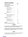
TABLE OF CONTENTS
PAGE
GENERAL INFORMATION…................................. 1
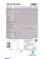
PRODUCT DATA AND SPECIFICATIONS............ 2
UNIT DESCRIPTION
Standard Features.................................. 3
Applications / Operation.......................... 4
Electrical Configurations......................... 5
Use of Extension Cords.......................... 6
Accessories……….................................. 7 - 11
Options / Special Order........................... 12
Installation............................................... 13
Electronic Controller................................ 14 - 16
SERVICE
Water Valve Adjustment, Unit Interior..... 17
Replacement Parts Procedure................ 18
Troubleshooting Guide............................ 19
Preventive Maintenance.......................... 20
DIAGRAMS
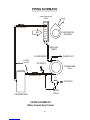
Piping Schematic..................................... 21
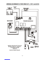
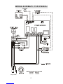
Single Phase Wiring Diagrams………….. 22-24
Three Phase Monitor............................... 25
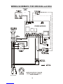
Three Phase Wiring Diagrams................ 26 - 28
WARRANTY………………………………………….. 29
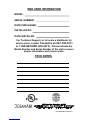
END USER INFORMATION AND TECH NOTES…. Back Page
FORWARD
This manual provides the user with basic details for the installation and operation of the
OceanAire OWC spot cooler. It is recommended to read and fully understand the
instructions outlined within this manual, before operating the OWC unit.
As with all commercial air conditioning equipment, it is recommended to have the OWC
sized and installed by a licensed specifying engineer and contractor, in accordance with
all local and state codes. The length of service received can be extended by following
the installation and preventive maintenance instructions.
NOTICE
In our ongoing process of continuous improvement, the items and procedures described
in this manual are subject to change without notice. Please note model and serial
number of the OWC unit when contacting the factory.

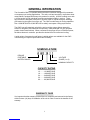
NOMENCLATURE
O WC 18 1 1
DELUXE
PORTABLE VOLTAGE
WATER-COOLED PHASE (1 or 3)
NOMINAL CAPACITY
CAPACITY RATING
12..........12,000 BTU/HR
18..........18,000 BTU/HR
24..........24,000 BTU/HR
36..........36,000 BTU/HR
60……...60,000 BTU/HR
GENERAL INFORMATION
The OceanAire OWC is a portable water-cooled air conditioner designed for permanent
or temporary spot cooling applications. The entire unit has been built in a premium sheet
metal cabinet, equipped with heavy-duty casters for mobility. All OWC models come with
a 10-foot power cord for electrical connection and added mobility in service. These
spot-coolers are designed to direct air to specific areas or objects through a discharge
grill located on the upper-front of the unit. The OWC models range in cooling capacities
from 12,000 BTU/HR to 60,000 BTU/HR to satisfy most space cooling requirements.
The OWC is a self-contained unit with the entire cooling system (blower assembly,
electrical, refrigerant, and waterside components), neatly arranged in a gray polyester
powder coated metal cabinet. When connected to the proper source of electrical power,
the deluxe electronic controller provides the desired level of comfort and cooling.
A wide variety of accessories and factory installed options are available for the OWC
units allowing for improved performance and versatility.
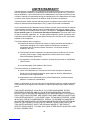
WARRANTY CARD
It is important that the warranty card be filled out completely and returned to the factory
within fourteen (14) days of installation of the unit in order to receive the benefits of the
warranty.
1


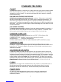
STANDARD FEATURES
CABINET
The OWC-Series cabinet is constructed of 18 gauge steel with a gray polyester powder coated
finish that will compliment any decor. The entire cabinet is insulated with sound- absorbing
insulation for cool, quiet comfort. All units come equipped with swivel casters for portability
and convenient set-up.
DELUXE ELECTRONIC CONTROLLER
All OWC units are equipped with a deluxe electronic controller. When power is connected to
the unit, the thermostat will control the unit to cool a space to the desired temperature. The
thermostat is also capable of controlling the fan to operate automatically (when needed), or
continuously. To protect the compressor from short-cycling, there is a built-in time delay in the
thermostat. In the event of a power outage, all thermostat settings are saved, and the unit will
re-start automatically.
FAN SPEED CONTROL
The deluxe electronic controller is capable of setting fan speeds automatically or manually. In
AUTO mode, the fan speed adjusts in accordance to cooling conditions. In MANUAL mode,
the fan speed can be maintained at any one of six speed levels, from low to high.
CONDITION ALARM—CON
The LED thermostat of the OWC will display the word “CON”. CON indicates a fault
condition that needs to be addressed:
CONDENSATE PUMP...disabled / restricted drain tube/routed incorrectly
WATER SUPPLY……….turned off / interrupted flow
EITHER CONDITION WILL TRIP THE HIGH PRESSURE SAFETY SWITCH. See below.
CONDENSATE PUMP
All OWC units come equipped with an Automatic Condensate Pump that removes the
condensate. The pump discharges through a 3/8 male flare DRAIN connection located on the
back of the unit. The pump is capable of pumping to a 20-foot height, to handle almost any
installation requirement.
HIGH PRESSURE (HP) SWITCH
Located on the back of the OWC unit is a manual re-set high pressure switch, used for the
protection of the compressor in the event that the condenser water supply is turned off. If the
condensing pressure exceeds the limit setting, the switch cycles off the compressor, while the
evaporator fan remains running, and the default “CON” will display on the controller. The high
pressure switch is also wired in series with the condensate pump. If a failure occurs with the
operation of the pump circuit, the HP switch will open. Once the water interruption/condensate
pump failure has been corrected, turn the unit off, reset the switch by depressing the red
RESET button on the back of the unit, and restart the unit.
FILTERS
All OWC units are equipped with a washable filter at the air intake. An electrostatic mesh air
filter is located behind the evaporator return air grille to filter the air before it is cooled,
keeping the coil free from dust build-up. The filter can be easily removed and cleaned.
POWER CORDS
All OWC units come standard with a power cord for a convenient connection. All
models, except for the 3-phase units and 5-ton units, are equipped with LCDI for
added safety features.
3

4
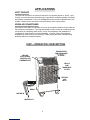
APPLICATIONS
SPOT COOLER
The OWC can be used in an open environment to cool specific objects or "spots". Spot
Cooling is a convenient and economical way to provide air conditioning where cooling the
entire space is impractical. Cool air is discharged from the unit and is directed where it is
needed. Nozzle kits can be used to improve direction of the cooling airflow.
ROOM AIR CONDITIONER
One feature of the OWC is it operates as a room air conditioner because it uses water as
the means for heat rejection. The major advantage of water-cooled air conditioning is the
convenience of connecting water hoses, or lines, as compared to the installation of
condenser air ducts used for air-cooled portables. A variety of hose kit lengths are
available that can be used for connecting to a water supply and drain, while providing
portability within the conditioned space.
RETURN
AIR
INLET
EVAPORATOR
FAN DISCHARGE
“COOL”
GRILLE
AND
WASHABLE
FILTER
DELUXE
ELECTRONIC
CONTROLLER
(THERMOSTAT)
DRAIN
WATER IN
WATER OUT
OWC—OPERATION / DESCRIPTION

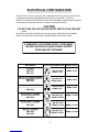
ELECTRICAL CONFIGURATION
All OWC Series units are equipped with a standard 10-foot long service cord with plug
configurations and receptacle requirements as shown in this chart. OWC1211,
OWC1811, OWC2412 and OWC3612 units come with LCDI (Leakage Current Detection
& Interruption) devices that serve as a means of electrical protection.
CAUTION
DO NOT USE THE LCDI AS AN ON/OFF SWITCH FOR THE UNIT
All 3-phase models are equipped with locking plugs for added connection reliability.
Refer to the chart below for plug and receptacle details for all OWC models.
UNIT/MODEL PLUG CONFIGURATION RECEPTACLE
115 VOLT
OWC1211
OWC1811
NEMA 5-15R
208-230 VOLT SINGLE PHASE
OWC2412
OWC3612
NEMA 6-20R
208-230 VOLT SINGLE PHASE
OWC6012
NEMA 6-30R
208-230 VOLT 3-PHASE
OWC3632
NEMA L15-20R
208-230 VOLT 3-PHASE
OWC6032
NEMA L15-30R
460 VOLT 3-PHASE
OWC3634
OWC6034
NEMA L16-20R
15A-125 VOLT
NEMA 5-15P
20A-250 VOLT
NEMA 6-20P
30A-250 VOLT
NEMA 6-30P
20A-250 VOLT
NEMA L15-20P
30A-250 VOLT
NEMA L15-30P
20A-460 VOLT
NEMA L16-20P
5
A DAMAGED LCDI POWER SUPPLY CORD MUST
BE REPLACED WITH A NEW POWER SUPPLY
CORD AND NOT REPAIRED

6
USE OF EXTENSION CORDS
CAUTION
FOR MODELS OWC1211 AND OWC1811 AN EXTENSION CORD CAN BE USED
PROVIDED IT IS RATED AT LEAST 15 AMPS @ 115 VOLTS WITH GROUNDING-
TYPE ATTACHMENT PLUG AND GROUNDING TYPE CONNECTOR (LOAD FITTING)
FOR MODELS OWC2412 and OWC3612 AN EXTENSION CORD CAN BE USED
PROVIDED IT IS RATED AT LEAST 20 AMPS @ 250 VOLTS WITH GROUNDING-
TYPE ATTACHMENT PLUG AND GROUNDING TYPE CONNECTOR (LOAD
FITTING)
FOR MODEL OWC6012 AN EXTENSION CORD CAN BE USED PROVIDED IT IS
RATED AT LEAST 30 AMPS @ 250 VOLTS WITH GROUNDING-TYPE ATTACHMENT
PLUG AND GROUNDING TYPE CONNECTOR (LOAD FITTING)
FOR MODEL OWC3632 AN EXTENSION CORD CAN BE USED PROVIDED IT IS
RATED AT LEAST 20 AMPS @ 250 VOLTS, 3 PHASE
FOR MODEL OWC6032 AN EXTENSION CORD CAN BE USED PROVIDED IT IS
RATED AT LEAST 30 AMPS @ 250 VOLTS, 3 PHASE
FOR MODELS OWC3634 AND OWC6034 AN EXTENSION CORD CAN BE USED
PROVIDED IT IS RATED AT LEAST 20 AMPS @ 600 VOLTS, 3 PHASE
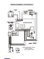
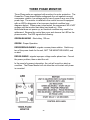
SPECIAL NOTICE—THREE PHASE OPERATION
Models OWC3632, OWC3634, OWC6032 and OWC6034
All three-phase OWC models are equipped with a three-phase monitor for
added compressor protection. The phase monitor, located in the control box,
has multi-color LED that reports status. The monitor protects the compressor
from reverse operation, phase loss and low voltage situations. Further descrip-
tion of the three-phase monitor is located in the electrical section of the manual.
NOTICE - DO NOT OPERATE ANY THREE-PHASE UNIT WHILE BY-
PASSING THE MONITOR. THIS WILL VOID THE WARRANTY.

7
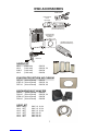
OWC ACCESSORIES
NOZZLE KIT
NK-1 (2 X 4-Inch) OWC12
NK-2 (2 X 6-Inch) OWC18, 24
2NK-3 (2 X 8-Inch) OWC36
NK-3 (2 X 8-Inch) OWC60
EVAPORATOR RETURN AIR PLENUM
DEP-10 (10-Inch Round) OWC12
2DEP-12 (12-Inch Round) OWC18, 24
DEP-16 (16-Inch Round) OWC36, 60
DISCHARGE DUCT ADAPTER
DDA-6 (6-Inch Round) OWC12
DDA-10 (10-Inch Round) OWC18, 24
2DDA-16 (16-Inch Round) OWC36
DDA-16 (16-Inch Round) OWC60
HOSE KIT
HK-1 10FT OWC 12, 18, 24
HK-2 25FT OWC 12, 18, 24
HK-5 40FT OWC 12, 18, 24
HK-3 10FT OWC 36, 60
HK-4 25FT OWC 36, 60
HK-6 40FT OWC 36, 60
HOSE KIT
NOZZLE KIT
DISCHARGE
DUCT
ADAPTER
ROUND FLEX-DUCT
(SOLD SEPARATELY)
ROUND FLEX-DUCT
(SOLD SEPARATELY)
EVAPORATOR
RETURN AIR
PLENUM

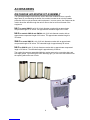
ACCESSORIES
DISCHARGE AIR NOZZLE KIT ASSEMBLY
The optional discharge nozzle kits are used to direct the conditioned air to a specific
target area. By concentrating the airflow, the nozzles increase the air velocity towards
production lines to cool personnel and/or equipment. In server rooms, the nozzles can be
used to direct the airflow through the rack to remove the hot air from the area of the
equipment.
NK-1 for model OWC12, with (2) 4-inch diameter nozzles with an approximate
compressed length of 15 inches. The approximate extended length is 21 inches.
NK-2 for models OWC18 and OWC24 with (2) 6-inch diameter nozzles with an
approximate compressed length of 22 inches. The approximate extended length is
32 inches.
2NK-3 for model OWC36 , with (2) 8-inch diameter nozzles with an approximate
compressed length of 20 inches. The extended length is approximately 29 inches.
NK-3 for OWC60, with (2) 8-inch diameter nozzles with an approximate compressed
length of 20 inches. The extended length is approximately 29 inches.
The nozzle kits come pre-assembled with the nozzles secured to a mounting plate, and
with edge guards. By removing the OWC discharge grill, you can insert the nozzle kit into
the opening without the use of tools.
8

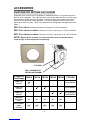
ACCESSORIES
EVAPORATOR RETURN AIR PLENUM
Evaporator return air plenums are available for installations where it is required to duct air to
the inlet of the evaporator. The evaporator return air plenums allow the user to connect round
duct (flexible or rigid) to the return air intake to reduce air noise and increase the number of
options for solving difficult cooling problems. The plenum attaches to the front of the unit,
replacing the return air grille. Refer to the table below for configuration and application infor-
mation
DEP-10 for OWC12 transitions the return air opening to a 10-inch round duct.
DEP-12 for OWC18 and OWC24 transitions the return opening to a 12-inch round duct.
DEP-16 for OWC36 and OWC60 transitions the return opening to a 16- inch round duct.
NOTE—When a DEP is installed, it is recommended to set the evaporator blower
speed to high, to avoid evaporator coil freeze-up.
Plenum Kit
Duct/Flange OWC12 OWC18 OWC24 OWC36 OWC60 FILTERS
DEP-10
10 inch (1) 10”X20”X1”
DEP-12
12 inch (1) 16”X24”X1”
DEP-16
16 inch (1) 10”X30”X1”
(1)15”X30”X1”
Maximum
Equivalent
Feet
25 50 50 50 100
Est. External
Static
Pressure
(.20) (.25) (.25) (.25) (.50)
FILTER(S)
DEP—EVAPORATOR
RETURN AIR PLENUM
9

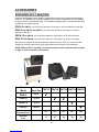
ACCESSORIES
DISHARGE DUCT ADAPTER
Discharge duct adapters are available for applications where ducted evaporator discharge is
required. The adapters can be easily installed on the unit without fasteners, and be installed
for either vertical or horizontal ducting. The standard discharge grille is removed and the DDA
is attached in the grille opening.
DDA-6 for OWC12, converts the evaporator discharge to a 6-inch diameter round duct.
DDA-10 for OWC18 and OWC24, converts the evaporator discharge to a 10-inch
diameter round duct.
2DDA-16 for OWC36, converts the evaporator discharge to a 16-inch round duct.
DDA-16 FOR OWC60, converts the evaporator discharge to a 16-inch round duct.
When used in conjunction with the evaporator return air plenum, DEP, the unit can provide
closed-loop cooling to and from a given space without the influence of any outside air.
NOTE—When a DDA is installed, it is recommended to set the evaporator blower speed
to high, to avoid evaporator coil freeze-up.
Adapter
Model
Round
Duct Size OWC12 OWC18 OWC24 OWC36 OWC60
DDA-6 6-inch
DDA-10 10-inch
2DDA-16 16-inch
DDA-16 16-inch
Maximum Approx.
Equivalent Feet 25 50 50 50 100
Maximum
E.S.P .15 .25 .25 .25 .50
10

ACCESSORIES
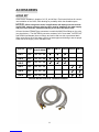
HOSE KIT
Hose kits are available in lengths of 10, 25, and 40 feet. Each hose kit allows for conven-
ient installation of the OWC, while allowing for portability within the allowable space.
NOTICE—When using these hoses in applications with water pressures exceed-
ing 50 PSIG, a water pressure reducing valve must be installed in the water supply
line prior to the hose kit; otherwise warranty on the hose kits will be void.
All hose kits have FEMALE flare connectors to match the MALE flare fittings on the units
(see chart below). The WATER IN connector consists of a 3/4” hose barb. WATER OUT
and DRAIN (condensate) have no fittings, and can be fed to a sink or permanent drain.
When using a hose kit, avoid sharp corners, hot water pipes and kinking to assure proper
water flow of the supply, return, and drain lines.
Hose Kit
Hose Kit Length Flare Conn
IN-OUT-DRAIN OWC12 OWC18 OWC24 OWC36 OWC60
HK-1 10 ft 3/8 3/8 3/8
HK-2 25 ft 3/8 3/8 3/8
HK-5 40 ft 3/8 3/8 3/8
HK-3 10 ft 5/8 5/8 3/8
HK-4 25 ft 5/8 5/8 3/8
HK-6 40 ft 5/8 5/8 3/8
11
Included with the hose kit is a sink/faucet adapter

12
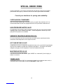
SPECIAL ORDER ITEMS
In some applications, units can be manufactured with optional components for added
performance and longevity. Below are a few of the OWC options that are available.
Consult your distributor for pricing and availability.
CUPRO-NICKEL CONDENSER
When chemically treated water, salt water or brine, is used in the condenser coil, it is
recommended that the OWC be equipped with a 90/10 Cupro-Nickel condenser coil.
HIGH PRESSURE WATER VALVE
For applications where water supply pressures exceed 150 psig, a high pressure water
regulating valve can be installed in the OWC. Valves designed for use with up to 350
psig water inlet pressure are available.
HERESITE TREATED EVAPORATOR COIL
For use in chemically corrosive environments, the OWC can be manufactured with a
Heresite® coated evaporator coil for improved coil life.
HOT GAS BYPASS VALVE
In applications where low evaporator temperatures may occur, an optional hot gas bypass
valve can be installed to regulate the evaporator temperature. The bypass valve feeds
refrigerant (hot gas) into the evaporator to avoid low ambient freeze-ups.
MARITIME WATER VALVE
Cast naval bronze body with MONEL parts. MONEL is a “natural alloy” and is highly re-
sistant to corrosion.
TOWER UNITS
In applications where the OWC is connected to a closed-loop condenser water circuit, a
unit can be built for direct water connection WITHOUT a water valve.

13
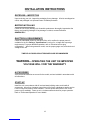
INSTALLATION INSTRUCTIONS
RECEIVING—INSPECTION
Upon receiving your unit, inspect the packaging for any damage. All units are shipped on
a skid, and packaged in a triple-wall carton for added protection.
BEFORE INSTALLING
Check the unit for any damage. All OceanAire products are thoroughly inspected at the
factory and carefully packaged. If any damage is evident, contact OceanAire
IMMEDIATELY.
ELECTRICAL REQUIREMENTS
Check the nameplate located on the back of the unit to confirm the proper power is
available for the unit. Refer to "Specifications" section for voltage and amperage
requirements. For proper NEMA receptacles, refer to "Electrical service plug
configuration". When using extension cords, use the proper gauge cord, and check cord
voltage to the unit.
TIME DELAY FUSES/CIRCUIT BREAKERS ARE RECOMMENDED
WARNING—OPERATING THE UNIT ON IMPROPER
VOLTAGE WILL VOID THE WARRANTY
ACCESSORIES
Verify that all accessories are correct for the model, and are installed in accordance with
all instructions.
START-UP
Install the unit in accordance with all local and state building codes, and install all
accessories. Allow for a clearance around the unit for future maintenance and/or service.
Level unit and lock casters, when available. Connect power and test the LCDI on the
power cord (if available). Power up unit, via thermostat and check for proper operation.
Refer to Thermostat Operation for more details.

14
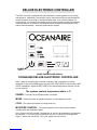
OCEANAIRE DELUXE ELECTRONIC CONTROLLER
When power is connected, the controller will display “888” momentarily, and then
disappear. Press the POWER button, then press the TEMP SELECT button until the SET
POINT is displayed. Adjust the SET POINT to the desired temperature, and the unit will
cool as required.
The systems controls temperature within +/- 2°
POWER—Turns the unit on/off when power is supplied
MODE - Selects the mode of operation between Cool and Moisture Control.
COOL - The system will operate in cooling mode only.
MOISTURE CONTROL - The system operates in the cooling mode to reduce
humidity within the conditioned space.
Every 4 hours, the fan is started, circulating the air, and the air temperature is recorded by
the controller. The cooling cycle is started for one hour, or until the room temperature
drops 2°, which ever comes first. This cycle repeats every four hours.
DELUXE ELECTRONIC CONTROLLER
The OWC controller is equipped with many features for a more precise level of cooling
and operation. Additionally, the controller can be removed from the unit and installed for
remote operation when using an extended display cable. Also, with the addition of a
remote sensor, the controller can operate away from the unit while sensing temperatures
in another space or in ductwork, overriding the inside temperature sensing bulb on the
bottom of the thermostat— accessory parts may be required.
POWER
button
INSIDE TEMPERATURE SENSOR

15
CONTROLLER PROGRAMMING MENU
1) Make sure the unit has power .
2) Press the power button “OFF”.
3) Press the following buttons in sequence “S-U-D-S”
(Select—Up arrow — Down arrow — Select)
4) The display will begin flashing P1 and a number.
If there is no display, repeat the sequence,
making sure the unit has power, but is turned OFF.
5) To adjust any program feature, press the ARROW UP▲ or ARROW DOWN ▼ button
until the desired value is displayed.
6) Use the “MODE” button to scroll through the programmable settings P1 through P16.
7) If no buttons are pressed, the display will then return to the “OFF” position after about
50 seconds.
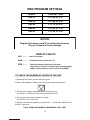
PROGRAM SETTINGS
P1—High Fan Speed Limit Setting. 56 - 85
P2—Low Fan Speed Limit Setting, 30 - 55
P4—Temperature Sensor Calibration, +/- 10°
P10— Temperature Display, °F or °C
P13—Supply Fan Operation, Cycling or Continuous
P15—Fan Motor Type Setting, PSC or Shaded Pole
P1, P2 - To adjust fan speed settings, P1 represents the high fan speed parameter, while
P2 represents the low fan speed parameter. When using nozzle kits, discharge duct
adapters and evaporator plenums, setting P1 to 85 will help to avoid freeze ups.
P4 - Adjust the P4 setting to match the actual INSIDE room temperature, if needed.
P10 - Use this parameter to display temperatures in the desired units.
P13 - To cycle the evaporator fan with the compressor, access code P-13. Press the up
or down button to switch to “CYC”, which means cycle the fan with the compressor. The
factory default setting is “CON”, which means continuous fan operation.
P15 - Fan Motors are PSC type, SC - should be selected.
8) Press POWER — you should see an alphanumeric code.
Press POWER and the unit will start at the new settings
FAN SPEED—The operator can select between AUTO or MANUAL fan speed control.
Pressing the FAN SPEED button will switch speed from AUTO to MANUAL. In MANUAL
mode, pressing the FAN SPEED button will change fan speed from low to high. In AUTO
mode, the fan speed is controlled automatically. In cooling mode, the controller
automatically adjusts the fan speed to high, and as the inside temperature approaches
the set point, the fan speed will decrease.
TEMP SELECT— Allows the operator to view the controller temperatures
INSIDE = return air temperature, DISCHARGE = supply air temperature,
SET POINT can be seen and adjusted, by pressing ▲ or▼.

MODEL CODE SETTINGS
OWC12 P1 = 85, P2 = 35
OWC18 P1 = 80, P2 = 50
OWC24 P1 = 70, P2 = 50
OWC36 P1 = 85, P2 = 40
OWC60 P1 = 85, P2 = 45
OWC PROGRAM SETTINGS
16
NOTICE
Program Parameters are NOT controller default values.
They are OceanAire Factory Settings
DISPLAY FAULTS
LAC……… Low AC line power
AAA……… Failed Air Sensor (unit will not run)
CON……… Failed Condensate Pump/Over-Flow Alarm
High Pressure Cut-Out—Low/interrupted condenser water
supply. Correct problem, and re-set unit at HP RESET
TO CHECK THE NUMBER OF HOURS ON THE UNIT
1) Disconnect unit power, and reconnect unit power.
2) When “888” appears in display, push and release the arrow down button
3) The first set of numbers displayed reads thousands of hours:
02 = 2000, 04 = 4000 hours, 00 means less than 1000 hours.
4) The second set of numbers read hours directly:
58 = 58 hours. 742 = 742 hours.
6) Add the 2 number sets together to get total hours. 03 and 486 = 3486 hours. 01
and 59 = 1059 hours.
TOTAL HOURS REPRESENTS COMPRESSOR “RUN” TIME

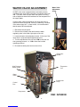
WATER VALVE ADJUSTMENT
All OWC units come equipped with an automatic pressure
regulated water valve which controls the condenser water flow
rate. The water valve will open when the system is running,
and will adjust the water flow rate based on the temperature of
the supply water.
In some cases, water temperatures can cause the valve to
open and close at a high rate, causing a “chattering” condition
in the water supply line. In these cases, it is recommended
that the water valve be adjusted.
1. Disconnect the unit power.
2. Remove the unit back panel and locate the water
regulating valve in the lower right region of the unit.
3. Locate the water valve adjustment screw. At the top of the
valve there is a square-shaped adjustment screw.
4. Turn the adjustment screw 1/4 turn CCW to raise the low
side operating pressure...or...CW to lower the low side
operating pressure.
5. Re-install the back panel and turn the unit on.
17
Water Valve
Adjustment
Screw
Evaporator
Blower
Evaporator
Coil
Condensate
Pump
Control
Box
Water
Valver
High Pressure
Reset Switch
Compressor
OWC INTERIOR

18
REPLACEMENT PARTS PROCEDURE
IT IS RECOMMENDED THAT ALL OCEANAIRE UNITS
BE SERVICED BY A LICENSED TECHNICIAN
WARNING—TO AVOID INJURY, DISCONNECT UNIT POWER
PRIOR TO SERVICING
A. FAN MOTOR
1. Remove cabinet left-side panel (when looking at the front of the unit).
2. Evaporator fan motor—disconnect evaporator motor wires from evaporator fan
contactor and power module.
3. For all model sizes 12, 18, 24, and 36, remove the screws securing motor and
inlet-ring to blower housing (all screws are external and visible), and remove blower
wheel-motor assembly. Remove the blower wheel set screw and disassemble the blower
wheel from the motor shaft and remove the motor.
For model size 60—loosen blower wheel shaft set screw, and remove the screws
securing the motor mount to the blower housing and remove motor and mount. Remove
the motor from the motor mount.
4. Install the new motor, reversing the removal procedure.
B. ELECTRONIC CONTROLLER (THERMOSTAT)
To remove the cooling only display, remove the cabinet left-side panel (from front).
Locate the two nuts securing the display to the front panel. Unplug the display cable
and remove display. Install new display and secure. Plug in display cable.
C. POWER MODULE
To remove the power module, remove the rear control box cover. Disconnect wires
(one at a time), and re-attach each wire, while holding replacement module in other hand.
Once all wires have been reconnected in accordance with the wiring diagram, install new
power module.
D. CONDENSATE PUMP
1. Remove left side panel.
2. Remove brackets securing condensate pump in base pan.
3. Disconnect pump wire leads at Molex connectors. Remove retainer clamp and tubing.
4. Replace pump, install by reversing procedure.
E. HIGH PRESSURE SAFETY SWITCH
1. Remove cabinet right side panel, or right rear side panel of Model 60.
2. Remove flare nut that secures capillary to the refrigeration system high pressure side.
A schrader valve is located in the discharge port which allows removal without losing
the refrigerant charge.
3. Remove two screws that secure high pressure switch.
4. Disconnect wire leads from compressor contactor and condensate pump safety switch.
5. Install new High Pressure Control, reversing the procedure.
To gain access to compressor and compressor run capacitor, remove left hand side
panel.
Page is loading ...
Page is loading ...
Page is loading ...
Page is loading ...
Page is loading ...
Page is loading ...
Page is loading ...
Page is loading ...
Page is loading ...
Page is loading ...
Page is loading ...
Page is loading ...
-
 1
1
-
 2
2
-
 3
3
-
 4
4
-
 5
5
-
 6
6
-
 7
7
-
 8
8
-
 9
9
-
 10
10
-
 11
11
-
 12
12
-
 13
13
-
 14
14
-
 15
15
-
 16
16
-
 17
17
-
 18
18
-
 19
19
-
 20
20
-
 21
21
-
 22
22
-
 23
23
-
 24
24
-
 25
25
-
 26
26
-
 27
27
-
 28
28
-
 29
29
-
 30
30
-
 31
31
-
 32
32


Ocean Aire OWC6012 Engineering, Installation And Service Manual
- Category
- Split-system air conditioners
- Type
- Engineering, Installation And Service Manual
- This manual is also suitable for
Ask a question and I''ll find the answer in the document
Finding information in a document is now easier with AI

Other documents
-
OceanAire OWC1811 Owner's manual
-
OceanAire PAC6012 Installation guide
-
-
SsangYong 1999 Musso User manual
-
OWC Jupiter Kore User guide
-
-
OceanAire CAC1211 Owner's manual
-
-
-