www.d.comChapter 1 Introduction
15
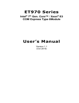
Signal Pin# Module Pin Type Pwr Rail / Tolerance WL968 Carrier Board Description
AC/HDA_RST# A30 O CMOS 3.3V Suspend/3.3V Connect to CODEC pin 11 RESET# Reset output to CODEC, active low.
AC/HDA_SYNC A29 O CMOS 3.3V/3.3V Connect to CODEC pin 10 SYNC Sample-synchronization signal to the CODEC(s).
AC/HDA_BITCLK A32 I/O CMOS 3.3V/3.3V Connect to CODEC pin 6 BIT_CLK Serial data clock generated by the external CODEC(s).
AC/HDA_SDOUT A33 O CMOS 3.3V/3.3V Connect to CODEC pin 5 SDATA_OUT Serial TDM data output to the CODEC.
AC/HDA_SDIN2 B28 I/O CMOS 3.3V Suspend/3.3V NA
AC/HDA_SDIN1 B29 I/O CMOS 3.3V Suspend/3.3V
AC/HDA_SDIN0 B30 I/O CMOS 3.3V Suspend/3.3V Connect 33 Ω in series to CODEC0 pin 8 SDATA_IN
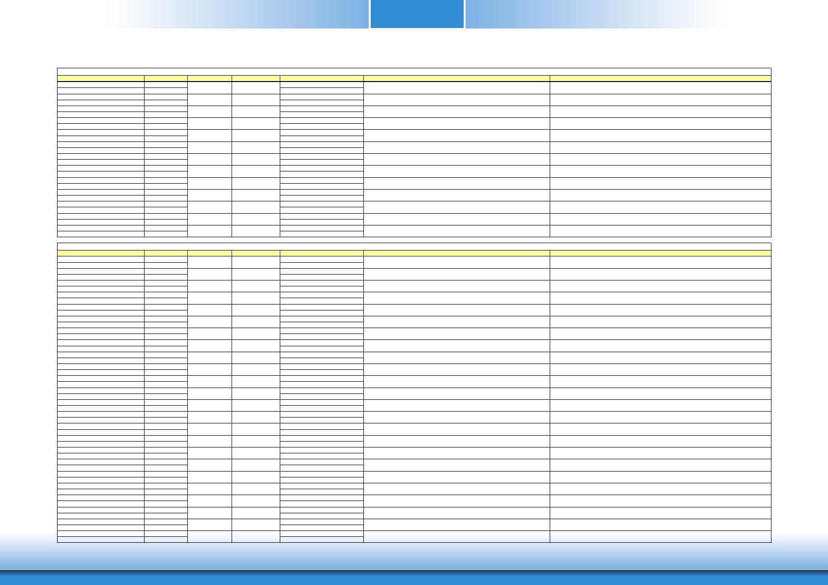
Signal Pin# Module Pin Type Pwr Rail / Tolerance WL968 Carrier Board Description
GBE0_MDI0+ A13 I/O Analog 3.3V max Suspend Connect to Magnetics Module MDI0+/-
Gigabit Ethernet Controller 0: Media Dependent Interface Differential
Pairs 0,1,2,3. The MDI can operate in 1000, 100 and 10 Mbit / sec
modes. Some pairs are unused in some modes, per the following:
1000BASE-T 100BASE-TX 10BASE-T
MDI[0]+/- B1_DA+/- TX+/- TX+/-
MDI[1]+/- B1_DB+/- RX+/- RX+/-
MDI[2]+/- B1_DC+/-
MDI[3]+/- B1_DD+/-
GBE0_MDI0- A12 I/O Analog 3.3V max Suspend
GBE0_MDI1+ A10 I/O Analog 3.3V max Suspend Connect to Magnetics Module MDI1+/-
GBE0_MDI1- A9 I/O Analog 3.3V max Suspend
GBE0_MDI2+ A7 I/O Analog 3.3V max Suspend Connect to Magnetics Module MDI2+/-
GBE0_MDI2- A6 I/O Analog 3.3V max Suspend
GBE0_MDI3+ A3 I/O Analog 3.3V max Suspend Connect to Magnetics Module MDI3+/-
GBE0_MDI3- A2 I/O Analog 3.3V max Suspend
GBE0_ACT# B2 OD CMOS 3.3V Suspend/3.3V Connect to LED and recommend current limit resistor 150Ω to 3.3VSB Gigabit Ethernet Controller 0 activity indicator, active low.
GBE0_LINK# A8 OD CMOS 3.3V Suspend/3.3V NC Gigabit Ethernet Controller 0 link indicator, active low.
GBE0_LINK100# A4 OD CMOS 3.3V Suspend/3.3V Connect to LED and recommend current limit resistor 150Ω to 3.3VSB Gigabit Ethernet Controller 0 100 Mbit / sec link indicator, active low.
GBE0_LINK1000# A5 OD CMOS 3.3V Suspend/3.3V Connect to LED and recommend current limit resistor 150Ω to 3.3VSB Gigabit Ethernet Controller 0 1000 Mbit / sec link indicator, active low.
Signal Pin# Module Pin Type Pwr Rail / Tolerance WL968 Carrier Board Description
SATA0_TX+ A16 O SATA AC coupled on Module AC Coupling capacitor
SATA0_TX- A17 O SATA AC coupled on Module AC Coupling capacitor
SATA0_RX+ A19 I SATA AC coupled on Module AC Coupling capacitor
SATA0_RX- A20 I SATA AC coupled on Module AC Coupling capacitor
SATA1_TX+ B16 O SATA AC coupled on Module AC Coupling capacitor
SATA1_TX- B17 O SATA AC coupled on Module AC Coupling capacitor
SATA1_RX+ B19 I SATA AC coupled on Module AC Coupling capacitor
SATA1_RX- B20 I SATA AC coupled on Module AC Coupling capacitor
SATA2_TX+ A22 O SATA AC coupled on Module NA
SATA2_TX- A23 O SATA AC coupled on Module NA
SATA2_RX+ A25 I SATA AC coupled on Module NA
SATA2_RX- A26 I SATA AC coupled on Module NA
SATA3_TX+ B22 O SATA AC coupled on Module NA
SATA3_TX- B23 O SATA AC coupled on Module NA
SATA3_RX+ B25 I SATA AC coupled on Module NA
SATA3_RX- B26 I SATA AC coupled on Module NA
(S)ATA_ACT# A28 I/O CMOS 3.3V / 3.3V PU 10K to 3.3V Connect to LED and recommend current limit resistor 220Ω to 3.3V ATA (parallel and serial) or SAS activity indicator, active low.
Signal Pin# Module Pin Type Pwr Rail / Tolerance WL968 Carrier Board Description
PCIE_TX0+ A68 AC Coupling capacitor
PCIE_TX0- A69 AC Coupling capacitor
PCIE_RX0+ B68
PCIE_RX0- B69
PCIE_TX1+ A64 AC Coupling capacitor
PCIE_TX1- A65 AC Coupling capacitor
PCIE_RX1+ B64
PCIE_RX1- B65
PCIE_TX2+ A61 AC Coupling capacitor
PCIE_TX2- A62 AC Coupling capacitor
PCIE_RX2+ B61
PCIE_RX2- B62
PCIE_TX3+ A58 AC Coupling capacitor
PCIE_TX3- A59 AC Coupling capacitor
PCIE_RX3+ B58
PCIE_RX3- B59
PCIE_TX4+ A55 AC Coupling capacitor
PCIE_TX4- A56 AC Coupling capacitor
PCIE_RX4+ B55
PCIE_RX4- B56
PCIE_TX5+ A52 AC Coupling capacitor
PCIE_TX5- A53 AC Coupling capacitor
PCIE_RX5+ B52
PCIE_RX5- B53
PCIE_TX6+ D19 AC Coupling capacitor
PCIE_TX6- D20 AC Coupling capacitor
PCIE_RX6+ C19
PCIE_RX6- C20
PCIE_TX7+ D22 NA
NA
NA NA
PCIE_RX7+ C22
PCIE_RX7- C23
PCIE0_CLK_REF+ A88
PCIE0_CLK_REF- A89
Signal Pin# Module Pin Type Pwr Rail / Tolerance
WL968
Carrier Board Description
PEG_TX0+ D52 NA
PEG_TX0- D53 NA
PEG_RX0+ C52 NA
PEG_RX0- C53 NA
PEG_TX1+ D55 NA
PEG_TX1- D56 NA
PEG_RX1+ C55 NA
PEG_RX1- C56 NA
PEG_TX2+ D58 NA
PEG_TX2- D59 NA
PEG_RX2+ C58 NA
PEG_RX2- C59 NA
PEG_TX3+ D61 NA
PEG_TX3- D62 NA
PEG_RX3+ C61
NA
PEG_RX3- C62 NA
PEG_TX4+ D65 NA
PEG_TX4- D66 NA
PEG_RX4+ C65 NA
PEG_RX4- C66 NA
PEG_TX5+ D68 NA
PEG_TX5- D69 NA
PEG_RX5+ C68 NA
PEG_RX5- C69 NA
PEG_TX6+ D71 NA
PEG_TX6- D72 NA
PEG_RX6+ C71 NA
PEG_RX6- C72
NA
PEG_TX7+ D74 NA
PEG_TX7- D75 NA
PEG_RX7+ C74 NA
PEG_RX7- C75 NA
PEG_TX8+ D78 NA
PEG_TX8- D79 NA
PEG_RX8+ C78 NA
PEG_RX8- C79 NA
PEG_TX9+ D81 NA
PEG_TX9- D82 NA
PEG_RX9+ C81 NA
PEG_RX9- C82 NA
PEG_TX10+ D85 NA
PEG_TX10- D86 NA
PEG_RX10+ C85 NA
PEG_RX10- C86 NA
PEG_TX11+ D88 NA
PEG_TX11- D89 NA
PEG_RX11+ C88 NA
PEG_RX11- C89 NA
PEG_TX12+ D91 NA
PEG_TX12- D92 NA
PEG_RX12+ C91 NA
PEG_RX12- C92 NA
PEG_TX13+ D94 NA
PEG_TX13- D95 NA
PEG_RX13+ C94 NA
PEG_RX13- C95 NA
PEG_TX14+ D98 NA
PEG_TX14- D99 NA
PEG_RX14+ C98 NA
PEG_RX14- C99 NA
PEG_TX15+ D101 NA
PEG_TX15- D102 NA
PEG_RX15+ C101 NA
PEG_RX15- C102 NA
PEG_LANE_RV# D54 I CMOS 3.3V / 3.3V PU 10K to 3.3V
PCI Express Graphics lane reversal input strap. Pull low on the Carrier
board to reverse lane order.
Signal Pin# Module Pin Type Pwr Rail / Tolerance
WL968
Carrier Board Description
DDI1_PAIR0+/SDVO1_RED+ D26 Connect AC Coupling Capacitors 0.1uF to Device
DDI1_PAIR0-
SDVO1_RED- D27 Connect AC Cou
acitors 0.1uF to Device
DDI1_PAIR1+/SDVO1_GRN+ D29 Connect AC Coupling Capacitors 0.1uF to Device
DDI1_PAIR1-/SDVO1_GRN- D30 Connect AC Coupling Capacitors 0.1uF to Device
DDI1_PAIR2+/SDVO1_BLU+ D32 Connect AC Coupling Capacitors 0.1uF to Device
DDI1_PAIR2-/SDVO1_BLU- D33 Connect AC Coupling Capacitors 0.1uF to Device
DDI1_PAIR3+/SDVO1_CK+ D36 Connect AC Coupling Capacitors 0.1uF to Device
DDI1_PAIR3-/SDVO1_CK- D37 Connect AC Coupling Capacitors 0.1uF to Device
DDI1_PAIR4+
DDI1_PAIR4-/SDVO1_INT- C26 NA
DDI1_PAIR5+/SDVO1_TVCLKIN+ C29 NA
DDI1_PAIR5-/SDVO1_TVCLKIN- C30 NA
DDI1_PAIR6+/SDVO1_FLDSTALL+ C15 NA
DDI1_PAIR6-/SDVO1_FLDSTALL- C16 NA
I/O PCIE AC coupled on Module
PD 100K to GND
(S/W IC between Rpu/PCH)
Connect to DP AUX+ DP AUX+ function if DDI1_DDC_AUX_SEL is no connect
I/O OD CMOS 3.3V / 3.3V
PU 4.7K to 3.3V, PD 100K to GND
(S/W IC between Rpu/Rpd
resistor)
Connect to HDMI/DVI I2C CTRLCLK HDMI/DVI I2C CTRLCLK if DDI1_DDC_AUX_SEL is pulled high
I/O PCIE AC coupled on Module
PU 100K to 3.3V
(S/W IC between Rpu/PCH)
Connect to DP AUX- DP AUX- function if DDI1_DDC_AUX_SEL is no connect
I/O OD CMOS 3.3V / 3.3V
PU 4.7K to 3.3V/PU 100K to 3.3V
(S/W IC between 4.7K/100K
resistor)
Connect to HDMI/DVI I2C CTRLDATA HDMI/DVI I2C CTRLDATA if DDI1_DDC_AUX_SEL is pulled high
DDI1_HPD C24 I CMOS 3.3V / 3.3V PD 1M and Connect to device Hot Plug Detect DDI Hot-Plug Detect
DDI1_DDC_AUX_SEL D34 I CMOS 3.3V / 3.3V PD 1M to GND PU 100K to 3.3V for DDC(HDMI/DVI)
Selects the function of DDI1_CTRLCLK_AUX+ and DDI1_CTRLDATA_AUX-.
DDI[n]_DDC_AUX_SEL shall be pulled to 3.3V on the Carrier with a 100K Ohm
resistor to configure the DDI[n]_AUX pair as the DDC channel.
Carrier DDI[n]_DDC_AUX_SEL should be connected to pin 13 of the DisplayPort
DDI2_PAIR0+ D39 Connect AC Coupling Capacitors 0.1uF to Device
DDI2_PAIR0- D40 Connect AC Coupling Capacitors 0.1uF to Device
DDI2_PAIR1+ D42 Connect AC Coupling Capacitors 0.1uF to Device
DDI2_PAIR1- D43 Connect AC Coupling Capacitors 0.1uF to Device
DDI2_PAIR2+ D46 Connect AC Coupling Capacitors 0.1uF to Device
DDI2_PAIR2- D47 Connect AC Coupling Capacitors 0.1uF to Device
DDI2_PAIR3+ D49 Connect AC Coupling Capacitors 0.1uF to Device
DDI2_PAIR3- D50 Connect AC Coupling Capacitors 0.1uF to Device
I/O PCIE AC coupled on Module
PD 100K to GND
(S/W IC between Rpu/PCH)
Connect to DP AUX+ DP AUX+ function if DDI2_DDC_AUX_SEL is no connect
I/O OD CMOS 3.3V / 3.3V
PU 4.7K to 3.3V, PD 100K to GND
(S/W IC between Rpu/Rpd
resistor)
Connect to HDMI/DVI I2C CTRLCLK HDMI/DVI I2C CTRLCLK if DDI2_DDC_AUX_SEL is pulled high
I/O PCIE AC coupled on Module
PU 100K to 3.3V
(S/W IC between Rpu/PCH)
Connect to DP AUX- DP AUX- function if DDI2_DDC_AUX_SEL is no connect
I/O OD CMOS 3.3V / 3.3V
PU 4.7K to 3.3V/PU 100K to 3.3V
(S/W IC between 4.7K/100K
resistor)
Connect to HDMI/DVI I2C CTRLDATA HDMI/DVI I2C CTRLDATA if DDI2_DDC_AUX_SEL is pulled high
DDI2_HPD D44 I CMOS 3.3V / 3.3V PD 1M and Connect to device Hot Plug Detect DDI Hot-Plug Detect
DDI2_DDC_AUX_SEL C34 I CMOS 3.3V / 3.3V PD 1M to GND PU 100K to 3.3V for DDC(HDMI/DVI)
Selects the function of DDI2_CTRLCLK_AUX+ and DDI2_CTRLDATA_AUX-.
DDI[n]_DDC_AUX_SEL shall be pulled to 3.3V on the Carrier with a 100K Ohm
resistor to configure the DDI[n]_AUX pair as the DDC channel.
Carrier DDI[n]_DDC_AUX_SEL should be connected to pin 13 of the DisplayPort
DDI3_PAIR0+ C39 NA
DDI3_PAIR0- C40 NA
DDI3_PAIR1+ C42 NA
DDI3_PAIR1- C43 NA
DDI3_PAIR2+ C46 NA
DDI3_PAIR2- C47 NA
DDI3_PAIR3+ C49 NA
DDI3_PAIR3- C50 NA
I/O PCIE AC coupled on Module NA DP AUX+ function if DDI3_DDC_AUX_SEL is no connect
I/O OD CMOS 3.3V / 3.3V NA HDMI/DVI I2C CTRLCLK if DDI3_DDC_AUX_SEL is pulled high
I/O PCIE AC coupled on Module NA DP AUX- function if DDI3_DDC_AUX_SEL is no connect
I/O OD CMOS 3.3V / 3.3V NA HDMI/DVI I2C CTRLDATA if DDI3_DDC_AUX_SEL is pulled high
DDI3_HPD C44 I CMOS 3.3V / 3.3V NA DDI Hot-Plug Detect
DDI3_DDC_AUX_SEL C38 I CMOS 3.3V / 3.3V NA
Selects the function of DDI3_CTRLCLK_AUX+ and DDI3_CTRLDATA_AUX-.
DDI[n]_DDC_AUX_SEL shall be pulled to 3.3V on the Carrier with a 100K Ohm
resistor to configure the DDI[n]_AUX pair as the DDC channel.
Carrier DDI[n]_DDC_AUX_SEL should be connected to pin 13 of the DisplayPort
Signal Pin# Module Pin Type Pwr Rail / Tolerance WL968 Carrier Board Description
USB0+ A46
USB0- A45
USB1+ B46
USB1- B45
USB2+ A43
USB2- A42
USB3+ B43
USB3- B42
USB4+ A40
USB4- A39
USB5+ B40
USB5- B39
USB6+ A37
USB6- A36
USB7+ B37
USB7- B36
USB_0_1_OC# B44 I CMOS 3.3V Suspend/3.3V PU 10k to 3V3_DU Connect to Overcurrent of USB Power Switch
USB over-current sense, USB channels 0 and 1. A pull-up for this line
shall be present on the Module. An open drain driver from a USB
current monitor on the Carrier Board may drive this line low. Do not
pull this line high on the Carrier Board.
USB_2_3_OC# A44 I CMOS 3.3V Suspend/3.3V PU 10k to 3V3_DU Connect to Overcurrent of USB Power Switch
USB over-current sense, USB channels 2 and 3. A pull-up for this line
shall be present on the Module. An open drain driver from a USB
current monitor on the Carrier Board may drive this line low. Do not
pull this line high on the Carrier Board.
USB_4_5_OC# B38 I CMOS 3.3V Suspend/3.3V PU 10k to 3V3_DU Connect to Overcurrent of USB Power Switch
USB over-current sense, USB channels 4 and 5. A pull-up for this line
shall be present on the Module. An open drain driver from a USB
current monitor on the Carrier Board may drive this line low. Do not
pull this line high on the Carrier Board.
USB_6_7_OC# A38 I CMOS 3.3V Suspend/3.3V PU 10k to 3V3_DU Connect to Overcurrent of USB Power Switch
USB over-current sense, USB channels 6 and 7. A pull-up for this line
shall be present on the Module. An open drain driver from a USB
current monitor on the Carrier Board may drive this line low. Do not
pull this line high on the Carrier Board.
USB_SSTX0+ D4 AC Coupling capacitor
USB_SSTX0- D3 AC Coupling capacitor
USB_SSRX0+ C4
USB_SSRX0- C3
USB_SSTX1+ D7 AC Coupling capacitor
USB_SSTX1- D6 AC Coupling capacitor
USB_SSRX1+ C7
USB_SSRX1- C6
USB_SSTX2+ D10 AC Coupling capacitor
USB_SSTX2- D9 AC Coupling capacitor
USB_SSRX2+ C10
USB_SSRX2- C9
USB_SSTX3+ D13 AC Coupling capacitor
USB_SSTX3- D12 AC Coupling capacitor
USB_SSRX3+ C13
USB_SSRX3- C12
Signal Pin# Module Pin Type Pwr Rail / Tolerance
WL968
Carrier Board Description
LVDS_A0+ A71
LVDS_A0- A72
LVDS_A1+ A73
LVDS_A1- A74
LVDS_A2+ A75
LVDS_A2- A76
LVDS_A3+ A78
LVDS_A3- A79
LVDS_A_CK+ A81
LVDS_A_CK- A82
LVDS_B0+ B71
LVDS_B0- B72
LVDS_B1+ B73
LVDS_B1- B74
LVDS_B2+ B75
LVDS_B2- B76
LVDS_B3+ B77
LVDS_B3- B78
LVDS_B_CK+ B81
LVDS_B_CK- B82
LVDS_VDD_EN A77 O CMOS 3.3V / 3.3V Connect to enable control of LVDS panel power circuit LVDS panel power enable
LVDS_BKLT_EN B79 O CMOS 3.3V / 3.3V Connect to enable control of LVDS panel backlight power circuit. LVDS panel backlight enable
LVDS_BKLT_CTRL B83 O CMOS 3.3V / 3.3V Connect to brightness control of LVDS panel backlight power circuit. LVDS panel backlight brightness control
LVDS_I2C_CK A83 I/O OD CMOS 3.3V / 3.3V PU 4.7K to 3.3V Connect to DDC clock of LVDS panel I2C clock output for LVDS display use
LVDS_I2C_DAT A84 I/O OD CMOS 3.3V / 3.3V PU 4.7K to 3.3V Connect to DDC data of LVDS panel I2C data line for LVDS display use
Signal Pin# Module Pin Type Pwr Rail / Tolerance WL968 Carrier Board Description
LPC_AD0 B4
LPC_AD1 B5
LPC_AD2 B6
LPC_AD3 B7
LPC_FRAME# B3 O CMOS 3.3V / 3.3V LPC frame indicates the start of an LPC cycle
LPC_DRQ0# B8 PU 10K to 3.3V NC
LPC_DRQ1# B9 PU 10K to 3.3V NC
LPC_SERIRQ A50 I/O CMOS 3.3V / 3.3V PU 10K to 3.3V LPC serial interrupt
LPC_CLK B10 O CMOS 3.3V / 3.3V LPC clock output - 24MHz nominal
Signal Pin# Module Pin Type Pwr Rail / Tolerance WL968 Carrier Board Description
SPI_CS# B97 O CMO
3.3V Connect to Carrier Board SPI Device CS#
select for Carrier Board SPI - ma
set SPI0 or SPI1
SPI_MISO A92 I CMOS 3.3V Suspend/3.3V Connect a series resistor 33Ω
to Carrier Board SPI Device SO pin Data in to Module from Carrier SPI
SPI_MOSI A95 O CMOS 3.3V Suspend/3.3V Connect a series resistor 33Ω
to Carrier Board SPI Device SI pin Data out from Module to Carrier SPI
SPI_CLK A94 O CMOS 3.3V Suspend/3.3V Connect a series resistor 33Ω
to Carrier Board SPI Device SCK pin Clock from Module to Carrier SPI
SPI_POWER A91 O 3.3V Suspend/3.3V
Power supply for Carrier Board SPI – sourced from Module – nominally
3.3V. The Module shall provide a minimum of 100mA on SPI_POWER.
Carriers shall use less than 100mA of SPI_POWER. SPI_POWER
shall only be used to power SPI devices on the Carrier Board.
BIOS_DIS0# A34
BIOS_DIS1# B88
Signal Pin# Module Pin Type Pwr Rail / Tolerance
WL968
Carrier Board Description
VGA_RED B89 O Analog Analog PD 150 to GND PD 150R,connect to VGA connector with EMI filter & ESD protect component. Red for monitor. Analog output
VGA_GRN B91 O Analog Analog PD 150 to GND PD 150R,connect to VGA connector with EMI filter & ESD protect component. Green for monitor. Analog output
VGA_BLU B92 O Analog Analog PD 150 to GND PD 150R,connect to VGA connector with EMI filter & ESD protect component. Blue for monitor. Analog output
VGA_HSYNC B93 O CMOS 3.3V / 3.3V Connect to VGA connector with a3.3V Buffer IC to isolate PCH & Display Device Horizontal sync output to VGA monitor
VGA_VSYNC B94 O CMOS 3.3V / 3.3V Connect to VGA connector with a 33V Buffer IC to isolate PCH & Display Device Vertical sync output to VGA monitor
VGA_I2C_CK B95 I/O OD CMOS 3.3V / 3.3V PU 2.2K to 3.3V Connect to VGA connector with a 3.3V to 5V Level shift circuit. DDC clock line (I2C port dedicated to identify VGA monitor capabilities)
VGA_I2C_DAT B96 I/O OD CMOS 3.3V / 3.3V PU 2.2K to 3.3V Connect to VGA connector with a 3.3V to 5V Level shift circuit. DDC data line.
Signal Pin# Module Pin Type Pwr Rail / Tolerance
WL968
Carrier Board Description
SER0_TX A98 O CMOS 3.3V/5V PD 4.7K to GND
General purpose serial port 0 transmitter
(Recommend add Protecting Logic Level Signals on Pins Reclaimed from VCC_12V)
SER0_RX A99 I CMOS 3.3V/5V PU 10K to 3.3V
General purpose serial port 0 receiver
(Recommend add Protecting Logic Level Signals on Pins Reclaimed from VCC_12V)
SER1_TX A101 O CMOS 3.3V/5V PD 4.7K to GND
General purpose serial port 1 transmitter
(Recommend add Protecting Logic Level Signals on Pins Reclaimed from VCC_12V)
SER1_RX A102 I CMOS 3.3V/5V PU 10K to 3.3V
General purpose serial port 1 receiver
(Recommend add Protecting Logic Level Signals on Pins Reclaimed from VCC_12V)
Signal Pin# Module Pin Type Pwr Rail / Tolerance
WL968
Carrier Board Description
I2C_CK B33 I/O OD CMOS 3.3V Suspend/3.3V PU 2.2K to 3V3_DU_EC General purpose I2C port clock output
I2C_DAT B34 I/O OD CMOS 3.3V Suspend/3.3V PU 2.2K to 3V3_DU_EC General purpose I2C port data I/O line
SPKR B32 O CMOS 3.3V / 3.3V
Output for audio enunciator - the "speaker" in PC-AT systems.
This port provides the PC beep signal and is mostly intended for
debugging purposes.
WDT B27 O CMOS 3.3V / 3.3V Output indicating that a watchdog time-out event has occurred.
FAN_PWMOUT B101 O OD CMOS 3.3V / 3.3V
Fan speed control. Uses the Pulse Width Modulation (PWM) technique to control the fan's RPM.
(Recommend add Protecting Logic Level Signals on Pins Reclaimed from VCC_12V)
FAN_TACHIN B102 I OD CMOS 3.3V / 3.3V PU 47K to 3V3
Fan tachometer input for a fan with a two pulse output.
(Recommend add Protecting Logic Level Signals on Pins Reclaimed from VCC_12V)
TPM_PP A96 I CMOS 3.3V / 3.3V Default NA, PD 4.7K when stuff TPM chip
Trusted Platform Module (TPM) Physical Presence pin. Active high.
TPM chip has an internal pull down. This signal is used to indicate
Physical Presence to the TPM.
Signal Pin# Module Pin Type Pwr Rail / Tolerance
WL968
Carrier Board Description
PWRBTN# B12 I CMOS 3.3V Suspend/3.3V PU 10K to 3V3_DU_EC PU 4.7K to 3V3_SB
A falling edge creates a power button event. Power button events can
be used to bring a system out of S5 soft off and other suspend states,
as well as powering the system down.
SYS_RESET# B49 I CMOS 3.3V Suspend/3.3V PU 10K to 3V3_DU NC PU 4.7K to 3V3_SB
Reset button input. Active low request for Module to reset and reboot.
May be falling edge sensitive. For situations when SYS_RESET# is
not able to reestablish control of the system, PWR_OK or a power
cycle may be used.
CB_RESET# B50 O CMOS 3.3V Suspend/3.3V PD 100K to GND
Reset output from Module to Carrier Board. Active low. Issued by
Module chipset and may result from a low SYS_RESET# input, a low
PWR_OK input, a VCC_12V power input that falls below the minimum
specification, a watchdog timeout, or may be initiated by the Module
software.
PWR_OK B24 I CMOS 3.3V / 3.3V
PU 10K to 5V and PD 20K
Power OK from main power supply. A high value indicates that the
power is good. This signal can be used to hold off Module startup to
allow Carrier based FPGAs or other configurable devices time to be
programmed.
SUS_STAT# B18 O CMOS 3.3V Suspend/3.3V Indicates imminent suspend operation; used to notify LPC devices.
SUS_S3# A15 O CMOS 3.3V Suspend/3.3V PD 10K to GND
Indicates system is in Suspend to RAM state. Active low output. An
inverted copy of SUS_S3# on the Carrier Board may be used to
enable the non-standby power on a typical ATX supply.
SUS_S4# A18 O CMOS 3.3V Suspend/3.3V
PD 10K to GND
Indicates system is in Suspend to Disk state. Active low output.
SUS_S5# A24 O CMOS 3.3V Suspend/3.3V PD 10K to GND Indicates system is in Soft Off state.
WAKE0# B66 I CMOS 3.3V Suspend/3.3V PU 1K to 3V3_DU PCI Express wake up signal.
WAKE1# B67 I CMOS 3.3V Suspend/3.3V PU 10K to 3V3_DU
General purpose wake up signal. May be used to implement wake-up
on PS2 keyboard or mouse activity.
BATLOW# A27 I CMOS 3.3V Suspend/ 3.3V PU 10K to 3V3_DU
Indicates that external battery is low.
This port provides a battery-low signal to the Module for orderly
transitioning to power saving or power cut-off ACPI modes.
LID# A103 I OD CMOS 3.3V Suspend/12V PU 47K to 3V3_DU_EC
LID switch. Low active signal used by the ACPI operating system for a LID switch.
(Recommend add Protecting Logic Level Signals on Pins Reclaimed from VCC_12V)
SLEEP# B103 I OD CMOS 3.3V Suspend/12V
PU 10K to 3V3_DU_EC
Sleep button. Low active signal used by the ACPI operating system to bring the
system to sleep state or to wake it up again.
(Recommend add Protecting Logic Level Signals on Pins Reclaimed from VCC_12V)
THRM# B35 I CMOS 3.3V / 3.3V
PU 10K to 3V3
Input from off-Module temp sensor indicating an over-temp situation.
THRMTRIP# A35 O CMOS 3.3V / 3.3V PU 10K to 3.3V Active low output indicating that the CPU has entered thermal shutdown.
SMB_CK B13 I/O OD CMOS 3.3V Suspend/3.3V PU 2.2K to 3V3_DU_EC System Management Bus bidirectional clock line.
SMB_DAT B14 I/O OD CMOS 3.3V Suspend/3.3V PU 2.2K to 3V3_DU_EC System Management Bus bidirectional data line.
SMB_ALERT# B15 I CMOS 3.3V Suspend/3.3V PU 2.2K to 3V3_DU_EC
System Management Bus Alert – active low input can be used to
generate an SMI# (System Management Interrupt) or to wake the system.
Signal Pin# Module Pin Type Pwr Rail / Tolerance
WL968
Carrier Board Description
GPO0 A93
GPO1 B54
GPO2 B57
GPO3 B63
GPI0 A54 PU 10K to 3.3V
GPI1 A63
PU 10K to 3.3V
GPI2 A67 PU 10K to 3.3V
GPI3 A85 PU 10K to 3.3V
Signal Pin# Module Pin Type Pwr Rail / Tolerance
WL968
Carrier Board Description
VCC_12V
104~A109
B104~B109
C104~C109
D104~D109
Power Primary power input: +12V nominal. All available VCC_12V pins on the connector(s) shall be used.
VCC_5V_SBY B84~B87 Power
Standby power input: +5.0V nominal. If VCC5_SBY is used, all
available VCC_5V_SBY pins on the connector(s) shall be used. Only
used for standby and suspend functions. May be left unconnected if
these functions are not used in the system design.
VCC_RTC A47 Power Real-time clock circuit-power input. Nominally +3.0V.
GND
A1, A11, A21, A31,
A41, A51, A57, A60,
A66, A70, A80, A90,
A100, A110, B1,
B11, B21 ,B31, B41,
B51, B60, B70, B80,
B90, B100, B110,
C1, C2, C5, C8, C11,
C14, C21, C31, C41,
C51, C60, C70, C73,
C76, C80, C84, C87,
C90, C93, C96,
C100, C103, C110,
D1, D2, D5, D8,
D11, D14, D21,
D31, D51, D60,
D67, D70, D73,
D76, D80, D84,
D87, D90, D93,
D96, D100, D103,
D110
Power
Ground - DC power and signal and AC signal return path.
All available GND connector pins shall be used and tied to Carrier
Board GND plane.
Connect to LPC device
Connect to LPC device
O PCIE AC coupled on Module
Connect 90� @100MHz Common Choke in series and ESD suppressors to GND to USB
connector
Additional transmit signal differential pairs for the SuperSpeed USB data path.
I PCIE AC coupled off Module
Connect 90� @100MHz Common Choke in series and ESD suppressors to GND to USB
connector
Additional receive signal differential pairs for the SuperSpeed USB data path.
O PCIE AC coupled on Module
Connect 90� @100MHz Common Choke in series and ESD suppressors to GND to USB
connector
Additional transmit signal differential pairs for the SuperSpeed USB data path.
I PCIE AC coupled off Module
Connect to PCIE device or slot
Device - Connect AC Coupling cap 0.1uF
Slot - Connect to PCIE Conn pin
Connect to PCIE device or slot
Device - Connect AC Coupling cap 0.1uF
Slot - Connect to PCIE Conn pin
Default NA(Request by BOM option)
Default NA(Request by BOM option)
Connect to PCIE device or slot
Device - Connect AC Coupling cap 0.1uF
Slot - Connect to PCIE Conn pin
Connect to PCIE device or slot
Device - Connect AC Coupling cap 0.1uF
Slot - Connect to PCIE Conn pin
Connect to PCIE device or slot
Pin Types
I Input to the Module
O Output from the Module
I/O Bi-directional input / output signal
OD Open drain output
AC coupled off Module Serial Digital Video Field Stall input differential pair.
O PCIE
O PCIE AC coupled off Module DDI 1 Pair 3 differential pairs/Serial Digital Video B clock output differential pair
I PCIE
I PCIE AC coupled off Module Serial Digital Video TVOUT synchronization clock input differential pair.
AC coupled off Module
Selection straps to determine the BIOS boot device.
The Carrier should only float these or pull them low, please refer to
below table for strapping options of BIOS disable signals.
LVDS Channel B differential clock
LPC Si
O PCIE AC coupled off Module
DDI 3 Pair 0 differential pairs
O PCIE AC coupled off Module DDI 2 Pair 3 differential pairs
DDI 3 Pair 2 differential pairs
O PCIE DDI 3 Pair 1 differential pairs
DDI3_CTRLCLK_AUX+ C36
DDI3_CTRLDATA_AUX- C37
O PCIE AC coupled off Module
DDI 2 Pair 0 differential pairs
O PCIE AC coupled off Module DDI 3 Pair 3 differential pairs
AC coupled off Module
DDI Si
O PCIE AC coupled off Module DDI 1 Pair 0 differential pairs/Serial Digital Video B red output differential pair
I PCIE
3.3V / 3.3V LPC serial DMA request
SPI Si
O PCIE AC coupled off Module DDI 2 Pair 2 differential pairs
O PCIE AC coupled off Module DDI 2 Pair 1 differential pairs
O PCIE AC coupled off Module
DDI2_CTRLCLK_AUX+ C32
DDI2_CTRLDATA_AUX- C33
DDI1_CTRLCLK_AUX+/SDVO1_CTRLCLK D15
DDI1_CTRLDATA_AUX-
/SDVO1_CTRLDATA
D16
AC coupled off Module DDI 1 Pair 2 differential pairs/Serial Digital Video B blue output differential pair
O PCIE AC coupled off Module DDI 1 Pair 1 differential pairs/Serial Digital Video B green output differential pair
Power and GND Si
O LVDS LVDS
Connect to LVDS connector
O LVDS LVDS
Connect to LVDS connector
I/O CMOS 3.3V / 3.3V
I CMOS 3.3V / 3.3V
General purpose input pins.
Pulled high internally on the Module.
Power and S
O CMOS
Serial Digital Video B interrupt input differential pair.
General purpose output pins.
Upon a hardware reset, these outputs should be low.
NA
3.3V / 3.3V
O LVDS LVDS
LVDS
Connect to LVDS connector
O LVDS LVDS
LPC multiplexed address, command and data bus
O LVDS LVDS
Connect to LVDS connector
LVDS Channel B differential pairs
Ther LVDS flat panel differential pairs (LVDS_A[0:3]+/-, LVDS_B[0:3]+/-. LVDS_A_CK+/-,
LVDS_B_CK+/-) shall have 100Ω terminations across the pairs at the destination. These
terminations may be on the Carrier Board if the Carrier Board implements a LVDS deserializer
on-board
O LVDS LVDS
Connect to LVDS connector
Connect to LVDS connector
LVDS Channel A differential clockO LVDS LVDS
Connect to LVDS connector
Serial Interface Si
I CMOS
I CMOS
I/O USB 3.3V Suspend/3.3V
Connect 90� @100MHz Common Choke in series and ESD suppressors to GND to USB
connector
USB differential pairs 7
LVDS Si
O LVDS LVDS
Connect to LVDS connector LVDS Channel A differential pairs
Ther LVDS flat panel differential pairs (LVDS_A[0:3]+/-, LVDS_B[0:3]+/-. LVDS_A_CK+/-,
LVDS_B_CK+/-) shall have 100Ω terminations across the pairs at the destination. These
terminations may be on the Carrier Board if the Carrier Board implements a LVDS deserializer
on-board
O LVDS
Connect to LVDS connector
O LVDS LVDS
Connect to LVDS connector
Connect 90� @100MHz Common Choke in series and ESD suppressors to GND to USB
connector
Additional receive signal differential pairs for the SuperSpeed USB data path.
O PCIE AC coupled on Module
Connect 90� @100MHz Common Choke in series and ESD suppressors to GND to USB
connector
Additional transmit signal differential pairs for the SuperSpeed USB data path.
I PCIE AC coupled off Module
Connect 90� @100MHz Common Choke in series and ESD suppressors to GND to USB
connector
Additional receive signal differential pairs for the SuperSpeed USB data path.
I/O USB
I/O USB 3.3V Suspend/3.3V
Connect 90� @100MHz Common Choke in series and ESD suppressors to GND to USB
connector
USB differential pairs 2
I/O USB 3.3V Suspend/3.3V
Connect 90� @100MHz Common Choke in series and ESD suppressors to GND to USB
connector
USB differential pairs 1
I/O USB 3.3V Suspend/3.3V
Connect 90� @100MHz Common Choke in series and ESD suppressors to GND to USB
connector
USB differential pairs 6
3.3V Suspend/3.3V
Connect 90� @100MHz Common Choke in series and ESD suppressors to GND to USB
connector
USB differential pairs 4
I/O USB 3.3V Suspend/3.3V
Connect 90� @100MHz Common Choke in series and ESD suppressors to GND to USB
connector
USB differential pairs 3
I/O USB 3.3V Suspend/3.3V
Connect 90� @100MHz Common Choke in series and ESD suppressors to GND to USB
connector
USB differential pairs 5
USB Si
I/O USB 3.3V Suspend/3.3V
Connect 90� @100MHz Common Choke in series and ESD suppressors to GND to USB
connector
USB differential pairs 0
I PCIE AC coupled off Module
PCI Express Graphics receive differential pairs 14
PCI Express Graphics receive differential pairs 12
O PCIE AC coupled on Module PCI Express Graphics transmit differential pairs 14
I PCIE AC coupled off Module PCI Express Graphics receive differential pairs 15
I PCIE AC coupled off Module PCI Express Graphics receive differential pairs 13
O PCIE AC coupled on Module PCI Express Graphics transmit differential pairs 15
I PCIE AC coupled off Module
O PCIE AC coupled on Module PCI Express Graphics transmit differential pairs 13
O PCIE AC coupled on Module PCI Express Graphics transmit differential pairs 12
O PCIE AC coupled on Module PCI Express Graphics transmit differential pairs 11
I PCIE AC coupled off Module
I PCIE AC coupled off Module PCI Express Graphics receive differential pairs 11
PCI Express Graphics receive differential pairs 10
I PCIE AC coupled off Module PCI Express Graphics receive differential pairs 8
O PCIE AC coupled on Module PCI Express Graphics transmit differential pairs 10
I PCIE AC coupled off Module PCI Express Graphics receive differential pairs 9
O PCIE AC coupled on Module PCI Express Graphics transmit differential pairs 9
O PCIE AC coupled on Module PCI Express Graphics transmit differential pairs 8
I PCIE AC coupled off Module PCI Express Graphics receive differential pairs 5
O PCIE
O PCIE AC coupled on Module PCI Express Graphics transmit differential pairs 6
O PCIE AC coupled on Module PCI Express Graphics transmit differential pairs 5
I PCIE AC coupled off Module PCI Express Graphics receive differential pairs 7
AC coupled on Module PCI Express Graphics transmit differential pairs 7
I PCIE AC coupled off Module PCI Express Graphics receive differential pairs 6
PCI Express Graphics transmit differential pairs 4
I PCIE AC coupled off Module
I PCIE AC coupled off Module PCI Express Graphics receive differential pairs 3
I PCIE AC coupled off Module PCI Express Graphics receive differential pairs 2
O PCIE AC coupled on Module PCI Express Graphics transmit differential pairs 3
PCI Express Graphics receive differential pairs 4
O PCIE AC coupled on Module
O PCIE AC coupled on Module
I PCIE
PCI Express Graphics transmit differential pairs 2
PEG Si
O PCIE AC coupled on Module PCI Express Graphics transmit differential pairs 0
I PCIE AC coupled off Module PCI Express Graphics receive differential pairs 0
O PCIE AC coupled on Module PCI Express Graphics transmit differential pairs 1
AC coupled off Module PCI Express Graphics receive differential pairs 1
I PCIE AC coupled off Module
I PCIE AC coupled off Module
O PCIE AC coupled on Module
PCI Express Differential Receive Pairs 7
,ecived EICP ot tcennoCEICPEICP O PCIe CLK Buffer or slot
Reference clock output for all PCI Express and PCI Express Graphics
lanes.
PCI Express Differential Receive Pairs 6
O PCIE AC coupled on Module PCI Express Differential Transmit Pairs 7
PCI Express Differential Transmit Pairs 4
PCI Express Differential Receive Pairs 2
PCI Express Differential Transmit Pairs 6
PCI Express Differential Transmit Pairs 3
I PCIE AC coupled off Module PCI Express Differential Receive Pairs 5
I PCIE AC coupled off Module
O PCIE AC coupled on Module PCI Express Differential Transmit Pairs 5
I PCIE AC coupled off Module PCI Express Differential Receive Pairs 4
O PCIE AC coupled on Module
O PCIE AC coupled on Module
Device - Connect AC Coupling cap 0.1uF
Slot - Connect to PCIE Conn pin
Connect to PCIE device or slot
Device - Connect AC Coupling cap 0.1uF
Slot - Connect to PCIE Conn pin
Connect to PCIE device or slot
Device - Connect AC Coupling cap 0.1uF
Slot - Connect to PCIE Conn pin
AC coupled on Module PCI Express Differential Transmit Pairs 1
PCI Express Differential Receive Pairs 1
PCI Express Differential Receive Pairs 3
O PCIE AC coupled on Module PCI Express Differential Transmit Pairs 0
O PCIE AC coupled on Module PCI Express Differential Transmit Pairs 2
I PCIE AC coupled off Module
I PCIE AC coupled off Module PCI Express Differential Receive Pairs 0
I PCIE AC coupled off Module
O PCIE
Serial TDM data inputs from up to 2 CODECs.
Gi
PCI Ex
ress Lanes Si
nals Descri
tion
Serial ATA or SAS Channel 0 transmit differential pair.
Connect to SATA0 Conn RX pin Serial ATA or SAS Channel 0 receive differential pair.
Connect to SATA1 Conn TX pin
Default NA (Request by BOM option)
Serial ATA or SAS Channel 3 transmit differential pair.
Serial ATA or SAS Channel 3 receive differential pair.
Default NA (Request by BOM option)
Serial ATA or SAS Channel 2 receive differential pair.
Serial ATA or SAS Channel 2 transmit differential pair.
Connect to SATA1 Conn RX pin Serial ATA or SAS Channel 1 receive differential pair.
SATA Si
Connect to SATA0 Conn TX pin
Serial ATA or SAS Channel 1 transmit differential pair.
Ref
Line
Bios
Entry
SPI
Descriptor
Carrier
SPI_CS#
Chipset
SPI CS0#
Destination
Chipset
SPI CS1#
Destination
BIOS
DIS0#
BIOS
DIS1#
1
1
1
1
00
0
0
ModuleModule SPI0/SPI1
SPI1
(Default)
SPI0
High
High
CarrierCarrier
Carrier
(Default)
Module
(Default)
Module
Module
Module
(Default)
Module
ModuleModule
3
2
1
0
Carrier FWH
SPI0/SPI1
(Default)
SPI0/SPI1
DDI2 is option function
Signal Pin# Module Pin Type Pwr Rail / Tolerance WL968 Carrier Board Description
AC/HDA_RST# A30 O CMOS 3.3V Suspend/3.3V Connect to CODEC pin 11 RESET# Reset output to CODEC, active low.
AC/HDA_SYNC A29 O CMOS 3.3V/3.3V Connect to CODEC pin 10 SYNC Sample-synchronization signal to the CODEC(s).
AC/HDA_BITCLK A32 I/O CMOS 3.3V/3.3V Connect to CODEC pin 6 BIT_CLK Serial data clock generated by the external CODEC(s).
AC/HDA_SDOUT A33 O CMOS 3.3V/3.3V Connect to CODEC pin 5 SDATA_OUT Serial TDM data output to the CODEC.
AC/HDA_SDIN2 B28 I/O CMOS 3.3V Suspend/3.3V NA
AC/HDA_SDIN1 B29 I/O CMOS 3.3V Suspend/3.3V
AC/HDA_SDIN0 B30 I/O CMOS 3.3V Suspend/3.3V Connect 33 Ω in series to CODEC0 pin 8 SDATA_IN
Signal Pin# Module Pin Type Pwr Rail / Tolerance WL968 Carrier Board Description
GBE0_MDI0+ A13 I/O Analog 3.3V max Suspend Connect to Magnetics Module MDI0+/-
Gigabit Ethernet Controller 0: Media Dependent Interface Differential
Pairs 0,1,2,3. The MDI can operate in 1000, 100 and 10 Mbit / sec
modes. Some pairs are unused in some modes, per the following:
1000BASE-T 100BASE-TX 10BASE-T
MDI[0]+/- B1_DA+/- TX+/- TX+/-
MDI[1]+/- B1_DB+/- RX+/- RX+/-
MDI[2]+/- B1_DC+/-
MDI[3]+/- B1_DD+/-
GBE0_MDI0- A12 I/O Analog 3.3V max Suspend
GBE0_MDI1+ A10 I/O Analog 3.3V max Suspend Connect to Magnetics Module MDI1+/-
GBE0_MDI1- A9 I/O Analog 3.3V max Suspend
GBE0_MDI2+ A7 I/O Analog 3.3V max Suspend Connect to Magnetics Module MDI2+/-
GBE0_MDI2- A6 I/O Analog 3.3V max Suspend
GBE0_MDI3+ A3 I/O Analog 3.3V max Suspend Connect to Magnetics Module MDI3+/-
GBE0_MDI3- A2 I/O Analog 3.3V max Suspend
GBE0_ACT# B2 OD CMOS 3.3V Suspend/3.3V Connect to LED and recommend current limit resistor 150Ω to 3.3VSB Gigabit Ethernet Controller 0 activity indicator, active low.
GBE0_LINK# A8 OD CMOS 3.3V Suspend/3.3V NC Gigabit Ethernet Controller 0 link indicator, active low.
GBE0_LINK100# A4 OD CMOS 3.3V Suspend/3.3V Connect to LED and recommend current limit resistor 150Ω to 3.3VSB Gigabit Ethernet Controller 0 100 Mbit / sec link indicator, active low.
GBE0_LINK1000# A5 OD CMOS 3.3V Suspend/3.3V Connect to LED and recommend current limit resistor 150 Ω to 3.3VSB Gigabit Ethernet Controller 0 1000 Mbit / sec link indicator, active low.
Signal Pin# Module Pin Type Pwr Rail / Tolerance WL968 Carrier Board Description
SATA0_TX+ A16 O SATA AC coupled on Module AC Coupling capacitor
SATA0_TX- A17 O SATA AC coupled on Module AC Coupling capacitor
SATA0_RX+ A19 I SATA AC coupled on Module AC Coupling capacitor
SATA0_RX- A20 I SATA AC coupled on Module AC Coupling capacitor
SATA1_TX+ B16 O SATA AC coupled on Module AC Coupling capacitor
SATA1_TX- B17 O SATA AC coupled on Module AC Coupling capacitor
SATA1_RX+ B19 I SATA AC coupled on Module AC Coupling capacitor
SATA1_RX- B20 I SATA AC coupled on Module AC Coupling capacitor
SATA2_TX+ A22 O SATA AC coupled on Module NA
SATA2_TX- A23 O SATA AC coupled on Module NA
SATA2_RX+ A25 I SATA AC coupled on Module NA
SATA2_RX- A26 I SATA AC coupled on Module NA
SATA3_TX+ B22 O SATA AC coupled on Module NA
SATA3_TX- B23 O SATA AC coupled on Module NA
SATA3_RX+ B25 I SATA AC coupled on Module NA
SATA3_RX- B26 I SATA AC coupled on Module NA
(S)ATA_ACT# A28 I/O CMOS 3.3V / 3.3V PU 10K to 3.3V Connect to LED and recommend current limit resistor 220Ω to 3.3V ATA (parallel and serial) or SAS activity indicator, active low.
Signal Pin# Module Pin Type Pwr Rail / Tolerance WL968 Carrier Board Description
PCIE_TX0+ A68 AC Coupling capacitor
PCIE_TX0- A69 AC Coupling capacitor
PCIE_RX0+ B68
PCIE_RX0- B69
PCIE_TX1+ A64 AC Coupling capacitor
PCIE_TX1- A65 AC Coupling capacitor
PCIE_RX1+ B64
PCIE_RX1- B65
PCIE_TX2+ A61 AC Coupling capacitor
PCIE_TX2- A62 AC Coupling capacitor
PCIE_RX2+ B61
PCIE_RX2- B62
PCIE_TX3+ A58 AC Coupling capacitor
PCIE_TX3- A59 AC Coupling capacitor
PCIE_RX3+ B58
PCIE_RX3- B59
PCIE_TX4+ A55 AC Coupling capacitor
PCIE_TX4- A56 AC Coupling capacitor
PCIE_RX4+ B55
PCIE_RX4- B56
PCIE_TX5+ A52 AC Coupling capacitor
PCIE_TX5- A53 AC Coupling capacitor
PCIE_RX5+ B52
PCIE_RX5- B53
PCIE_TX6+ D19 AC Coupling capacitor
PCIE_TX6- D20 AC Coupling capacitor
PCIE_RX6+ C19
PCIE_RX6- C20
PCIE_TX7+ D22 NA
NA
NA NA
PCIE_RX7+ C22
PCIE_RX7- C23
PCIE0_CLK_REF+ A88
PCIE0_CLK_REF- A89
Signal Pin# Module Pin Type Pwr Rail / Tolerance
WL968
Carrier Board Description
PEG_TX0+ D52 NA
PEG_TX0- D53 NA
PEG_RX0+ C52 NA
PEG_RX0- C53 NA
PEG_TX1+ D55 NA
PEG_TX1- D56 NA
PEG_RX1+ C55 NA
PEG_RX1- C56 NA
PEG_TX2+ D58 NA
PEG_TX2- D59 NA
PEG_RX2+ C58 NA
PEG_RX2- C59 NA
PEG_TX3+ D61 NA
PEG_TX3- D62 NA
PEG_RX3+ C61
NA
PEG_RX3- C62 NA
PEG_TX4+ D65 NA
PEG_TX4- D66 NA
PEG_RX4+ C65 NA
PEG_RX4- C66 NA
PEG_TX5+ D68 NA
PEG_TX5- D69 NA
PEG_RX5+ C68 NA
PEG_RX5- C69 NA
PEG_TX6+ D71 NA
PEG_TX6- D72 NA
PEG_RX6+ C71 NA
PEG_RX6- C72
NA
PEG_TX7+ D74 NA
PEG_TX7- D75 NA
PEG_RX7+ C74 NA
PEG_RX7- C75 NA
PEG_TX8+ D78 NA
PEG_TX8- D79 NA
PEG_RX8+ C78 NA
PEG_RX8- C79 NA
PEG_TX9+ D81 NA
PEG_TX9- D82 NA
PEG_RX9+ C81 NA
PEG_RX9- C82 NA
PEG_TX10+ D85 NA
PEG_TX10- D86 NA
PEG_RX10+ C85 NA
PEG_RX10- C86 NA
PEG_TX11+ D88 NA
PEG_TX11- D89 NA
PEG_RX11+ C88 NA
PEG_RX11- C89 NA
PEG_TX12+ D91 NA
PEG_TX12- D92 NA
PEG_RX12+ C91 NA
PEG_RX12- C92 NA
PEG_TX13+ D94 NA
PEG_TX13- D95 NA
PEG_RX13+ C94 NA
PEG_RX13- C95 NA
PEG_TX14+ D98 NA
PEG_TX14- D99 NA
PEG_RX14+ C98 NA
PEG_RX14- C99 NA
PEG_TX15+ D101 NA
PEG_TX15- D102 NA
PEG_RX15+ C101 NA
PEG_RX15- C102 NA
PEG_LANE_RV# D54 I CMOS 3.3V / 3.3V PU 10K to 3.3V
PCI Express Graphics lane reversal input strap. Pull low on the Carrier
board to reverse lane order.
Signal Pin# Module Pin Type Pwr Rail / Tolerance
WL968
Carrier Board Description
DDI1_PAIR0+/SDVO1_RED+ D26 Connect AC Coupling Capacitors 0.1uF to Device
DDI1_PAIR0-
SDVO1_RED- D27 Connect AC Cou
acitors 0.1uF to Device
DDI1_PAIR1+/SDVO1_GRN+ D29 Connect AC Coupling Capacitors 0.1uF to Device
DDI1_PAIR1-/SDVO1_GRN- D30 Connect AC Coupling Capacitors 0.1uF to Device
DDI1_PAIR2+/SDVO1_BLU+ D32 Connect AC Coupling Capacitors 0.1uF to Device
DDI1_PAIR2-/SDVO1_BLU- D33 Connect AC Coupling Capacitors 0.1uF to Device
DDI1_PAIR3+/SDVO1_CK+ D36 Connect AC Coupling Capacitors 0.1uF to Device
DDI1_PAIR3-/SDVO1_CK- D37 Connect AC Coupling Capacitors 0.1uF to Device
DDI1_PAIR4+
DDI1_PAIR4-/SDVO1_INT- C26 NA
DDI1_PAIR5+/SDVO1_TVCLKIN+ C29 NA
DDI1_PAIR5-/SDVO1_TVCLKIN- C30 NA
DDI1_PAIR6+/SDVO1_FLDSTALL+ C15 NA
DDI1_PAIR6-/SDVO1_FLDSTALL- C16 NA
I/O PCIE AC coupled on Module
PD 100K to GND
(S/W IC between Rpu/PCH)
Connect to DP AUX+ DP AUX+ function if DDI1_DDC_AUX_SEL is no connect
I/O OD CMOS 3.3V / 3.3V
PU 4.7K to 3.3V, PD 100K to GND
(S/W IC between Rpu/Rpd
resistor)
Connect to HDMI/DVI I2C CTRLCLK HDMI/DVI I2C CTRLCLK if DDI1_DDC_AUX_SEL is pulled high
I/O PCIE AC coupled on Module
PU 100K to 3.3V
(S/W IC between Rpu/PCH)
Connect to DP AUX- DP AUX- function if DDI1_DDC_AUX_SEL is no connect
I/O OD CMOS 3.3V / 3.3V
PU 4.7K to 3.3V/PU 100K to 3.3V
(S/W IC between 4.7K/100K
resistor)
Connect to HDMI/DVI I2C CTRLDATA HDMI/DVI I2C CTRLDATA if DDI1_DDC_AUX_SEL is pulled high
DDI1_HPD C24 I CMOS 3.3V / 3.3V PD 1M and Connect to device Hot Plug Detect DDI Hot-Plug Detect
DDI1_DDC_AUX_SEL D34 I CMOS 3.3V / 3.3V PD 1M to GND PU 100K to 3.3V for DDC(HDMI/DVI)
Selects the function of DDI1_CTRLCLK_AUX+ and DDI1_CTRLDATA_AUX-.
DDI[n]_DDC_AUX_SEL shall be pulled to 3.3V on the Carrier with a 100K Ohm
resistor to configure the DDI[n]_AUX pair as the DDC channel.
Carrier DDI[n]_DDC_AUX_SEL should be connected to pin 13 of the DisplayPort
DDI2_PAIR0+ D39 Connect AC Coupling Capacitors 0.1uF to Device
DDI2_PAIR0- D40 Connect AC Coupling Capacitors 0.1uF to Device
DDI2_PAIR1+ D42 Connect AC Coupling Capacitors 0.1uF to Device
DDI2_PAIR1- D43 Connect AC Coupling Capacitors 0.1uF to Device
DDI2_PAIR2+ D46 Connect AC Coupling Capacitors 0.1uF to Device
DDI2_PAIR2- D47 Connect AC Coupling Capacitors 0.1uF to Device
DDI2_PAIR3+ D49 Connect AC Coupling Capacitors 0.1uF to Device
DDI2_PAIR3- D50 Connect AC Coupling Capacitors 0.1uF to Device
I/O PCIE AC coupled on Module
PD 100K to GND
(S/W IC between Rpu/PCH)
Connect to DP AUX+ DP AUX+ function if DDI2_DDC_AUX_SEL is no connect
I/O OD CMOS 3.3V / 3.3V
PU 4.7K to 3.3V, PD 100K to GND
(S/W IC between Rpu/Rpd
resistor)
Connect to HDMI/DVI I2C CTRLCLK HDMI/DVI I2C CTRLCLK if DDI2_DDC_AUX_SEL is pulled high
I/O PCIE AC coupled on Module
PU 100K to 3.3V
(S/W IC between Rpu/PCH)
Connect to DP AUX- DP AUX- function if DDI2_DDC_AUX_SEL is no connect
I/O OD CMOS 3.3V / 3.3V
PU 4.7K to 3.3V/PU 100K to 3.3V
(S/W IC between 4.7K/100K
resistor)
Connect to HDMI/DVI I2C CTRLDATA HDMI/DVI I2C CTRLDATA if DDI2_DDC_AUX_SEL is pulled high
DDI2_HPD D44 I CMOS 3.3V / 3.3V PD 1M and Connect to device Hot Plug Detect DDI Hot-Plug Detect
DDI2_DDC_AUX_SEL C34 I CMOS 3.3V / 3.3V PD 1M to GND PU 100K to 3.3V for DDC(HDMI/DVI)
Selects the function of DDI2_CTRLCLK_AUX+ and DDI2_CTRLDATA_AUX-.
DDI[n]_DDC_AUX_SEL shall be pulled to 3.3V on the Carrier with a 100K Ohm
resistor to configure the DDI[n]_AUX pair as the DDC channel.
Carrier DDI[n]_DDC_AUX_SEL should be connected to pin 13 of the DisplayPort
DDI3_PAIR0+ C39 NA
DDI3_PAIR0- C40 NA
DDI3_PAIR1+ C42 NA
DDI3_PAIR1- C43 NA
DDI3_PAIR2+ C46 NA
DDI3_PAIR2- C47 NA
DDI3_PAIR3+ C49 NA
DDI3_PAIR3- C50 NA
I/O PCIE AC coupled on Module NA DP AUX+ function if DDI3_DDC_AUX_SEL is no connect
I/O OD CMOS 3.3V / 3.3V NA HDMI/DVI I2C CTRLCLK if DDI3_DDC_AUX_SEL is pulled high
I/O PCIE AC coupled on Module NA DP AUX- function if DDI3_DDC_AUX_SEL is no connect
I/O OD CMOS 3.3V / 3.3V NA HDMI/DVI I2C CTRLDATA if DDI3_DDC_AUX_SEL is pulled high
DDI3_HPD C44 I CMOS 3.3V / 3.3V NA DDI Hot-Plug Detect
DDI3_DDC_AUX_SEL C38 I CMOS 3.3V / 3.3V NA
Selects the function of DDI3_CTRLCLK_AUX+ and DDI3_CTRLDATA_AUX-.
DDI[n]_DDC_AUX_SEL shall be pulled to 3.3V on the Carrier with a 100K Ohm
resistor to configure the DDI[n]_AUX pair as the DDC channel.
Carrier DDI[n]_DDC_AUX_SEL should be connected to pin 13 of the DisplayPort
Signal Pin# Module Pin Type Pwr Rail / Tolerance WL968 Carrier Board Description
USB0+ A46
USB0- A45
USB1+ B46
USB1- B45
USB2+ A43
USB2- A42
USB3+ B43
USB3- B42
USB4+ A40
USB4- A39
USB5+ B40
USB5- B39
USB6+ A37
USB6- A36
USB7+ B37
USB7- B36
USB_0_1_OC# B44 I CMOS 3.3V Suspend/3.3V PU 10k to 3V3_DU Connect to Overcurrent of USB Power Switch
USB over-current sense, USB channels 0 and 1. A pull-up for this line
shall be present on the Module. An open drain driver from a USB
current monitor on the Carrier Board may drive this line low. Do not
pull this line high on the Carrier Board.
USB_2_3_OC# A44 I CMOS 3.3V Suspend/3.3V PU 10k to 3V3_DU Connect to Overcurrent of USB Power Switch
USB over-current sense, USB channels 2 and 3. A pull-up for this line
shall be present on the Module. An open drain driver from a USB
current monitor on the Carrier Board may drive this line low. Do not
pull this line high on the Carrier Board.
USB_4_5_OC# B38 I CMOS 3.3V Suspend/3.3V PU 10k to 3V3_DU Connect to Overcurrent of USB Power Switch
USB over-current sense, USB channels 4 and 5. A pull-up for this line
shall be present on the Module. An open drain driver from a USB
current monitor on the Carrier Board may drive this line low. Do not
pull this line high on the Carrier Board.
USB_6_7_OC# A38 I CMOS 3.3V Suspend/3.3V PU 10k to 3V3_DU Connect to Overcurrent of USB Power Switch
USB over-current sense, USB channels 6 and 7. A pull-up for this line
shall be present on the Module. An open drain driver from a USB
current monitor on the Carrier Board may drive this line low. Do not
pull this line high on the Carrier Board.
USB_SSTX0+ D4 AC Coupling capacitor
USB_SSTX0- D3 AC Coupling capacitor
USB_SSRX0+ C4
USB_SSRX0- C3
USB_SSTX1+ D7 AC Coupling capacitor
USB_SSTX1- D6 AC Coupling capacitor
USB_SSRX1+ C7
USB_SSRX1- C6
USB_SSTX2+ D10 AC Coupling capacitor
USB_SSTX2- D9 AC Coupling capacitor
USB_SSRX2+ C10
USB_SSRX2- C9
USB_SSTX3+ D13 AC Coupling capacitor
USB_SSTX3- D12 AC Coupling capacitor
USB_SSRX3+ C13
USB_SSRX3- C12
Signal Pin# Module Pin Type Pwr Rail / Tolerance
WL968
Carrier Board Description
LVDS_A0+ A71
LVDS_A0- A72
LVDS_A1+ A73
LVDS_A1- A74
LVDS_A2+ A75
LVDS_A2- A76
LVDS_A3+ A78
LVDS_A3- A79
LVDS_A_CK+ A81
LVDS_A_CK- A82
LVDS_B0+ B71
LVDS_B0- B72
LVDS_B1+ B73
LVDS_B1- B74
LVDS_B2+ B75
LVDS_B2- B76
LVDS_B3+ B77
LVDS_B3- B78
LVDS_B_CK+ B81
LVDS_B_CK- B82
LVDS_VDD_EN A77 O CMOS 3.3V / 3.3V Connect to enable control of LVDS panel power circuit LVDS panel power enable
LVDS_BKLT_EN B79 O CMOS 3.3V / 3.3V Connect to enable control of LVDS panel backlight power circuit. LVDS panel backlight enable
LVDS_BKLT_CTRL B83 O CMOS 3.3V / 3.3V Connect to brightness control of LVDS panel backlight power circuit. LVDS panel backlight brightness control
LVDS_I2C_CK A83 I/O OD CMOS 3.3V / 3.3V PU 4.7K to 3.3V Connect to DDC clock of LVDS panel I2C clock output for LVDS display use
LVDS_I2C_DAT A84 I/O OD CMOS 3.3V / 3.3V PU 4.7K to 3.3V Connect to DDC data of LVDS panel I2C data line for LVDS display use
Signal Pin# Module Pin Type Pwr Rail / Tolerance WL968 Carrier Board Description
LPC_AD0 B4
LPC_AD1 B5
LPC_AD2 B6
LPC_AD3 B7
LPC_FRAME# B3 O CMOS 3.3V / 3.3V LPC frame indicates the start of an LPC cycle
LPC_DRQ0# B8 PU 10K to 3.3V NC
LPC_DRQ1# B9 PU 10K to 3.3V NC
LPC_SERIRQ A50 I/O CMOS 3.3V / 3.3V PU 10K to 3.3V LPC serial interrupt
LPC_CLK B10 O CMOS 3.3V / 3.3V LPC clock output - 24MHz nominal
Signal Pin# Module Pin Type Pwr Rail / Tolerance WL968 Carrier Board Description
SPI_CS# B97 O CMO
3.3V Connect to Carrier Board SPI Device CS#
select for Carrier Board SPI - ma
set SPI0 or SPI1
SPI_MISO A92 I CMOS 3.3V Suspend/3.3V Connect a series resistor 33Ω
to Carrier Board SPI Device SO pin Data in to Module from Carrier SPI
SPI_MOSI A95 O CMOS 3.3V Suspend/3.3V Connect a series resistor 33Ω
to Carrier Board SPI Device SI pin Data out from Module to Carrier SPI
SPI_CLK A94 O CMOS 3.3V Suspend/3.3V Connect a series resistor 33Ω
to Carrier Board SPI Device SCK pin Clock from Module to Carrier SPI
SPI_POWER A91 O 3.3V Suspend/3.3V
Power supply for Carrier Board SPI – sourced from Module – nominally
3.3V. The Module shall provide a minimum of 100mA on SPI_POWER.
Carriers shall use less than 100mA of SPI_POWER. SPI_POWER
shall only be used to power SPI devices on the Carrier Board.
BIOS_DIS0# A34
BIOS_DIS1# B88
Signal Pin# Module Pin Type Pwr Rail / Tolerance
WL968
Carrier Board Description
VGA_RED B89 O Analog Analog PD 150 to GND PD 150R,connect to VGA connector with EMI filter & ESD protect component. Red for monitor. Analog output
VGA_GRN B91 O Analog Analog PD 150 to GND PD 150R,connect to VGA connector with EMI filter & ESD protect component. Green for monitor. Analog output
VGA_BLU B92 O Analog Analog PD 150 to GND PD 150R,connect to VGA connector with EMI filter & ESD protect component. Blue for monitor. Analog output
VGA_HSYNC B93 O CMOS 3.3V / 3.3V Connect to VGA connector with a3.3V Buffer IC to isolate PCH & Display Device Horizontal sync output to VGA monitor
VGA_VSYNC B94 O CMOS 3.3V / 3.3V Connect to VGA connector with a 33V Buffer IC to isolate PCH & Display Device Vertical sync output to VGA monitor
VGA_I2C_CK B95 I/O OD CMOS 3.3V / 3.3V PU 2.2K to 3.3V Connect to VGA connector with a 3.3V to 5V Level shift circuit. DDC clock line (I2C port dedicated to identify VGA monitor capabilities)
VGA_I2C_DAT B96 I/O OD CMOS 3.3V / 3.3V PU 2.2K to 3.3V Connect to VGA connector with a 3.3V to 5V Level shift circuit. DDC data line.
Signal Pin# Module Pin Type Pwr Rail / Tolerance
WL968
Carrier Board Description
SER0_TX A98 O CMOS 3.3V/5V PD 4.7K to GND
General purpose serial port 0 transmitter
(Recommend add Protecting Logic Level Signals on Pins Reclaimed from VCC_12V)
SER0_RX A99 I CMOS 3.3V/5V PU 10K to 3.3V
General purpose serial port 0 receiver
(Recommend add Protecting Logic Level Signals on Pins Reclaimed from VCC_12V)
SER1_TX A101 O CMOS 3.3V/5V PD 4.7K to GND
General purpose serial port 1 transmitter
(Recommend add Protecting Logic Level Signals on Pins Reclaimed from VCC_12V)
SER1_RX A102 I CMOS 3.3V/5V PU 10K to 3.3V
General purpose serial port 1 receiver
(Recommend add Protecting Logic Level Signals on Pins Reclaimed from VCC_12V)
Signal Pin# Module Pin Type Pwr Rail / Tolerance
WL968
Carrier Board Description
I2C_CK B33 I/O OD CMOS 3.3V Suspend/3.3V PU 2.2K to 3V3_DU_EC General purpose I2C port clock output
I2C_DAT B34 I/O OD CMOS 3.3V Suspend/3.3V PU 2.2K to 3V3_DU_EC General purpose I2C port data I/O line
SPKR B32 O CMOS 3.3V / 3.3V
Output for audio enunciator - the "speaker" in PC-AT systems.
This port provides the PC beep signal and is mostly intended for
debugging purposes.
WDT B27 O CMOS 3.3V / 3.3V Output indicating that a watchdog time-out event has occurred.
FAN_PWMOUT B101 O OD CMOS 3.3V / 3.3V
Fan speed control. Uses the Pulse Width Modulation (PWM) technique to control the fan's RPM.
(Recommend add Protecting Logic Level Signals on Pins Reclaimed from VCC_12V)
FAN_TACHIN B102 I OD CMOS 3.3V / 3.3V PU 47K to 3V3
Fan tachometer input for a fan with a two pulse output.
(Recommend add Protecting Logic Level Signals on Pins Reclaimed from VCC_12V)
TPM_PP A96 I CMOS 3.3V / 3.3V Default NA, PD 4.7K when stuff TPM chip
Trusted Platform Module (TPM) Physical Presence pin. Active high.
TPM chip has an internal pull down. This signal is used to indicate
Physical Presence to the TPM.
Signal Pin# Module Pin Type Pwr Rail / Tolerance
WL968
Carrier Board Description
PWRBTN# B12 I CMOS 3.3V Suspend/3.3V PU 10K to 3V3_DU_EC PU 4.7K to 3V3_SB
A falling edge creates a power button event. Power button events can
be used to bring a system out of S5 soft off and other suspend states,
as well as powering the system down.
SYS_RESET# B49 I CMOS 3.3V Suspend/3.3V PU 10K to 3V3_DU NC PU 4.7K to 3V3_SB
Reset button input. Active low request for Module to reset and reboot.
May be falling edge sensitive. For situations when SYS_RESET# is
not able to reestablish control of the system, PWR_OK or a power
cycle may be used.
CB_RESET# B50 O CMOS 3.3V Suspend/3.3V PD 100K to GND
Reset output from Module to Carrier Board. Active low. Issued by
Module chipset and may result from a low SYS_RESET# input, a low
PWR_OK input, a VCC_12V power input that falls below the minimum
specification, a watchdog timeout, or may be initiated by the Module
software.
PWR_OK B24 I CMOS 3.3V / 3.3V
PU 10K to 5V and PD 20K
Power OK from main power supply. A high value indicates that the
power is good. This signal can be used to hold off Module startup to
allow Carrier based FPGAs or other configurable devices time to be
programmed.
SUS_STAT# B18 O CMOS 3.3V Suspend/3.3V Indicates imminent suspend operation; used to notify LPC devices.
SUS_S3# A15 O CMOS 3.3V Suspend/3.3V PD 10K to GND
Indicates system is in Suspend to RAM state. Active low output. An
inverted copy of SUS_S3# on the Carrier Board may be used to
enable the non-standby power on a typical ATX supply.
SUS_S4# A18 O CMOS 3.3V Suspend/3.3V
PD 10K to GND
Indicates system is in Suspend to Disk state. Active low output.
SUS_S5# A24 O CMOS 3.3V Suspend/3.3V PD 10K to GND Indicates system is in Soft Off state.
WAKE0# B66 I CMOS 3.3V Suspend/3.3V PU 1K to 3V3_DU PCI Express wake up signal.
WAKE1# B67 I CMOS 3.3V Suspend/3.3V PU 10K to 3V3_DU
General purpose wake up signal. May be used to implement wake-up
on PS2 keyboard or mouse activity.
BATLOW# A27 I CMOS 3.3V Suspend/ 3.3V PU 10K to 3V3_DU
Indicates that external battery is low.
This port provides a battery-low signal to the Module for orderly
transitioning to power saving or power cut-off ACPI modes.
LID# A103 I OD CMOS 3.3V Suspend/12V PU 47K to 3V3_DU_EC
LID switch. Low active signal used by the ACPI operating system for a LID switch.
(Recommend add Protecting Logic Level Signals on Pins Reclaimed from VCC_12V)
SLEEP# B103 I OD CMOS 3.3V Suspend/12V
PU 10K to 3V3_DU_EC
Sleep button. Low active signal used by the ACPI operating system to bring the
system to sleep state or to wake it up again.
(Recommend add Protecting Logic Level Signals on Pins Reclaimed from VCC_12V)
THRM# B35 I CMOS 3.3V / 3.3V
PU 10K to 3V3
Input from off-Module temp sensor indicating an over-temp situation.
THRMTRIP# A35 O CMOS 3.3V / 3.3V PU 10K to 3.3V Active low output indicating that the CPU has entered thermal shutdown.
SMB_CK B13 I/O OD CMOS 3.3V Suspend/3.3V PU 2.2K to 3V3_DU_EC System Management Bus bidirectional clock line.
SMB_DAT B14 I/O OD CMOS 3.3V Suspend/3.3V PU 2.2K to 3V3_DU_EC System Management Bus bidirectional data line.
SMB_ALERT# B15 I CMOS 3.3V Suspend/3.3V PU 2.2K to 3V3_DU_EC
System Management Bus Alert – active low input can be used to
generate an SMI# (System Management Interrupt) or to wake the system.
Signal Pin# Module Pin Type Pwr Rail / Tolerance
WL968
Carrier Board Description
GPO0 A93
GPO1 B54
GPO2 B57
GPO3 B63
GPI0 A54 PU 10K to 3.3V
GPI1 A63
PU 10K to 3.3V
GPI2 A67 PU 10K to 3.3V
GPI3 A85 PU 10K to 3.3V
Signal Pin# Module Pin Type Pwr Rail / Tolerance
WL968
Carrier Board Description
VCC_12V
104~A109
B104~B109
C104~C109
D104~D109
Power Primary power input: +12V nominal. All available VCC_12V pins on the connector(s) shall be used.
VCC_5V_SBY B84~B87 Power
Standby power input: +5.0V nominal. If VCC5_SBY is used, all
available VCC_5V_SBY pins on the connector(s) shall be used. Only
used for standby and suspend functions. May be left unconnected if
these functions are not used in the system design.
VCC_RTC A47 Power Real-time clock circuit-power input. Nominally +3.0V.
GND
A1, A11, A21, A31,
A41, A51, A57, A60,
A66, A70, A80, A90,
A100, A110, B1,
B11, B21 ,B31, B41,
B51, B60, B70, B80,
B90, B100, B110,
C1, C2, C5, C8, C11,
C14, C21, C31, C41,
C51, C60, C70, C73,
C76, C80, C84, C87,
C90, C93, C96,
C100, C103, C110,
D1, D2, D5, D8,
D11, D14, D21,
D31, D51, D60,
D67, D70, D73,
D76, D80, D84,
D87, D90, D93,
D96, D100, D103,
D110
Power
Ground - DC power and signal and AC signal return path.
All available GND connector pins shall be used and tied to Carrier
Board GND plane.
Connect to LPC device
Connect to LPC device
O PCIE AC coupled on Module
Connect 90� @100MHz Common Choke in series and ESD suppressors to GND to USB
connector
Additional transmit signal differential pairs for the SuperSpeed USB data path.
I PCIE AC coupled off Module
Connect 90� @100MHz Common Choke in series and ESD suppressors to GND to USB
connector
Additional receive signal differential pairs for the SuperSpeed USB data path.
O PCIE AC coupled on Module
Connect 90� @100MHz Common Choke in series and ESD suppressors to GND to USB
connector
Additional transmit signal differential pairs for the SuperSpeed USB data path.
I PCIE AC coupled off Module
Connect 90� @100MHz Common Choke in series and ESD suppressors to GND to USB
connector
Additional receive signal differential pairs for the SuperSpeed USB data path.
O PCIE AC coupled on Module
Connect 90� @100MHz Common Choke in series and ESD suppressors to GND to USB
connector
Additional transmit signal differential pairs for the SuperSpeed USB data path.
I PCIE AC coupled off Module
Connect to PCIE device or slot
Device - Connect AC Coupling cap 0.1uF
Slot - Connect to PCIE Conn pin
Connect to PCIE device or slot
Device - Connect AC Coupling cap 0.1uF
Slot - Connect to PCIE Conn pin
Default NA(Request by BOM option)
Default NA(Request by BOM option)
Connect to PCIE device or slot
Device - Connect AC Coupling cap 0.1uF
Slot - Connect to PCIE Conn pin
Connect to PCIE device or slot
Device - Connect AC Coupling cap 0.1uF
Slot - Connect to PCIE Conn pin
Connect to PCIE device or slot
Pin Types
I Input to the Module
O Output from the Module
I/O Bi-directional input / output signal
OD Open drain output
AC coupled off Module Serial Digital Video Field Stall input differential pair.
O PCIE
O PCIE AC coupled off Module DDI 1 Pair 3 differential pairs/Serial Digital Video B clock output differential pair
I PCIE
I PCIE AC coupled off Module Serial Digital Video TVOUT synchronization clock input differential pair.
AC coupled off Module
Selection straps to determine the BIOS boot device.
The Carrier should only float these or pull them low, please refer to
below table for strapping options of BIOS disable signals.
LVDS Channel B differential clock
LPC Si
O PCIE AC coupled off Module
DDI 3 Pair 0 differential pairs
O PCIE AC coupled off Module DDI 2 Pair 3 differential pairs
DDI 3 Pair 2 differential pairs
O PCIE DDI 3 Pair 1 differential pairs
DDI3_CTRLCLK_AUX+ C36
DDI3_CTRLDATA_AUX- C37
O PCIE AC coupled off Module
DDI 2 Pair 0 differential pairs
O PCIE AC coupled off Module DDI 3 Pair 3 differential pairs
AC coupled off Module
DDI Si
O PCIE AC coupled off Module DDI 1 Pair 0 differential pairs/Serial Digital Video B red output differential pair
I PCIE
3.3V / 3.3V LPC serial DMA request
SPI Si
O PCIE AC coupled off Module DDI 2 Pair 2 differential pairs
O PCIE AC coupled off Module DDI 2 Pair 1 differential pairs
O PCIE AC coupled off Module
DDI2_CTRLCLK_AUX+ C32
DDI2_CTRLDATA_AUX- C33
DDI1_CTRLCLK_AUX+/SDVO1_CTRLCLK D15
DDI1_CTRLDATA_AUX-
/SDVO1_CTRLDATA
D16
AC coupled off Module DDI 1 Pair 2 differential pairs/Serial Digital Video B blue output differential pair
O PCIE AC coupled off Module DDI 1 Pair 1 differential pairs/Serial Digital Video B green output differential pair
Power and GND Si
O LVDS LVDS
Connect to LVDS connector
O LVDS LVDS
Connect to LVDS connector
I/O CMOS 3.3V / 3.3V
I CMOS 3.3V / 3.3V
General purpose input pins.
Pulled high internally on the Module.
Power and S
O CMOS
Serial Digital Video B interrupt input differential pair.
General purpose output pins.
Upon a hardware reset, these outputs should be low.
NA
3.3V / 3.3V
O LVDS LVDS
LVDS
Connect to LVDS connector
O LVDS LVDS
LPC multiplexed address, command and data bus
O LVDS LVDS
Connect to LVDS connector
LVDS Channel B differential pairs
Ther LVDS flat panel differential pairs (LVDS_A[0:3]+/-, LVDS_B[0:3]+/-. LVDS_A_CK+/-,
LVDS_B_CK+/-) shall have 100Ω terminations across the pairs at the destination. These
terminations may be on the Carrier Board if the Carrier Board implements a LVDS deserializer
on-board
O LVDS LVDS
Connect to LVDS connector
Connect to LVDS connector
LVDS Channel A differential clockO LVDS LVDS
Connect to LVDS connector
Serial Interface Si
I CMOS
I CMOS
I/O USB 3.3V Suspend/3.3V
Connect 90� @100MHz Common Choke in series and ESD suppressors to GND to USB
connector
USB differential pairs 7
LVDS Si
O LVDS LVDS
Connect to LVDS connector LVDS Channel A differential pairs
Ther LVDS flat panel differential pairs (LVDS_A[0:3]+/-, LVDS_B[0:3]+/-. LVDS_A_CK+/-,
LVDS_B_CK+/-) shall have 100Ω terminations across the pairs at the destination. These
terminations may be on the Carrier Board if the Carrier Board implements a LVDS deserializer
on-board
O LVDS
Connect to LVDS connector
O LVDS LVDS
Connect to LVDS connector
Connect 90� @100MHz Common Choke in series and ESD suppressors to GND to USB
connector
Additional receive signal differential pairs for the SuperSpeed USB data path.
O PCIE AC coupled on Module
Connect 90� @100MHz Common Choke in series and ESD suppressors to GND to USB
connector
Additional transmit signal differential pairs for the SuperSpeed USB data path.
I PCIE AC coupled off Module
Connect 90� @100MHz Common Choke in series and ESD suppressors to GND to USB
connector
Additional receive signal differential pairs for the SuperSpeed USB data path.
I/O USB
I/O USB 3.3V Suspend/3.3V
Connect 90� @100MHz Common Choke in series and ESD suppressors to GND to USB
connector
USB differential pairs 2
I/O USB 3.3V Suspend/3.3V
Connect 90� @100MHz Common Choke in series and ESD suppressors to GND to USB
connector
USB differential pairs 1
I/O USB 3.3V Suspend/3.3V
Connect 90� @100MHz Common Choke in series and ESD suppressors to GND to USB
connector
USB differential pairs 6
3.3V Suspend/3.3V
Connect 90� @100MHz Common Choke in series and ESD suppressors to GND to USB
connector
USB differential pairs 4
I/O USB 3.3V Suspend/3.3V
Connect 90� @100MHz Common Choke in series and ESD suppressors to GND to USB
connector
USB differential pairs 3
I/O USB 3.3V Suspend/3.3V
Connect 90� @100MHz Common Choke in series and ESD suppressors to GND to USB
connector
USB differential pairs 5
USB Si
I/O USB 3.3V Suspend/3.3V
Connect 90� @100MHz Common Choke in series and ESD suppressors to GND to USB
connector
USB differential pairs 0
I PCIE AC coupled off Module
PCI Express Graphics receive differential pairs 14
PCI Express Graphics receive differential pairs 12
O PCIE AC coupled on Module PCI Express Graphics transmit differential pairs 14
I PCIE AC coupled off Module PCI Express Graphics receive differential pairs 15
I PCIE AC coupled off Module PCI Express Graphics receive differential pairs 13
O PCIE AC coupled on Module PCI Express Graphics transmit differential pairs 15
I PCIE AC coupled off Module
O PCIE AC coupled on Module PCI Express Graphics transmit differential pairs 13
O PCIE AC coupled on Module PCI Express Graphics transmit differential pairs 12
O PCIE AC coupled on Module PCI Express Graphics transmit differential pairs 11
I PCIE AC coupled off Module
I PCIE AC coupled off Module PCI Express Graphics receive differential pairs 11
PCI Express Graphics receive differential pairs 10
I PCIE AC coupled off Module PCI Express Graphics receive differential pairs 8
O PCIE AC coupled on Module PCI Express Graphics transmit differential pairs 10
I PCIE AC coupled off Module PCI Express Graphics receive differential pairs 9
O PCIE AC coupled on Module PCI Express Graphics transmit differential pairs 9
O PCIE AC coupled on Module PCI Express Graphics transmit differential pairs 8
I PCIE AC coupled off Module PCI Express Graphics receive differential pairs 5
O PCIE
O PCIE AC coupled on Module PCI Express Graphics transmit differential pairs 6
O PCIE AC coupled on Module PCI Express Graphics transmit differential pairs 5
I PCIE AC coupled off Module PCI Express Graphics receive differential pairs 7
AC coupled on Module PCI Express Graphics transmit differential pairs 7
I PCIE AC coupled off Module PCI Express Graphics receive differential pairs 6
PCI Express Graphics transmit differential pairs 4
I PCIE AC coupled off Module
I PCIE AC coupled off Module PCI Express Graphics receive differential pairs 3
I PCIE AC coupled off Module PCI Express Graphics receive differential pairs 2
O PCIE AC coupled on Module PCI Express Graphics transmit differential pairs 3
PCI Express Graphics receive differential pairs 4
O PCIE AC coupled on Module
O PCIE AC coupled on Module
I PCIE
PCI Express Graphics transmit differential pairs 2
PEG Si
nals Descri
tion
O PCIE AC coupled on Module PCI Express Graphics transmit differential pairs 0
I PCIE AC coupled off Module PCI Express Graphics receive differential pairs 0
O PCIE AC coupled on Module PCI Express Graphics transmit differential pairs 1
AC coupled off Module PCI Express Graphics receive differential pairs 1
I PCIE AC coupled off Module
I PCIE AC coupled off Module
O PCIE AC coupled on Module
PCI Express Differential Receive Pairs 7
,ecived EICP ot tcennoCEICPEICP O PCIe CLK Buffer or slot
Reference clock output for all PCI Express and PCI Express Graphics
lanes.
PCI Express Differential Receive Pairs 6
O PCIE AC coupled on Module PCI Express Differential Transmit Pairs 7
PCI Express Differential Transmit Pairs 4
PCI Express Differential Receive Pairs 2
PCI Express Differential Transmit Pairs 6
PCI Express Differential Transmit Pairs 3
I PCIE AC coupled off Module PCI Express Differential Receive Pairs 5
I PCIE AC coupled off Module
O PCIE AC coupled on Module PCI Express Differential Transmit Pairs 5
I PCIE AC coupled off Module PCI Express Differential Receive Pairs 4
O PCIE AC coupled on Module
O PCIE AC coupled on Module
Device - Connect AC Coupling cap 0.1uF
Slot - Connect to PCIE Conn pin
Connect to PCIE device or slot
Device - Connect AC Coupling cap 0.1uF
Slot - Connect to PCIE Conn pin
Connect to PCIE device or slot
Device - Connect AC Coupling cap 0.1uF
Slot - Connect to PCIE Conn pin
AC coupled on Module PCI Express Differential Transmit Pairs 1
PCI Express Differential Receive Pairs 1
PCI Express Differential Receive Pairs 3
O PCIE AC coupled on Module PCI Express Differential Transmit Pairs 0
O PCIE AC coupled on Module PCI Express Differential Transmit Pairs 2
I PCIE AC coupled off Module
I PCIE AC coupled off Module PCI Express Differential Receive Pairs 0
I PCIE AC coupled off Module
Serial TDM data inputs from up to 2 CODECs.
Gi
Serial ATA or SAS Channel 0 transmit differential pair.
Connect to SATA0 Conn RX pin Serial ATA or SAS Channel 0 receive differential pair.
Connect to SATA1 Conn TX pin
Default NA (Request by BOM option)
Serial ATA or SAS Channel 3 transmit differential pair.
Serial ATA or SAS Channel 3 receive differential pair.
Default NA (Request by BOM option)
Serial ATA or SAS Channel 2 receive differential pair.
Serial ATA or SAS Channel 2 transmit differential pair.
Connect to SATA1 Conn RX pin Serial ATA or SAS Channel 1 receive differential pair.
SATA Si
Connect to SATA0 Conn TX pin
Serial ATA or SAS Channel 1 transmit differential pair.
Ref
Line
Bios
Entry
SPI
Descriptor
Carrier
SPI_CS#
Chipset
SPI CS0#
Destination
Chipset
SPI CS1#
Destination
BIOS
DIS0#
BIOS
DIS1#
1
1
1
1
00
0
0
ModuleModule SPI0/SPI1
SPI1
(Default)
SPI0
High
High
CarrierCarrier
Carrier
(Default)
Module
(Default)
Module
Module
Module
(Default)
Module
ModuleModule
3
2
1
0
Carrier FWH
SPI0/SPI1
(Default)
SPI0/SPI1
DDI2 is option function