Page is loading ...

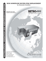
VPRC / VPRH
Single Package Vertical Air Conditioner/Heat Pump
Straight cool/Limited Range Heat pump nominal capacities
9,000 12,000 18,000 19,000 24,000 30,000 36,000 Btuh
2.6 3.5 5.3 5.6 7.0 8.8 10.5 kW
Installation, Operation and
Maintenance Manual
ECR International LLC
2201 Dwyer Avenue
Utica, NY 13501
e-mail: info@RetroAire.com
e Right Fit for Comfort
P/N 240006980, Rev. I [01/15/2010]
An ISO 9001-2000 Certified Company
™

Contents
Table of contents
Read This First ...................................................................................................................................................3
General Product Information ...........................................................................................................................4-5
Verify Unit Before Installing — Model Number ................................................................................................... 6
Verify Unit Before Installing — Operational Performance Data .......................................................................... 7
Verify Unit Before Installing — Dimensional/Physical Data .............................................................................8-9
Verify Unit Before Installing — Responsibilities & Application Limitations ........................................................ 10
Control Box Location .........................................................................................................................................11
Prepare the Enclosure .................................................................................................................................12-13
Install the Wall Sleeve ...................................................................................................................................... 14
Chassis and Wall Sleeve, Typical .....................................................................................................................15
Insert Chassis into Wall Sleeve — FRONT-MOUNTED CONTROL PANEL UNITS ONLY .............................. 16
Insert Chassis into Wall Sleeve — SIDE-MOUNTED CONTROL PANEL UNITS ONLY .................................. 17
Condensate Drain ............................................................................................................................................. 18
Optional return air access panel ....................................................................................................................... 19
Hydronic Coil Option — Performance Data .................................................................................................20-21
Hydronic Coil Option — Assembly and dimensions ....................................................................................22-23
Features ........................................................................................................................................................... 24
Electrical Connections ...................................................................................................................................... 25
Sequence of Operation ..................................................................................................................................... 26
Final Inspection and Start-up .......................................................................................................................27-28
Maintenance and Troubleshooting ..............................................................................................................29-31
Electrical Specications ...............................................................................................................................32-35
Carrier 50QT/ET Replacement Option — Installation .................................................................................36-37
Start-Up Report ................................................................................................................................................ 38
Notes.................................................................................................................................................................39
Inspection
Carefully check the shipment against the bill of lading.
Verify your equipment by using the model nomenclature listed in
Figure 1, Page 6. Make sure chassis, wall sleeve, and louver (as well as
any options) have been received.
Verify unit:
Unit size and type correct per submial sheet and job require-•
ments?
Louver color correct, if special color specied?•
Control box located on correct side? can be factory-installed on •
front, le or right side for models 09–18; eld modiable to le or
right on model 24 only; front side only for models 30–36.
Voltage correct?•
Wall sleeve correct for unit, and the correct depth? [Available in •
depths for walls of 6½ inches (165 mm) or deeper, in increments
of ½ inch (12.7 mm)]
Electric heat correct capacity, if used?•
Hydronic coil included, if required? Piping located as required?•
Other options?•
CAUTION
Inspect each component for damage. Concealed damage
must be reported to the carrier within 15 days of the receipt
of the shipment.
e carrier must make proper notation on the delivery
receipt of all damage identied and complete a carrier
inspection report.
e purchaser must notify ECR International’s Customer
Service department of all damage and is responsible for
ling any necessary claims with the carrier.
Customer Service : (800) 228-9364
Shipping damage MUST be reported to the carrier IMMEDIATELY.
Examine the exterior.
Remove cover and examine compressor and piping for signs of damage.
VPRC/VPRH Single Package Vertical Air Conditioner/Heat Pump
• Installation, Operation and Maintenance Manual •
The Right Fit for Comfort 2 P/N 240006980, Rev. I [01/15/2010]

Read This First
DANGER
e RetroAire™ VPRC/VPRH must:
Be connected to a properly grounded electrical supply •
with the proper voltage as stated on the rating plate.
Have proper overcurrent protection (i.e. time- delay •
fuse/HACR Breaker) as listed on the Rating Plate.
Tampering with the VPRC/VPRH is dangerous and
may result in serious injury or death. Tampering
voids all warranties. Do not aempt to modify or change
this unit in any way.
Failure to follow these instructions can result in a re,
explosion, or electrical shock causing property damage,
personal injury, or death.
WARNING
Safety instructions
is manual is intended as an aid to qualied service per-
sonnel for proper installation, operation, and maintenance
of the VPRC/VPRH Packaged Terminal Air Conditioner
(PTAC). Read these instructions thoroughly and carefully
before aempting installation or operation. Failure to fol-
low these instructions may result in improper installation,
operation, service, or maintenance, possibly resulting in
re, electrical shock, property damage, personal injury,
or death.
Read all instructions before using this unit. Install or lo-
cate this unit only in accordance with these instructions.
Use this unit only for its intended use as described in this
manual.
Check the rating plate on the unit before installation to
make certain the voltage shown is the same as the electric
supply to the unit. e rating plate is located on the front
panel only.
is unit must be connected only to a properly grounded
electrical supply. Do not fail to properly ground this unit.
Turn o the electrical supply before servicing the unit.
Do not use the unit if it has damaged wiring, is not working
properly, or has been damaged or dropped.
[Save these instructions]
Recognize this symbol as an indication
of important safety information.
NOTICE
e VPRC/VPRH is backed by EMI and ECR Interna-
tional and is tested and rated in accordance with AHRI
Standard 390 and UL-484 and UL-1995. Due to ongoing
product development, product designs and specications
may change without notice. Please contact the factory for
more information.
To the installer
Retain this manual and warranty for future reference.
Before leaving the premises, review this manual to be sure
the unit has been installed correctly and run the unit for one
complete cycle to make sure it functions properly.
To obtain technical service or warranty assistance during
or aer the installation of this unit, contact your local
representative. Visit our web site www.retroaire.com for
a local representative listing. For further assistance call
1-800-325-5479.
When calling for assistance, please have the following
information ready:
Model Number_________________________
Serial Number_________________________
Date of installation______________________
WARNING
Completely read all instructions prior to assembling,
installing, operating, or repairing this product.
Inspect all parts for damage prior to installation and start-
up. e VPRC/VPRH PTAC must be installed ONLY by
qualied installation personnel.
VPRC/VPRH Single Package Vertical Air Conditioner/Heat Pump
• Installation, Operation and Maintenance Manual •
P/N 240006980, Rev. I [01/15/2010] 3 Made in USA

General Product Information
Product description
e VPRC/VPRH 09–36 single package vertical air conditioner
(SPVAC) and heat pump (SPVHP) creates new options in layout and
space utilization. e VPRC/VPRH 09–36 oers low cost operation
and quiet, comfortable air distribution, especially when used in multi-
room suites, apartments, health care facilities, and homes.
Each system utilizes environmentally-friendly R-410A refrigerant,
and is supplied with a custom wall sleeve and outdoor louver. e
cabinet is constructed with 20 gauge galvanized steel with a G-90U
corrosion-resistant rating. e insulated top-discharge indoor com-
partment provides quiet, ducted, conditioned air delivery to other
room location(s).
Framed into a concealed closet enclosure for low operating sound
levels, the VPRC/VPRH vertical discharge allows ducting to the top
of the room(s) for superior air circulation and distribution.
All VPRC/VPRH models can be applied in non-ducted return air
applications. e VPRC/VPRH 30-36 can also be applied in ducted
return air applications.
e VPRC/VPRH oers an economic benet when used in a multi-
room suite by supplying conditioned air to more than one room with-
out the need to install additional units. is is also a design advantage
since other rooms will not need an exterior wall to accommodate
additional units.
VPRH models are limited-range heat pumps heat pump operation
will cease at approximately 40°F (4.4°C) outdoor temperature. Utiliz-
ing the electric resistant heat option or the hydronic heat option is rec-
ommended if the heating load of the application will require the unit
to operate in outdoor ambient temperatures below 40°F (4.4°C).
Standard controls and components:
Cooling or heat pump chassis with high eciency rotary, scroll •
or reciprocating type compressors
Custom wall sleeve•
Anodized aluminum outdoor louver for indoor eld installation •
(optional colors available)
R-410A refrigerant•
Ability to utilize single or 2-stage thermostat for VPRH emer-•
gency heat
Front-mounted control box standard for 09–36 (right or le-side •
mounting available for 09–24 only)
Manual fresh air damper for models 09–24 motorized fresh air •
damper for models 30–36
Filter disposable return air lter for models 09–24 only, and a •
washable, reusable return air lter for models 30–36 only
ermostatic drain pan valve for heat pump operation condensate •
removal (VPRH 09, 12, 19–24 only)
Air systems
•
Motors are thermally protected PSC type. Air stream surfaces –
are insulated with
1
/4 inch (6.3 mm) berglass or
1
/8 inch
(3.2 mm) Volara
TM
.
e indoor fan is a forward-curved type directly mounted to –
the motor sha.
Models VPRC/VPRH 09, 12, 19 & 24 blow air across the –
outdoor coil, while models VPRC/VPRH 18, 30 & 36 draw
air through the outdoor coil.
Condensate removal
•
VPRC/VPRH 09, 12, 19 & 24 e outdoor blower incor- –
porates a condensate slinger ring. Base pans are designed to
accommodate a eld-installed drain stub kit if necessary. See
eld installed accessories.
VPRC/VPRH 18, 30 & 36 require an internal drain system. –
Models VPRC/VPRH 18 are supplied standard with an over-
ow drain stub kit for eld installation.
VPRC/VPRH – 30-36 outdoor coil side drain stub is integral to
the base pan, and allows easy connection of the drain line.
Microprocessor control board
•
Universal control board is used in straight cool electric resis- –
tance heat, hydronic heat (models 09–24 only), or cooling/
heat pump applications
Random start timer prevents multiple units from simultane- –
ous start-ups
Fan purge fan remains on for 60 seconds aer heat/cool –
call is satised
Anti-short-cycle compressor protection prevents the compres- –
sor from rapid cycling
Freeze protection prevents evaporator coil freeze up, –
improving compressor reliability
Low ambient lockout prevents compressor operation in out- –
door temperatures less than 40°F (4.4°C)
Test operation all timers are temporarily suppressed to –
allow ease of testing or troubleshooting
Control board LED provides self-diagnostic troubleshooting –
codes (see Sequence of Operation, page 26)
Factory-installed options:
Supplemental electric heat see heat options in Figure 1 •
265/277V (contact factory for availability)•
Corrosion-resistant coil options (sea coast and harsh environ-•
ment usage):
Coated aluminum n/copper tube condenser coil –
Models 09–18 only 10-inch diameter (254 mm) factory-•
installed duct collar
Models 09–12 only Carrier Model 50QT/ET replacement •
conguration
Models 09–24 only Right or le control box mounting•
Models 09–24 only Hydronic heat option•
Models 09–24 only Power disconnect switch ONLY to a •
maximum of 5kW electric heat, or hydronic heat
Field-installed accessories:
Hydronic heat plenum (coil included on models 09–24 only)•
Remote wall thermostat (digital 1-stage or 2-stage available)•
Painted condenser louver (baked enamel/Kynar)•
Return air access panel (standard white, consult factory for custom •
colors w/disposable return air lters) optional solid panel
available for application with separate air intake
Models 09, 12, 19–24 only Drain stub kit can be installed •
on front, right side or le side.
Wall sleeve transition kit Model 30 only - Needed when installing •
a VPRC/VPRH 30 in place of a VPAC/VPHP 30. (See Pg. 15)
VPRC/VPRH Single Package Vertical Air Conditioner/Heat Pump
• Installation, Operation and Maintenance Manual •
The Right Fit for Comfort 4 P/N 240006980, Rev. I [01/15/2010]

General Product Information (continued)
Front — 09, 12, 18, 19, 24
Models 09–24 Models 30–36
Front — 30, 36
Rear — 09, 12, 19, 24
Rear — 18
Control panel, typical
09–24
Wall sleeve,
custom for application
Outside louver
Return
Return
Supply
Supply
Outside louver
Wall sleeve,
custom for application
Control panel, typical
30, 36
Rear — 30, 36
Indoor coil (behind lter)1
Outdoor coil2
Control/power box3
Alternate control box location 4
(right or le side)
ermostatic drain valve
5
(09, 12, 19 and 24 only)
24-volt connection strip
6
Power cord strain relief 7
(for units with power cords)
Line voltage power entrances
8
(for hard-wired units)
Optional disconnect switch
9
Drain stub location options 10
(front, right or le side) ½”
I.D. connection
Fresh air shuer
11
Return air lter (see Table 2, 12
Page 9 for dimensions)
Indoor coil (behind lter)1
Outdoor coil2
Control/power box3
24-volt connection strip4
Line voltage power 5
entrances
Drain stub location ¾”
6
I.D. connection
Motorized fresh air damper
7
switch
Return air lter (see Table 2,
8
Page 9 for dimensions)
1
1
2
3
6
6
9
10
10
10
11
12
7
7
8
8
8
4
3
4
4
5
5
3
3
2
VPRC/VPRH Single Package Vertical Air Conditioner/Heat Pump
• Installation, Operation and Maintenance Manual •
P/N 240006980, Rev. I [01/15/2010] 5 Made in USA

INSTALLATION FOR NEW CONSTRUCTION
Verify Unit Before Installing — Model Number
Model nomenclatureFigure 1
Product Series
VPRC - Straight Cool Unit
VPRH - Heat Pump Unit
Design Revision:
A - Revision Level
Options:
A - NON - Hydronic models
B - Right Hand Piping with Sweat Connections
C - Left Hand Piping with Sweat Connections
D - Front Hand Piping with Sweat Connections
E - Right Hand Piping with Ball Valves and P/T Ports
F - Left Hand Piping with Ball Valves and P/T Ports
G - Front Hand Piping with Ball Valves and P/T Ports
H - Right Hand Piping with Auto Valves
J - Left Hand Piping HYD with Auto Valves
K - Front Hand Piping HYD with Auto Valves
Condenser Coil Option and Filter:
B - Factory Installed Filter
C - Coated Coil and Factory Installed Filter
Compressor Code:
0 - Standard
A - Z Special Option
Compressor Code:
T - Rotary (09-12 Btuh Only)
C - Recip (18, 24, 30, 36 Btuh Only)
S - Scroll (19 Btuh Only)
Options:
A - 10” Round Duct Collar
B - Standard
C - 50QT Option
Heat Options (230 Volts):
0 - No Heat (09-36)
3 - 3kW Elect Heat (09-24 Btuh)
4 - 4kW Elect Heat (09-24 Btuh)
5 - 5kW Elect Heat (09-36 Btuh)
7 - 7kW Elect Heat (19-36 Btuh)
1 - 10kW Elect Heat (19-36 Btuh)
A - 15kW Elect Heat (36 Btuh)
8 - Hydronic Coil (09-24 Btuh)
Controls Options:
1 - Remote, Front Control Access
2 - Remote, Right Control Access
3 - Remote, Left Control Access
4 - Remote, Front Control, Disconnect Switch (2-5kW 09-24 Btuh Only)
5 - Remote, Right Control, Disconnect Switch (2-5kW 09-24 Btuh Only)
6 - Remote, Left Control, Disconnect Switch (2-5kW 09-24 Btuh Only)
Voltage Option:
D - 208/230 - 1 - 60
E - 265/277 - 1 - 60 (Availabilty of 09-12 TBD)
Chassis coding
[verify with rating plate]
Position number: 1 2 3 54 6 7 8 9 10 11 12 13 14 15
Cooling Capacity (Btuh):
09 - 9,000 24 - 24,000
12 - 12,000 30 - 30,000
18 - 17,000 36 - 36,000
19 - 18,000
VPRC/VPRH Single Package Vertical Air Conditioner/Heat Pump
• Installation, Operation and Maintenance Manual •
The Right Fit for Comfort 6 P/N 240006980, Rev. I [01/15/2010]

Verify Unit Before Installing — Operational Performance Data
IMPORTANT
Performance data is subject to change without notice. For the most current unit/
system performance data, please refer to the Enviromaster International listing
of certied products in the ARI certied directory, at www.ahridirectory.org.
Due to ongoing product development, designs, specications, and performance
are subject to change without notice. Please consult the factory for further
information.
Tested/Rated
in Accordance with
ARI Standard 390
VPRC/VPRH 09–36 performance data Table 1
Model Cooling
Btuh (kW)
Sensible
Heat
Ratio
EER Heat Pump
Btuh (kW)
COP Air Flow vs External Static Pressure Fresh
Air
Inlet
Flow
Outdoor
Sound
Level
Static Pressure
0.10 in. w.c.
(2.5 mm
w.c.)
0.20 in. w.c.
(5.1 mm
w.c.)
0.30 in. w.c.
(7.6 mm w.c.)
CFM (L/s) CFM (L/s) CFM (L/s) CFM
(L/s)
dBa
VPRC09 9,000 (2.64) 0.75 9.0 N/A N/A 330 (156) 300 (142) 250 (118)
30 65
VPRH09 9,000 (2.64) 0.75 9.0 9,000 (2.64) 3.0 330 (156) 300 (142) 250 (118)
VPRC12 12,000 (3.51) 0.70 9.0 N/A N/A 440 (208) 385 (182) 350 (165)
35 75
VPRH12 12,000 (3.51) 0.70 9.0 11,400 (3.34) 3.0 440 (208) 385 (182) 350 (165)
VPRC18 17,200 (5.04) 0.71 9.0 N/A N/A 600 (283) 550 (260) 500 (236)
40 71
VPRH18 17,200 (5.04) 0.71 9.0 16,200 (4.75) 3.0 600 (283) 550 (260) 500 (236)
VPRC19 18,400 (5.39) 0.73 9.0 N/A N/A 710 (335) 650 (307) 600 (283)
50 69
VPRH19 18,400 (5.39) 0.73 9.0 16,400 (4.81) 3.0 710 (335) 650 (307) 600 (283)
VPRC24 23,200 (6.80) 0.73 9.0 N/A N/A 710 (335) 650 (307) 600 (283)
60 70
VPRH24 23,200 (6.80) 0.73 9.0 21,600 (6.33) 3.0 710 (335) 650 (307) 600 (283)
VPRC30 31,600 (9.26) 0.69 9.0 N/A N/A 1,190 (562) 1,170 (552) 1,130 (533)
95 69
VPRH30 31,600 (9.26) 0.69 9.0 32,000 (9.38) 3.0 1,190 (562) 1,170 (552) 1,130 (533)
VPRC36
35,600
(10.43)
0.73 9.0 N/A N/A 1,350 (637) 1,290 (609) 1,210 (571)
95 69
VPRH36
35,600
(10.43)
0.73 9.0 36,000 (10.55) 3.0 1,350 (637) 1,290 (609) 1,210 (571)
VPRC/VPRH Single Package Vertical Air Conditioner/Heat Pump
• Installation, Operation and Maintenance Manual •
P/N 240006980, Rev. I [01/15/2010] 7 Made in USA

Verify Unit Before Installing — Dimensional/Physical Data
IMPORTANT
Due to ongoing product development, designs, specications, and performance are subject to change without notice. Please consult
the factory for further information.
VPRC/ VPRH dimensions — inches (mm)Figure 2
B
L
A
J
K
M
C
D
O
TYP
F
E
G
H
REAR
VPRC/VPRH
09, 12, 19 & 24
N
FRONT
16"H X 25"W
RETURN
AIR FILTER
D
C
O
TYP
B
H
A
L
M
K
J
E
G
F
REAR
VPRC/VPRH
18
E
G
J
K
M
A
L
B
D
VPRC/VPRH
30-36
REAR
N
FRONT
16"H X 25"W
RETURN
AIR FILTER
N
FRONT
20"H X 26"W
RETURN
AIR FILTER
VPRC/VPRH Single Package Vertical Air Conditioner/Heat Pump
• Installation, Operation and Maintenance Manual •
The Right Fit for Comfort 8 P/N 240006980, Rev. I [01/15/2010]

Dimensions, shipping weights and return air filter sizesTable 2
Dimension
Model
09–12
in. (mm)
18
in. (mm)
19-24
in. (mm)
30
in. (mm)
36
in. (mm)
A
7
5
/8
(194) 7
3
/4
(197) 6
1
/2
(165) 8
3
/4
(222) 8
3
/4
(222)
B
40(1016) 40(1016) 50(1270) 56(1422) 56(1422)
C
21
7
/16
(545) 21
7
/16
(545) 26
7
/16
(672)
D
25(635) 25(635) 25(635) 28(711) 28(711)
E
14
5
/8
(372) 14
13
/16
(376) 20
5
/8
(524) 21
3
/4
(553) 21
3
/4
(553)
F
25(635) 24
5
/8
(625) 32(813)
G
10
5
/16
(261) 9
13
/16
(249) 11
3
/8
(289) 6
1
/4
(159) 6
1
/4
(159)
H
3
1
/2
(89) 3
1
/2
(89) 3
1
/2
(89)
J
16
1
/2
(419) 16
1
/2
(419) 21
9
/16
(548) 28(711) 28(711)
K
6
1
/8
(156) 6
1
/8
(156) 8
3
/16
(208) 11
1
/4
(286) 11
1
/4
(286)
L
9
5
/8
(245) 9
1
/2
(241) 12(305) 10
1
/4
(260) 10
1
/4
(260)
M
4
1
/4
(108) 4
1
/4
(108) 10
3
/8
(264) 16(406) 16(406)
N
121/2(317) 121/2(317) 121/2(317) 15/8(41) 15/8(41)
O
83/4(222) 83/4(222) 133/4(348)
Model
Shipping weight — pounds (kg)
(shipping weight = unit weight + 60 lbs (27 kg)
Return air filter dimensions — inches (mm)
All models must have an air filter installed prior to operation.
Chassis mounted Return air access panel mounted
09
190(86) 16x25(406x635) 20x20(508x508)
12
190(86) 16x25(406x635) 20x20(508x508)
18
260(118) 16x25(406x635) 20x20(508x508)
19
300(136) 16x25(406x635) 20x30(508x762)
24
300(136) 16x25(406x635) 20x30(508x762)
30
430(195) 20x26(508x660) 20x30(508x762)
36
430(195) 20x26(508x660) 20x30(508x762)
Verify Unit Before Installing — Dimensional/Physical Data (continued)
IMPORTANT
Due to ongoing product development, designs, specications, and performance are subject to change without notice. Please consult
the factory for further information.
VPRC/VPRH Single Package Vertical Air Conditioner/Heat Pump
• Installation, Operation and Maintenance Manual •
P/N 240006980, Rev. I [01/15/2010] 9 Made in USA

Installer responsibilities
is manual has been prepared to acquaint you with the installa-
tion, operation and maintenance of the VPRC/VPRH SPVU and to
provide important safety information in these areas.
Read all instructions thoroughly before aempting the installation
or operation of this unit. is manual should be kept for future refer-
ence.
e manufacturer of this unit will not be liable for any damages caused
by failure to comply with the installation and operating instructions
outlined in this manual.
e installer is solely responsible for ensuring that VPRC/VPRH
units are installed in accordance with all applicable national and
local codes.
A rating plate identifying this unit can be found on the front panel of
the unit. When referring to your unit, always have the information
listed on the rating plate readily available.
Hydronic coil option, when used
IMPORTANT
Hydronic coil option, when used Install the hy-
dronic coil option to the unit BEFORE placing chassis in
the wall sleeve.
See information on the hydronic coil option beginning
on page 20.
For a VPRC/VPRH with optional hydronic heat aached
to the supply air panel, it is still necessary to maintain
minimum spacing between the enclosure and the unit for
proper air ow, but additional space is recommended for
the hydronic option.
Refer to Figure 19, Page 23 of these instructions to de-
termine spacing for serviceability and access to piping
connections.
Verify Unit Before Installing — Responsibilities & Application Limitations
Application limitations
CAUTION
Installer Verify that the ambient temperature conditions
will be within the limits shown in Figure 1.
Contact ECR International’s Sales Department if units
will be operated in temperatures outside the ranges listed
below.
Ambient air limitationsTable 3
OUTDOOR [Ambient air temperature °F (°C)]
COOLING HEATING
Minimum Maximum Maximum
Drybulb Drybulb Drybulb
67(19) 115(46) 75(24)
INDOOR [Ambient air temperature °F (°C)]
COOLING HEATING
Minimum Maximum Min. Max.
Drybulb Wetbulb Drybulb Wetbulb Drybulb
67(19) 57(14) 90(32) 72(22) 50(10) 80(27)
VPRC/VPRH Single Package Vertical Air Conditioner/Heat Pump
• Installation, Operation and Maintenance Manual •
The Right Fit for Comfort 10 P/N 240006980, Rev. I [01/15/2010]

Control box location
Unless otherwise specied, the VPRC/VPRH control box is factory
mounted in the front position.
e control box can be factory mounted for front, le or right side
applications on models 09–24. e control box is available only on
the front for models 30 and 36.
Please specify the preferred control box mounting location when
ordering equipment.
Control box mounting — Models 09–24 — con-Figure 3
trol box can be factory mounted on front (stan-
dard) or, when specified, on the right or left side
Optional control box
locations: right side or left
side (can be relocated in
the field on models 09–12
and models 19–24)
Front-mounted
control box
(standard)
Control box mounting — Models 30 & 36 — Figure 4
front-mounted control box only
Front-mounted
control box
only
Motorized fresh
air damper
switch
location
Control Box Location
Relocating the control box
DANGER
Electrical shock hazard Power to the VPRC/VPRH
MUST be disconnected before servicing or accessing the
control compartment. Failure to do so could result in severe
personal injury or death.
e control box can be factory mounted on the front, le, or right
side on Models 09-24. e control box is only available on the front
for Models 30-36.
Unless otherwise specied, the VPRC / VPRH control box is factory
mounted on the front of the unit. Please specify the preferred control
box mounting location when ordering equipment.
It is possible to relocate the control box on models 09, 12, 19, & 24 in
the eld. is must be done prior to installing the unit. To relocate
the control box:
Determine the desired location of the control box on the unit.1.
Remove the sheet metal panels from the current control box loca-2.
tion, and the desired control box location.
Remove the control knock-out from the panel where the desired 3.
control box location will be.
Remove the insulation directly behind the knock-out.4.
Use metal tape to seal the opening in the panel where the control 5.
box was originally located.
Cut the wire ties that secure the wire harness. is will allow 6.
freedom of movement while relocating the control box.
Remove the mounting screws holding the control box in place.7.
Relocate the control box, and install the mounting screws.8.
Use wire ties to bundle and secure the wire harness. 9.
WARNING
Ensure wires do not contact any sharp sheet metal edges,
refrigeration tubing, the outdoor fan motor, or any mov-
ing parts.
Replace sheet metal panels. 10.
VPRC/VPRH Single Package Vertical Air Conditioner/Heat Pump
• Installation, Operation and Maintenance Manual •
P/N 240006980, Rev. I [01/15/2010] 11 Made in USA

Rough openings
Access opening e access opening must allow for the unit to be
inserted for installation. Provide at least the minimum opening dimen-
sions below. (See Figure 16, Page 19, for dimensions of the opening
when using the option return access panel assembly.)
Minimum access opening dimensions (item 1, Table 4
Figure 6)
Model
Width [inches (mm)] Height [inches (mm)]
Front access
(front control panel)
Side access
(side control panel)
Without
hydronic option
With
hydronic option
09–12
26
1
/8(664) 26
1
/8(664)
45
3
/4
(1162)
55
3
/4
(1416)
18
26
1
/8(664) 26
5
/8(676)
45
3
/4
(1162)
55
3
/4(664)
19–24
26
1
/8(664) 33
5
/8(854)
57
3
/4
(1467)
69
3
/4(664)
30
28
9
/16
(726)
36
1
/4(921)
58
3
/4
(1492)
N/A
36
28
9
/16
(726)
36
1
/4(921)
58
3
/4
(1492)
N/A
Wall sleeve rough opening It is very important that the rough
opening in the wall for the wall sleeve and louver be the correct dimen-
sion and in the exact position necessary for installation.
VPRC/VPRH rough wall sleeve openingTable 5
Model Width [inches (mm)] Height [inches (mm)]
09–12
26
1
/8(664) 26
1
/8(664)
18
26
1
/8(664) 26
5
/8(676)
19–24
26
1
/8(664) 33
5
/8(854)
30
28
9
/16(726) 36
1
/4(921)
36
28
9
/16(726) 36
1
/4(921)
Platform
See Figure 6, Page 13 and Figure 9, Page 15 for details of the platform
and wall sleeve installation. e platform height must make the boom
of the VPRC or VPRH chassis ush with the boom inside edge of the
wall sleeve. is means that the platform surface must be ½ inch (13
mm) ABOVE the boom of the wall sleeve rough opening.
e platform dimensions above will allow the chassis base pan to align
with the boom of the wall sleeve.
Air filter
All models must have an air lter installed prior to operation. Use
the chassis-mounted air lter supplied with the unit unless using the
optional return air access panel. For these applications, remove and
discard the lter from the unit and install the access panel with the
supplied lter in place.
Prepare the Enclosure
Provide proper clearances
NOTE: ECR International recommends installing the unit before any
carpentry work is started for the enclosure.
It is very important for proper air ow and sound levels that a mini-
mum clearance of 4 inches, 102 mm (models 09–18) or 6 inches,
152 mm (models 24–36) between the enclosure and the chassis be
maintained (see Figure 5).
For designed performance, sound levels, and service, maintain a mini-
mum of 6 inches (152 mm) on both sides and front for non-ducted
return air applications only.
Ducted return air applications only require minimal spacing for service
requirements.
Consult ECR International’s Sales Department if these minimums can
not be met. Depending on the application and return air introduction,
some re-conguration can probably be accommodated.
Minimum and maximum operation conditions must be observed
to ensure maximum system performance with minimum service
required.
Minimum clearances around unitFigure 5
Minimum clearances[inches(mm)]
Model A B C
09, 12, 18
4(102) 4(102) 4(102)
19, 24, 30, 36
6(152) 6(152) 6(152)
A=distancefromleftsideofunittointeriorwall
B=distancefromrightsideofunittointeriorwall
C=distancefromfrontofunittointeriorwall
IMPORTANT
Optional return air access panel assembly e
rough opening to the enclosure, and enclosure dimensions
must be sized to accept the access panel door frame, when
used. See page 19 for details.
VPRC/VPRH Single Package Vertical Air Conditioner/Heat Pump
• Installation, Operation and Maintenance Manual •
The Right Fit for Comfort 12 P/N 240006980, Rev. I [01/15/2010]

Prepare the Enclosure (continued)
Exploded view of typical installation (chassis shown is typical of models 09–24)Figure 6
30/36 chassis
(models09–24
shownatright)
6
6
9
10
1
7
89
1
Access opening (for unit insertion/removal) 1
See unit dimensions in Figure 2, Page 9. See
Table 4, page 12 for minimum recommended
opening dimensions. Make sure to account for
the extra height of the hydronic coil module,
if used.
NOTE: e access opening will be in the le
or right side of the enclosure for le or right-
side-mounted control panel units (available
option on models 09–24 only).
See Figure 5, Page 12 for minimum clearances
around unit to determine minimum enclosure
dimensions.
Wall sleeve opening to outside See required
2
dimensions in Table 5, Page 12.
Platform (see page 12) See Figure 9,
3
Page 15 for the required platform height. e
platform MUST be level.
Wall sleeve (see page 14) e wall sleeve
4
must be ordered to accommodate the total wall
thickness (from inside surface of wall sleeve
opening to the surface of the outside wall).
Outside louver- e outside louver aaches
5
to the wall sleeve with nuts placed on the
louver studs.
VPRC/VPRH chassis.
6
Control panel (front standard; available on 7
le side or right side for models 09–24 only).
Access opening must be on the same side of
the unit as the control panel. ermostat
connection terminal block located here.
Optional return access panel assembly. See
8
Figure 16, Page 19 for details and dimensions.
Return air opening
9 EVERY VPRC/VPRH
requires an air lter on the return air. e lter
is located on the chassis opening unless the
optional return air access panel is used (for
these applications, the air lter is removed
from the chassis a lter is installed on the
access panel).
Hydronic coil option See page 20 to
10
page 22.
Prepare the Enclosure (continued)
4
3
5
2
VPRC/VPRH Single Package Vertical Air Conditioner/Heat Pump
• Installation, Operation and Maintenance Manual •
P/N 240006980, Rev. I [01/15/2010] 13 Made in USA

Install the Wall Sleeve
Verify wall sleeve depth
e wall sleeve depth must be suitable for the overall wall thickness.
It is critical that wall thickness be determined before ordering the
wall sleeve (Figure 7).
Consult factory for available wall sleeves.
e minimum wall sleeve depth is for a 6½ inch (165 mm) overall •
wall thickness, and available in ½-inch (13-mm) increments for
thicker walls.
For wall thicknesses less than 6½ inches, the wall sleeve will pen-•
etrate into the room, and will require interior framing adaptations
for proper t.
Verify openings and enclosure
Verify the access opening size, wall sleeve opening size and enclosure
size per page 12.
CAUTION
Verify the wall sleeve opening is square by measuring corner
to corner. Also verify that the platform (if used) is at the
correct height and is level with the wall sleeve opening.
Adjust the platform and framing as necessary. If the opening
and platform are not square, the unit will not t properly
to the wall sleeve.
Assemble the wall sleeve (09–24 only)
Models 09–24 are supplied with a tabbed-assembly wall sleeve. Follow
the instructions supplied with the wall sleeve to assemble. e wall
sleeve should look like that shown in Figure 8. (Note that the wall
sleeves for models 30–36 are factory assembled.)
Secure the wall sleeve
Slide the wall sleeve into the rough opening.1.
Slide the wall sleeve to one side of the opening, preferably to the 2.
side that is most plumb.
Secure the wall sleeve to this side of the opening using screws 3.
through the lag holes (see Figure 8), making sure the wall sleeve
is level. Fill any gaps between the wall sleeve and the opening with
shims to prevent distortion when the screws are tightened.
Secure the wall sleeve to the other side in the same manner. Be 4.
sure the wall sleeve is both square and level before tightening the
screws.
Drip edge will extend
outside exterior wall
when installed to
guide condensate
away from building
VPRC/VPRH WALL
SLEEVE ASSEMBLY
CROSS SECTION
OF TYPICAL WALL
Wall
sleeve
Outdoor louver
Interior
wall
Exterior
wall
Lag Holes
(4 on each
side)
Specify overall wall thickness when
ordering the wall sleeve — it will be
supplied to meet the required depth.
Foam gasket
1
/
2
X
1
/
2
inch
(13 X 13 mm)
Overall wall
thickness
Determining wall sleeve depthFigure 7
Typical tabbed-assembly wall sleeve (09–24)Figure 8
Lag holes
(4 on each side)
Chassis
studs
Inside
Outside
VPRC/VPRH Single Package Vertical Air Conditioner/Heat Pump
• Installation, Operation and Maintenance Manual •
The Right Fit for Comfort 14 P/N 240006980, Rev. I [01/15/2010]

Typical VPRC/VPRH installation, with platformFigure 9
Chassis and Wall Sleeve, Typical
Platform surface must be ½ inch (13 mm) ABOVE
the boom of the wall sleeve rough opening.
To install the outside louver
Install the studs on the inside of the louver. ey 1.
will pass through the clearance holes in the wall
sleeve ange.
Place the outside louver in position.2.
Secure the louver by installing the nuts (supplied) 3.
on the studs.
* Platform surface must be raised an additional 3/8 in (10 mm)
if installing a wall sleeve transition kit. (See Pg 4)
VPRC/VPRH Single Package Vertical Air Conditioner/Heat Pump
• Installation, Operation and Maintenance Manual •
P/N 240006980, Rev. I [01/15/2010] 15 Made in USA

GENERAL INSTALLATION CONTINUED
Insert Chassis into Wall Sleeve —
FRONT-MOUNTED CONTROL PANEL UNITS ONLY
Foam gasket & weather angles — 09–24 — front Figure 10
control panel installations
Foam gasket & weather angles — 30–36 — front Figure 11
control panel installations
Inspect foam insulation
Verify that the foam insulation strips around the condenser opening
are intact (see Figure 10 and Figure 11). Replace if necessary.
e foam insulation must be in place and in good condition to prevent
air or water leakage or air recirculation.
Attach weather angles
See Figure 10 and Figure 11 for the locations of the weather 1.
angles.
Using the screws provided, aach a weather angle to each side of 2.
the chassis as shown in the illustrations.
Insert the chassis into the wall sleeve
Slide the chassis into the wall sleeve, making sure the studs on the 1.
wall sleeve slide through the holes in the back panel and weather
angles.
Apply 2. ¼-20 nuts to the studs that pass through the weather angles,
each side of the chassis.
DO NOT3. apply nuts to the studs that pass through the back panel
of the chassis. is would make removal very dicult.
CAUTION
e chassis must be rmly aached to the wall sleeve to
prevent leakage or recirculation.
See Figure 9, Page 15, for a side view of a typical completed 4.
installation.
Plenum and duct work
Install plenum and duct work to supply air connection, all mod-1.
els.
Install return air duct work, if applicable (VPRH/VPRC 30–36 2.
only).
For models 09–18, an accessory 3.
10-inch round duct collar is
available. Contact ECR Inter-
national’s Sales Department to
order. See gure at right:
Item 1: return air inlet with •
lter installed
Item 2: supply air outlet•
Item 3: optional supply •
air duct collar, 10-inch
(254 mm) round
3
2
1
Back Panel
Weather angle
(one each side)
Mounting
holes (each
side only)
Foam gasket
Foam gaskets
(½ x ½ in)
Supply air
connection
(return is in front)
Punch hole through
gasket at lag holes
Back Panel
Weather
angle
(one each
side)
Mounting
holes (each
side only)
Foam gasket
Supply air
connection
(return is in front)
Punch holes in the foam gaskets at the locations of the
mounting holes in the back panel and weather angles (see
callouts in Figure 12 and Figure 13). is will make it easier
for the wall sleeve studs to pass through the holes when the
chassis is slid into place.
VPRC/VPRH Single Package Vertical Air Conditioner/Heat Pump
• Installation, Operation and Maintenance Manual •
The Right Fit for Comfort 16 P/N 240006980, Rev. I [01/15/2010]

Insert Chassis into Wall Sleeve —
SIDE-MOUNTED CONTROL PANEL UNITS ONLY
Foam gasket & weather angles — 09–24 Figure 12
— right-side control panel installations
Foam gasket & weather angles — 09–24 Figure 13
— left-side control panel installations
Inspect foam insulation
Verify that the foam insulation strips around the condenser opening
are intact (see Figure 12 and Figure 13). Replace if necessary.
e foam insulation must be in place and in good condition to prevent
leakage or recirculation.
Insert the chassis into the wall sleeve
Right-side-mounted1. control panel remove the right side
panel.
Left-side-mounted1. control panel — remove the left side
panel.
Slide the chassis into the wall sleeve, making sure the studs on the 2.
wall sleeve slide through the holes in the back panel.
Apply 3. ¼-20 nuts to the studs that pass through the back panel.
CAUTION
e chassis must be rmly aached to the wall sleeve to
prevent air or water leakage or air recirculation.
Attach weather angle
Right-side-mounted1. control panel
Replace the right side panel.a.
See b. Figure 12 for the location of the right-side weather
angle.
Using the screws provided, aach the weather angle to the c.
chassis as shown in Figure 12.
DO NOT install the le-side weather angle.d.
Apply e. ¼-20 nuts to the studs that pass through the weather
angle.
Left-side-mounted2. control panel
Replace the le side panel.a.
See b. Figure 13 for the location of the right-side weather
angle.
Using the screws provided, aach the weather angle to the c.
chassis as shown in Figure 13.
DO NOT install the right-side weather angle.d.
Apply e. ¼-20 nuts to the studs that pass through the weather
angle.
See Figure 9, Page 15, for a side view of a typical completed 3.
installation.
Plenum and duct work
Install plenum and duct work.1.
Right side
panel
Back panel
Supply air
connection
(return is in front)
Weather angle
(one each side)
Mounting holes
(each side only)
Foam gasket
Foam gaskets
(½ x ½ in)
Punch hole through
gasket at lag holes
Punch holes in the foam gaskets at the locations of the
mounting holes in the back panel and weather angles (see
callouts in Figure 12 and Figure 13). is will make it easier
for the wall sleeve studs to pass through the holes when the
chassis is slid into place.
Left side
panel
Back Panel
Weather
angle (left
side only)
Mounting holes in
weather angle
Foam gasket
Supply air
connection
(return is in front)
Punch hole through
gasket at lag holes
Foam gasket
VPRC/VPRH Single Package Vertical Air Conditioner/Heat Pump
• Installation, Operation and Maintenance Manual •
P/N 240006980, Rev. I [01/15/2010] 17 Made in USA

Condensate Drain
Drain stub location — models 09–24 (optional Figure 14
on models 09, 12, 19 and 24; included and
required on model 18)
Movable drain stub, ½” ID tube connection — can be located
on front, right or left side of unit. Swap gasketed drain stub
plate with blanking plate to relocate to alternate location.
Drain stub location — models 30–36Figure 15
¾” ID tube connection — front of drain pan
Condensate drain
Models VPRC / VPRH 09,12,19, and 24 are designed so that 1.
condensate generated during the cooling operation is delivered
to the base pan, and picked up by the outdoor fan’s slinger ring.
e condensate is slung onto the outdoor coil where it evaporates.
Any excess condensate, or wind driven rain that enters the base
pan will overow through notches located in the rear of the unit
and run out the wall sleeve, onto the drip edge, and out of the
building. Models VPRH 09,12,19, and 24 are also equipped with
a thermostatic drain valve located on the boom of the base pan.
is valve opens when outdoor temperatures reach 500F (100C),
and allows any residual condensate or wind driven rain in the base
pan to run out the wall sleeve as stated above. is feature protects
the outdoor fan from damage during heat pump operation.
An accessory drain stub kit is available for models VPRC / VPRH 2.
09,12,19,and 24. is eld installed kit is designed for use with
the building’s internal drain system, and must be installed prior to
operation. See gure 14 for locations on the base pan, and con-
nection size. If the unit is equipped with aadfqwefqwf drain stub
in the basepan, connect the drain stub to the building’s internal
condensate removal system.
Models VPRC / VPRH 18 are supplied with a drain stub that must 3.
be installed on the unit, and connected to the building’s internal
drain system prior to operation. See gure 14 for locations on the
base pan, and connection size.
Models VPRC / VPRH 30 and 36 are supplied with a drain stub 4.
that must be installed on the unit, and connected to the building’s
internal drain system prior to operation. See gure 15 for location
on the base pan, and connection size.
CAUTION
Drain stub must be connected to an internal condensate
removal system.
VPRC/VPRH Single Package Vertical Air Conditioner/Heat Pump
• Installation, Operation and Maintenance Manual •
The Right Fit for Comfort 18 P/N 240006980, Rev. I [01/15/2010]

Optional return air access panel (with filter)
NOTE
All models must have an air lter installed prior to opera-
tion.
Return air access panels vary by model. When ordering, be sure to
match access panels to units.
Make sure the installation will provide adequate clearance and access
to the control panel.
It is necessary to work closely with the other trades to locate the open-
ing for the return air access panel. e return air access panel must be
installed with enough room available to remove the unit if necessary.
e frame is installed with screws through the lag holes into the frame
studs and should be level and plumb (Figure 16). e return air access
panel is set onto the frame and held in place with 6 screws.
Return air access panel Figure 16 (available with solid doors if ducted return air is used; available in standard white or con-
sult factory for custom colors)
Return air access panel dimensions — inches (mm)Table 6
Model A B C D E F G H J K Item Description
09–18 Std.
29
3
/4
(756)
27
3
/4
(705)
47
3
/4
(1213)
30
(762)
17
3
/4
(451)
20
1
/4
(514)
20
(508)
20
(508)
50
(1270)
45
3
/4
(1162)
1
Solid door panel (for ducted return air installations)
2
Door assembly, front view
19–24 Std.
29
3
/4
(756)
27
3
/4
(705)
59
3
/4
(1518)
30
(762)
28
(711)
20
1
/4
(514)
30
(762)
20
(508)
62
(1518)
57
3
/4
(1467)
3
Door assembly, rear view
4
Filter bracket (on back)
30–36 Std.
35
7
/8
(911)
33
15
/16
(862)
60
(1524)
36
1
/8
(918)
17
5
/8
(448)
33
9
/16
(852)
30
(762)
20
(508)
62
3/16
58
(1473)
5
Frame assembly (items 5a are lag holes, 3 per side)
6
Filter
Return air access panel part numbers
(includes items 2, 5 and 6 below)
09–18 Part # 240003010C
19–24 Part # 240003013C
30–36 Part # 240004439C
Optional return air access panel
VPRC/VPRH Single Package Vertical Air Conditioner/Heat Pump
• Installation, Operation and Maintenance Manual •
P/N 240006980, Rev. I [01/15/2010] 19 Made in USA

Hydronic Coil Option — Performance Data
1, 2, 3, 4, 5, 6, 7 8 9 10 11 12 13 14 15
H H F 7 1 1 1 9 B A B A A 0 A
Series:
Revision:
A - Revision Level
Piping:
Special -Standard:
R - Right Side 0 - Standard
L - Left Side A - Z Special Option
F - Front
Capacity:
Shipping:
0 - 09 - 18 A - Single (STD)
1 - 19 - 24
Chassis Configuration:
OEM:
1 - Remote A - RetroAire (STD)
X - Special
Aux Heat:
Motorized Valve
8 - 1 Row (09 - 18
)
B - 24V, 3 Way N / C Valve (STD)
9 - 2 Row (19 - 24
)
X - Special
Pipe Connection:
Shut Off Valves:
B - Standard A - Sweat Connections (STD)
B - Ball Valves & P/T Ports
C - Automatic Balancing Valves
X - Special
Position:
Example:
Hydronic coil option nomenclature (order as described below to obtain required coil and accessories)Figure 17
HH Series Hydronic Coil Option
(Available for VPRC / VPRH models 09-24 only)
IMPORTANT
Install the hydronic coil option to the unit BEFORE placing
chassis in the wall sleeve.
e coil package comes with a sheet metal enclosure. An 2- or 3-way
motorized 24v water valve is available (models 09–24 only). Verify
that the hydronic coil package is either le, right or front aligned,
matching the control section alignment of the unit on which it is to
be installed.
e coil package must be centered on top of the VPRC/VPRH 1.
chassis. Make sure it is centered over the fan discharge and that
the piping package is in the correct position.
Find the two “Z” mounting brackets used to clamp the hydronic 2.
enclosure to the chassis top. Mount these brackets to the chas-
sis top using the holes provided. is will allow the chassis to
be pulled out for service/maintenance without disturbing the
hydronic package.
Complete the piping of the hydronic package, including eld sup-3.
plied shut o valves and other eld supplied items.
Install threaded rods through the slots in the brackets (Figure 18), 4.
place a washer and nut on the threaded rod, and tighten the nut
to secure it in place. e upper end of the threaded rod should be
secured to angle iron or 2 x 4 inch (51 x 102 mm) wood. Make
sure that the rods do not interfere with the chassis plenum or duct
work. ese rods will hold the hydronic package in place when
the chassis is removed for maintenance.
IMPORTANT
System duct work is connected to the discharge opening on
the duct collar or plenum. A ex collar is advised.
Standard Features
20 Ga. Galvanized G90U sheet metal enclosure.•
Front, Le or Right side piping connections.•
½” sweat connections•
24V, 3 way, normally closed motorized valve. •
10” diameter supply air duct connection. •
Optional Features
Ball valves & P/T ports•
Automatic balancing valves with P/T ports and shut-o•
Refer to Figure 17, page 20 for HH series nomenclature to order •
the hydronic coil that meets your needs.
VPRC/VPRH Single Package Vertical Air Conditioner/Heat Pump
• Installation, Operation and Maintenance Manual •
The Right Fit for Comfort 20 P/N 240006980, Rev. I [01/15/2010]
/