
March1993
Form:
OM-160518
Effective
With
Serial
No.
KD398640
OWNERS
MANUAL
Read
and
follow
these
instructions
and
all
Give
this
manual
to
the
operator.
safety
blocks
carefully.
Have
only
trained
and
qualified
persons
install,
operate,
or
service
this
unit.
Call
your
distributor
if
you
do
not
understand
the
directions.
For
help,
call
your
distributor
or:
MILLER
ELECTRIC
Mfg.
Co.,
P.O.
Box
1079,
Appleton,
WI
54912
414-734-9821
Millerfi
~.
r.~1~Ic4...1
-
~_
~
I
1
~.w
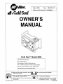
Gold
SealTM
Model
3000
CC/DC
Welding
Generator
For
SMAW
Welding
90
Amperes,
25
Volts
DC
At
60%
Duty
Cycle
1.2
kVA/kW
DC
Auxiliary
Power
With
Overload
Protection
Kohler
CH5+
Air-Cooled,
Four-Cycle,
Gasoline
Engine
Optional
Low
Oil
Pressure
Shutdown
Switch
coven
5/92ASt-161
477
PRINTED
IN
~SA


s
a
MILLERS
TRUE
BLUETM
LIMITED
WARRANTY
Effective
January
1,
1992
(Equipment
with
a
serial
number
preface
of
KC
or
newer)
This
limited
warranty
supersedes
all
previous
MILLER
warranties
end
is
exclusive
with
no
other
guerantees
or
warranties
eapressed
or
Implied.
u
LIMITED
WARRANTY
Subject
to
the
terms
end
conditions
below,
MILLER
Electric
MIg.
Co.,
Appleton.
Wisconsin,
wsrrsnts
to
its
originsl
retell
purchsser
that
new
MILLER
equipment
sold
sfter
the
effective
date
of
this
limited
warranty
is
tree
of
de
tects
in
material
end
workmanship
at
the
time
it
is
shipped
by
MILLER.
THIS
WAR
RANT?
IS
EXPRESSLY
IN
LIEU
OF
ALL
OTHER
WARRANTIES.
EXPRESS
OR
IMPLIED,
INCLUDING
THE
WARRANTIES
OF
MERCHANTABILITY
AND
FIT
NESS.
Within
the
warranty
periods
listed
below,
MILLER
will
repair
or
replace
any
war
ranted
pans
or
components
that
tall
due
to
such
detects
in
material
or
workmanship.
MILLER
must
be
notified
in
writing
within
thiny
(30)
days
of
such
defect
or
failure,
at
which
lime
MILLER
will
provide
instructions
on
the
warranty
claim
procadurea
to
be
followed.
MILLER
shall
honor
warranty
claims
on
warranted
equipment
listed
below
in
the
event
of
such
a
failure
within
the
warranty
time
periods.
All
warranty
lime
periods
start
on
the
date
that
the
equipment
was
delivered
to
the
original
retail
purchaser,
and
are
as
follows:
1.
5
Yearn
Pans
3
Years
Labor
*
Original
main
power
rectifiers
2.
3
Yearn
Pans
and
Labor
*
Transformer/Rectifier
Power
Sources
Plasma
Arc
Cutting
Power
Sources
Semi-Automatic
and
Automatic
Wire
Feeders
*
Robots
3.
2
Years
Pans
and
Labor
Engine
Driven
Welding
Generators
(NOTE:
Engines
are
warranted
separately
by
the
angina
manufacturer.)
4.
I
Year
Pans
and
Labor
*
Motor
Driven
Guns
*
Process
Controllers
*
Water
Coolant
Systems
HF
Units
*
Grids
Spot
Welders
*
Load
Banks
SDX
Transformers
Running
Gear/Trailers
*
Fietd
Options
(NOTE:
Field
options
are
covered
under
True
BIuenM
for
the
remaining
warranty
period
ol
the
product
they
are
installed
in,
or
for
a
minimum
of
one
yaar
whichever
is
greater.)
5.
6
Months
Batteries
6.
90
Days
Pans
and
Labor
*
MIS
Guns/TIG
Torches
*
Plasma
Cutting
Torches
*
Remote
Controls
*
Accessory
Kits
*
Replacement
Pans
MILLERS
True
BiuanM
Limited
Warranty
shall
not
apply
to:
1.
Items
furnished
by
MILLER,
but
manufactured
by
others,
such
as
anginea
or
trade
accessories.
These
items
are
covered
by
the
manufacturers
warranty,
it
any.
2.
Consumabla
components;
such
as
contact
tips,
cutting
nozzles,
conlaclorn
and
relays.
3.
Equipment
that
has
bean
modilied
by
any
party
other
than
MILLER.
or
equip
ment
that
has
been
improperly
installed,
improperly
operated
or
misused
based
upon
industry
standards,
or
aquipmenl
which
has
not
had
reasonable
and
necessary
maintenance,
or
equipment
which
han
bean
used
for
operation
outside
of
the
spacifications
br
the
equipment.
MILLER
PRODUCTS
ARE
INTENDED
FOR
PURCHASE
AND
USE
BY
COMMER
CIALJINDUSTRIAL
USERS
AND
PERSONS
TRAINED
AND
EXPERIENCED
IN
THE USE
AND
MAINTENANCE
OF
WELDING
EOUIPMENT
In
the
avant
01
a
warranty
claim
covarad
by
this
warranty,
the
eacluniva
remedies
shall
ba,
at
MILLERS
option:
(1)
repair;
or
(2)
replacement;
or,
where
authorized
in
writing
by
MILLER
in
appropriate
cases.
(3)
the
reasonabia
cost
of
repair
or
replace
ment
alan
authorized
MILLER
service
station;
or
(4)
payment
of
or
credit
for
the
pur
chase
price
(lass
reasonable
depracialion
based
upon
actual
usa)
upon
return
of
the
goods
at
customers
risk
and
expense.
MILLERS
option
of
repair
or
replacement
will
ba
FOB.,
Factory
atAppleton,
Wisconsin,
or
P.0.6.
at
a
MILLER
authorized
ser
vice
facility
as
determined
by
MILLER.
Therefore
no
compensation
or
raimburse
went
for
transportation
costs
of
any
kind
will
be
allowed.
TO
THE
EXTENT
PERMITTED
BY
LAW,
THE
REMEDIES
PROVIDED
HEREIN
ARE
THE
SOLE
AND
EXCLUSIVE
REMEDIES.
IN
NO
EVENT
SHALL
MILLER
BE
LIABLE
FOR
DIRECT,
INDIRECT,
SPECIAL.
INCIDENTAL
OR
CONSEOUENTIAL
DAMAGES
(INCLUDING
LOSS
OF
PROFIT).
WHETHER
BASED
ON
CON
TRACT,
TORT
OR
ANY
OTHER
LEGAL
THEORY.
ANY
EXPRESS
WARRANTY
NOT
PROVIDED
HEREIN
AND
ANY
IMPLIED
WAR
RANTY,
GUARANTY
OR
REPRESENTATION
AS
TO
PERFORMANCE,
AND
ANY
REMEDY
FOR
BREACH
OF
CONTRACT
TORT
DR
ANY
OTHER
LEGAL
THEORY
WHICH.
BUT
FOR
THIS
PROVISION,
MIGHT
ARISE
BY
IMPLICATION,
OPERATION
OF
LAW.
CUSTOM
OF
TRADE
OR
COURSE
OF
DEALING.
IN
CLUDING
ANY
IMPLIED
WARRANTY
OF
MERCHANTABILITY
OR
FITNESS
FOR
PARTICULAR
PURPOSE.
WITH
RESPECT
TO
ANY
AND
ALL
EOUIPMENT
FURNISHED
BY
MILLER
IS
EXCLUDED
AND
DISCLAIMED
BY
MILLER.
Some
slates
in
the
U.S.A.
do
not
allow
limitations
of
how
long
an
implied
warranty
lasts,
or
the
esciusion
of
incidental,
indirect,
special
or
consequential
damages,
ao
the
above
liwitatlon
or
exclusion
may
not
apply
to
you.
This
warranty
provides
spa
citic
legal
rights,
and
other
rights
may
be
available,
but
may
vary
from
stale
to
stale.
In
Canada,
legislation
in
some
provinces
provides
br
certain
additional
warranties
or
remedies
other
than
as
staled
herein,
and
to
the
astant
that
they
may
not
ba
waived.
Ihe
limitations
and
exclusions
set
out
above
may
not
apply.
This Limited
Warranty
provides
specific
legal
rights,
and
other
rights
may
be
available,
but
may
vary
Irom
province
to
province.
I
r
_____________________________
I
RECEIVING-HANDLING
Before
unpacking
equ(pment,
check
carton
for
any
damage
that
may
have
occurred
during
Shipment.
File
any
claims
for
loss
or
damage
with
the
delivering
carrier.
Assistance
for
filing
or
settling
claims
may
be
obtained
from
distributor
and/or
equipment
manufacturers
Transportation
Department.
When
requesting
infDrmation
about
this
equipment,
always
provide
Mode)
Designation
and
Serial
or
Sty(e
Number.
USe
the
following
spaces
to
record
Model
Designation
and
Serial
or
Style
Number
of
your
unit.
The
information
is
located
on
the
rating
label
or
namep(ate.
Model
__________
Serial
or
Style
No.
Date
of
Purchase
miller
5192


March
1
993
Form:
OM-160
518
Effective
With
Serial
No.
KD398640
OWNERS
MANUAL
U
Read
and
follow
these
instructions
and
all
U
Give
this
manual
to
the
operator.
U
U
safety
blocks
carefully.
Have
only
trained
and
qualified
persons
install,
operate,
or
service
this
unit.
Callyourdistributorifyoudonotunderstand
the
directions.
rt~i
U
U
For
help,
call
your
distributor
or:
MILLER
ELECTRIC
Mfg.
1079,
Appleton,
WI
54912
Co.,
P.O.
Box
414-734-9821
1~oIsfi
(jJOJ1
cI~j\r~J~
PAW
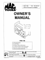
100
CC/DC
Welding
Generator
For
SMAW
Welding
U
90
Amperes,
25
Volts
DC
At
60%
Duty Cycle
U
1.2
kVAJkW
DC
Auxiliary
Power
With
Overload
Protection
Kohler
CH5+
Air-Cooled,
Four-Cycle,
Gasoline
Engine
Optional
Low
Oil
Pressure
Shutdown
Switch
cover
8/92
ST-161
477
PRINTED
IN
~SA


ARC
WELDING
SAFETY
PRECAUTIONS
5.
Properly
install
and
ground
this
equipment
according
to
its
Owners
Manual
and
national,
state,
and
local
codes.
6.
When
making
input
connections,
attach
proper
grounding
conductor
first.
7.
Turn
off
all
equipment
when
not
in
use.
8.
Do
not
use
worn,
damaged,
undersized,
or
poorly
spliced
cables.
9.
Do
not
wrap
cables
around
your
body.
10.
Ground
the
workpiece
to
a
good
electrical
(earth)
ground.
11.
Do
not
touch
electrode
if
in
contact
with
the
work
or
ground.
12.
Use
only
well-maintained
equipment.
Repair
or
replace
damaged
parts
at
once.
13.
Wear
a
safety
harness
if
working
above
floor
level.
14.
Keep
all
panels
and
covers
securely
in
place.
ARC
RAYS
can
burn
eyes
and
skin;
NOISE
can
damage
hearing.
Arc
rays
from
the
welding
process
produce
intense
heat
and
strong
ultraviolet
rays
that
can
burn
eyes
and
skin.
Noise
from
some
processes
can
damage
hearing.
ARC
RAYS
2.
Wear
a
welding
helmet
fitted
with
a
proper
shade
of
filter
(see
ANSI
Z49.
1
listed
in
Safety
Standards)
to
protect
your
face
and
eyes
when
welding
or
watching.
3.
Wear
approved
safety
glasses.
Side
shields
recommended.
4.
Use
protective
screens
or
barriers
to
protect
others
from
flash
and
glare;
warn
others
not
to
watch
the
arc.
5.
Wear
protective
clothing
made
from
durable,
flame-resistant
material
(wool
and
leather)
and
foot
protection.
FUMES
AND
GASES
can
be
hazardous
to
your
health.
Welding
produces
fumes
and
gases.
Breathing
these
fumes
and
gases
can
be
hazardous
to
your
health.
Keep
your
head
out
of
the
fumes.
Do
not
breathe
the
fumes.
If
inside,
ventilate
the
area
and/or
use
exhaust
at
the
arc
to
remove
welding
fumes
and
gases.
If
ventilation
is
poor,
use
an
approved
air-supplied
respirator.
Read
the
Material
Safety
Data
Sheets
(MSDS5)
and
the
manufacturers
instruction
for
metals,
consumables,
coatings,
and
cleaners.
5.
Work
in
a
confined
space
only
if
it
is
well
ventilated,
or
while
wearing
an
air-supplied
respirator.
Shielding
gases
used
for
welding
can
displace
air
causing
injury
or
death.
Be
sure
the
breathing
air
is
safe.
6.
Do
not
weld
in
locations
near
degreasing,
cleaning,
or
spraying
operations.
The
heat
and
rays
of
the
arc
can
react
with
vapors
to
form
highly
toxic
and
irritating
gases.
7.
Do
not
weld
on
coated
metals,
such
as
galvanized,
lead,
or
cadmium
plated
steel,
unless
the
coating
is
removed
from
the
weld
area,
the
area
is
well
ventilated,
and
if
necessary,
while
wearing
an
air-supplied
respirator.
The
coatings
and
any
metals
containing
these
elements
can
give
off
toxic
fumes
if
welded.
WELDING
can
cause
fire
or
explosion.
Sparks
and
spatter
fly
off
from
the
welding
arc.
The
flying
sparks
and
hot
metal,
weld
spatter,
hot
workpiece,
and
hot
equipment
can
cause
fires
and
burns.
Accidental
contact
of
electrode
orwelding
wire
to
metal
objects
can
cause
sparks,
overheating,
or
fire.
Protect
yourself
and
others
from
flying
sparks
and
hot
metal.
Do
not
weld
where
flying
sparks
can
strike
flammable
material.
Remove
all
flammables
within
35
ft
(10.7
m)
of
the
welding
arc.
If
this
is
not
possible,
tightly
cover
them
with
approved
covers.
Be
alert
that
welding
sparks
and
hot
materials
from
welding
can
through
small
cracks
and
openings
to
adjacent
areas
FLYING
SPARKS
AND
HOT
METAL
can
cause
injury.
Chipping
and
grinding
cause
flying
metal.
As
welds
cool,
they
can
throw
off
slag.
Watch
for
fire,
and
keep
a
fire
extinguisher
nearby.
Be
aware
that
welding
on
a
ceiling,
floor,
bulkhead,
or
partition
can
cause
fire
on
the
hidden
side.
Do
not
weld
on
closed
containers
such
as
tanks
or
drums.
Connect
work
cable
to
the
work
as
close
to
the
welding
area
as
practical
to
prevent
welding
current
from
traveling
long,
possibly
unknown
paths
and
causing
electric
shock
and
fire
hazards.
Do
not
use
welder
to
thaw
frozen
pipes.
Remove
stick
electrode
from
holder
or
cut
off
welding
wire
at
contact
tip
when
not
in
use.
11.
Wear
oil-free
protective
garments
such
as
leather
gloves,
heavy
shirt,
cuffless
trousers,
high
shoes,
and
a
cap.
1.
Wear
approved
face
shield
or
safety
goggles.
Side
shields
recommended.
2.
Wear
proper
body
protection
to
protect
skin.
a
WARNING
ARC
WELDING
can
be
hazardous.
PROTECT
YOURSELF
AND
OTHERS
FROM
POSSIBLE
SERIOUS
INJURY
OR
DEATH.
KEEP
CHILDREN
AWAY.
PACEMAKER
WEARERS
KEEP
AWAY
UNTIL
CONSULTING
YOUR
DOCTOR.
In
welding,
as
in
most
jobs,
exposure
to
certain
hazards
occurs.
Welding
is
safe
when
precautions
are
taken.
The
safety
information
given
below
is
only
a
summary
of
the
more
complete
safety
information
that
will
be
found
in
the
Safety
Standards
listed
on
the
next
page.
Read
and
follow
all
Safety
Standards.
HAVE
ALL
INSTALLATION,
OPERATION,
MAINTENANCE,
AND
REPAIR
WORK
PERFORMED
ONLY
BY
QUALIFIED
PEOPLE.
ELECTRIC
SHOCK
can
kill.
Touching
live
electrical
parts
can
cause
fatal
shocks
or
severe
burns.
The
electrode
and
work
circuit
is
electrically
live
whenever
the
output
is
on.
The
input
power
circuit
and
machine
internal
circuits
are
also
live
when
power
is
on.
In
semiautomatic
or
automatic
wire
welding,
the
wire,
wire
reel,
drive
roll
housing,
and
all
metal
parts
touching
the
welding
wire
are
electrically
live.
Incorrectly
installed
or
improperly
grounded
equipment
is
a
hazard.
1.
Do
not
touch
live
electrical
parts.
2.
Wear
dry,
hole-free
insulating
gloves
and
body
protection.
3.
Insulate
yourself
from
work
and
ground
using
dry
insulating
mats
or
covers.
4.
Disconnect
input
power
or
stop
engine
before
installing
or
servicing
this
equipment.
1.
Use
approved
ear
plugs
or
ear
muffs
if
noise
level
is
high.
1.
2.
3.
4.
1.
2.
3.
4.
5.
6.
7.
8.
9.
10.
srI
9/92


MOVING
PARTS
can
cause
injury.
Moving
parts,
such
as
fans,
rotors,
and
belts
can
cut
fingers
and hands
and
catch loose
clothing.
1.
Keep
all
doors,
panels,
covers,
and
guards
closed
and
securely
in
place.
2.
Stop
en
me
before
installing
or
connecting
unit.
Safety
in
Welding
and
Cutting,
ANSI
Standard
Z49.1,
from
American
Welding
Society,
550
N.W.
LeJeune
Rd,
Miami
FL
33126
Safety
and
Health
Standards,
OSHA
29
CFR
1910,
from
Superinten
dent
of
Documents,
U.S.
Government
Printing
Office,
Washington,
D.C.
20402.
Recommended
Safe
Practices
for
the
Preparation
for
Welding
and
Cutting
of
Containers
That
Have
Held
Hazardous
Substances,
Ameri
can
Welding
Society
Standard
AWS
F4.i
from
American
Welding
So
ciety,
550
N.W.
LeJeune
Rd,
Miami,
FL
33126
National
Electrical
Code,
NFPA
Standard
70,
from
National
Fire
Pro
tection
Association,
Batterymarch
Park,
Quincy,
MA
02269.
ENGINES
can
be
hazardous.
1.
Use
equipment
outside
in
open,
well-ventilated
areas.
2.
If
used
in
a
closed
area,
vent
engine
exhaust
outside
and
away
from
any
building
air
intakes.
1.
Stop
engine
before
checking
or
adding
fuel.
2.
Do
not
add
fuel
while
smoking
or
if
unit
is
near
any
sparks
or
open
flames.
3.
Allow
engine
to
cool
before
fueling.
If
possible,
check
and add
fuel
to
cold
engine
before
beginning
job.
4.
Do
not
overfill
tank
allow
room
for
fuel
to
expand.
5.
Do
not
spill
fuel.
If
fuel
is
spilled,
clean
up
before
starting
engine.
3.
Have
only
qualified
people
remove
guards
or
covers
for
maintenance
and
troubleshooting
as
necessary.
4.
To
prevent
accidental
starting
during
servicing,
disconnect
negative
()
battery
cable
from
battery.
5.
Keep
hands,
hair,
loose
clothing,
and
tools
away
from
moving
parts.
6.
Reinstall
panels
or
guards
and
close
doors
when
servicing
is
finished
and
before
starting
engine.
Safe
Handling
of
Compressed
Gases
in
Cylinders,
CGA
Pamphlet
P-i,
from
Compressed
Gas
Association,
1235
Jefferson
Davis
High
way,
Suite
501,
Arlington,
VA
22202.
Code
for
Safety
in
Welding
and
Cutting,
CSA
Standard
Wi
17.2,
from
Canadian
Standards
Association,
Standards
Sales,
178
Rexdale
Bou
levard,
Rexdale,
Ontario,
Canada
M9W
1R3.
Safe
Practices
ForOccupationAnd
Educational
Eye
And
Face
Protec
tion,
ANSI
Standard
Z87.1,
from
American
National
Standards
Institute,
1430
Broadway.
New
York,
NY
10018.
Cutting
And
Welding
Processes,
NFPA
Standard
51
B,
from
National
Fire
Protection
Association,
Batterymarch
Park,
Quincy,
MA
02269.
IL~c
CYLINDERS
can
explode
if
damaged.
Shielding
gas
cylinders
contain
gas
under
high
pressure.
If
damaged,
a
cylinder
can
explode.
Since
gas
cylinders
are
normally
part
of
the
welding
process,
be
sure
to
treat
them
carefully.
Protect
compressed
gas
cylinders
from
excessive
heat,
mechanical
shocks,
and
arcs.
2.
Install
and
secure
cylinders
in
an
upright
position
by
chaining
them
to
a
stationary
support
or
equipment
cylinder
rack
to
prevent
falling
or
tipping.
3.
Keep
cylinders
away
from
any
welding
or
other
electrical
circuits.
4.
Never
allow
a
welding
electrode
to
touch
any
cylinder.
5.
Use
only
correct
shielding
gas
cylinders,
regulators,
hoses,
and
fittings
designed
for
the
specific
application;
maintain
them
and
associated
parts
in
good
condition.
6.
Turn
face
away
from
valve
outlet
when
opening
cylinder
valve.
7.
Keep
protective
cap
in
place
over
valve
except
when
cylinder
is
in
use
or
connected
for
use.
8.
Read
and
follow
instructions
on
compressed
gas
cylinders.
associated
equipment,
and
CGA
publication
P-i
listed
in
Safety
Standards.
a
WARNING
ENGINE
EXHAUST
GASES
can
kill.
Engines
produce
harmful
exhaust
gases.
ENGINE
FUEL
can
cause
fire
or
explosion.
Engine
fuel
is
highly
flammable.
SPARKS
can
cause
BATTERY
GASES
1.
Always
wear
a
face
shield
when
working
on
a
battery.
TO
EXPLODE;
BATTERY
ACID
can
2.
Stop engine
before
disconnecting
or
connecting
battery
burn
eyes
and
skin,
cables.
Batteries
contain
acid
and
generate
explosive
gases.
3.
4.
5.
Do
not
allow
tools
to
cause
sparks
when
working
on
a
battery.
Do
not
use
welder
to
charge
batteries
or
iump
start
vehicles.
Observe
correct
polarity
(+
and
)
on
batteries.
4
~
.
(.~
~
~
STEAM
AND
COOLANT
can
skin.
The
coolant
in
the
under
pressure.
PRESSURIZED
burn
face,
eyes,
radiator
can
be
very
h
HOT
and
ot
and
1.
2.
3.
Do
not
remove
radiator
cap
when
engine
is
hot.
Allow
engine
to
cool.
Wear
gloves
and
put
a
rag
over
cap
area
when
removing
cap.
Allow
pressure
to
escape
before
completely
removing
cap.
PRINCIPAL
SAFETY
STANDARDS
Sri
9/92


TABLE
OF
CONTENTS
SECTION
1
-
SAFETY
SIGNAL
WORDS
.
SECTION
2
SPECIFICATIONS
2-1.
Volt-Ampere
Curves
2-2.
Duty
Cycle
2-3.
Fuel
Consumption
2-4.
DC
Auxiliary
Power
Curve
SECTION
3INSTALLATION
3-1.
Selecting
A
Location
And
Moving
Welding
Generator
3-2.
Engine
Prestart
Checks
3-3.
Grounding
The
Generator
Auxiliary
Power
System
3-4.
Connecting
To
Weld
Output
Terminals
SECTION
4OPERATING
THE
WELDING
GENERATOR
SECTION
5
OPERATING
AUXILIARY
EOUIPMENT
5-1.
Auxiliary
Power
DC
Receptacle
5-2.
Auxiliary
Equipment
Operation
1
11
12
13
13
14
14
15
16
22334566
7
10
10
SECTION
6
MAINTENANCE
&
TROUBLESHOOTING
6-1.
Routine
Maintenance
6-2.
Changing
Engine
Oil
6-3.
Adjusting
Engine
Speed
6-4.
Air
Cleaner
Service
6-5.
Clean
Air
Intake
And
Cooling
Areas
6-6.
Drive
Belt
Adjustment
And
Replacement
6-7.
Overload
Protection
6-8.
Troubleshooting
SECTION
7
ELECTRICAL
DIAGRAMS
SECTION
8-
WELDING
METHODS
&
TROUBLESHOOTING
8-1.
Shielded
Metal
Arc
Welding
(SMAW)
8-2.
Welding
Troubleshooting
SECTION
9
PARTS
LIST
Figure
9-1.
Main
Assembly
Figure
9-2.
Panel,
Front
w/Components
Figure
9-3.
Panel,
Control
w/Components
18
20
25
28
31
32
OM.160
518
3)93


SECTION
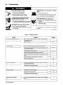
1
SAFETY
SIGNAL
WORDS
Read
all
safety
messages
throughout
this
manual.
Obey
all
safety
messages
to
avoid
injury.
Learn
the
meaning
of
WARNING
and
CAUTION.
Figure
1-1.
Safety
Information
SECTION
2
SPECIFICATIONS
Table
2-1.
Welding
Generator
rnodl.1
2/93
1
2
2
\
a
CAUTION
/
;
3
_______________
______________
ELECTRIC
SHOCK
can
kill
MOVING
PARTS
can
injure.
L~
I
Disconnect
input
power
betore~
~
Keep
all
panels
and
covers
closed
I
I
Do
not
touch
live
electrical
parts.
Keep
away
from
moving
parts,
I
installing
or
servicing.
when
operating.
I
5
READ
SAFETY
BLOCKS
at
start
of
6
Section
3-1
before
proceeding
7H
NOTE
~
1
Safety
Alert
Symbol
2
Signal
Word
WARNING
means
possible
death
or
serious
injury
can
happen.
CAUTION
means
possible
minor
injury
or
equipment
damage
can
happen.
3
Statement
Of
Hazard
And
Result
4
Safety
Instructions
To
Avoid
Hazard
5
Hazard
Symbol
(If
Available)
6
Safety
Banner
Read
safety
blocks
for
each
sym
bol
shown.
7
NOTE
Special
instructions
for
best
oper
ation
not
related
to
safety.
Turn
Off
switch
when
using
high
frequency.
Specification
Type
Of
Output
Rated
Weld
Output
Amperage
Range
Maximum
Open-Circuit
Voltage
Welding
Process
Description
Auxiliary
Power
Rating
Engine
Engine
Speed
(No
Load)
Fuel
Tank
Capacity
Engine
Oil
Capacity
Drive
Belt
Size
Overall
Dimensions
Weight
Options
Constant
Current/Direct
Current
(CC/DC)
90
Amperes,
25
Volts
DC
At
60%
Duty
Cycle
(See
Section
2-2)
40
To
100
A
75
Volts
DC
(See
Section
2-1)
Shielded
Metal
Arc
Welding
(SMAW);
Flux
Cored
Arc
Welding
(FCAW)
And
Gas
Tungsten
Arc
Welding
(GTAW)
Possible
With
Appropriate
Process
Options
1.2
kW,
120
Volts
DC,
10
Amperes
Kohler
CH5+
Air-Cooled,
One-Cylinder,
Four-Cycle
Gasoline
Engine
1800
rpm
Idle
Speed;
4150
rpm
Weld
And
Power
Speed
2.3
U.S.
gal
(8.7L)
22.4
oz
(0.66L)
1/2
x
.343
x
32.3
Cogged
See
Figure
3-2
Net:
101
lb
(46
kg);
Ship:
113
lb
(51
kg)
See
Rear
Cover
OM-160
518
Page
1


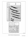
2-1.
Volt-Ampere
Curves
Figure
2-1.
Volt-Ampere
Curves
2-2.
Duty
Cycle
a
CAUTION
300
-
250
-
200
U)
150
w
a
<
100
.
75
.
Figure
2-2.
Duty
Cycle
Chart
Cl)
0
>
0
100
90
80
70
60
50
40
30
20
10
0
The
volt-ampere
curves
show
the
minimum
and
maximum
voltage
and
amperage
output
capabilities
of
the
welding
generator.
Curves
of
other
settings
fall
between
the
curves
shown.
rsDl.1
10/91
SB-152
541
0
25
50
75
100
125
150
DC
AMPERES
EXCEEDING
DUTY
CYCLE
RATINGS
will
damage
unit.
Do
not
exceed
indicated
duty
cycles.
warn7.1
2/92
This
unit
is
rated
at
60%
duty
cycle
allowing
welding
6
minutes
out
of
every
10
minutes.
RATED
OUTPUT
~......,
50-
---
--
10
15
20
25
30
40
50
60
7080
100
Duty
cycle
is
how
long
the
unit
can
operate
within
a
ten
minute
period
without
causing
overheating
or
damage.
%
DUTY
CYCLE
sbl.2
10/91
SB-152
540
OM-160
518
Page
2


2-3.
Fuel
Consumption
The
fuel
consumption
curve
shows
typical
fuel
use
under
weld
or
pow
er
loads.
~
-J
_j
ci,
w
I-
Q~
ci
1.89
0.42
0.50
1
.66
0.37
0.44
~
1.42
0.31
0.38
1
.18
0.26
0.31
DC
AUX
POWER
0.95
0.21
0.25
0.71
0.16
0.19
0.47
0.10
0.12
-IDLE
0.23
0.05
0.06
0
0
15
30
45
60
75
90
DC
WELD
AMPERES
(25
VOLTS)
0.2
0.4
0.6
0.8
1.0
1.2
DC
POWER
KW
rsb2.I
10/91
SB-153
250
Figure
2-3.
Fuel
Consumption
Curve
2-4.
DC
Auxiliary
Power
Curve
The
dc
power
curve
shows
the
aux
iliary
power
in
amperes
available
at
140
the
120
volt
dc
receptacle.
~80
0
>
Q60
40
20
0
0
2.5
5.0
7.5
10
12.5
15
DC
AMPERES
SB.152
758
Figure
2-4.
DC
Power
Curve
For
120
Volt
Receptacle
OM-160
518
Page
3


SECTION
3INSTALLATION
3-1.
Selecting
A
Location
And
Moving
Welding
Generator
a
WARNING
ENGINE
EXHAUST
GASES
can
kill.
Do
not
breathe
exhaust
fumes.
Use
in
open,
well-ventilated
areas,
or
vent
exhaust
outside
and
away
from
building
air
intakes.
ENGINE
EXHAUST
SPARKS
can
cause
fire.
Use
only
U.S.
Forestry
Department
approved
spark
arrestor
and
comply
with
all
local,
state,
and
federal
laws.
A
spark
arrestor
is
mandatory
in
all
National
Forests
and
in
grass,
brush,
or
forest
covered
lands
in
California,
Oregon,
and
Washington.
Check
with
state
and
local
authorities
in
other
areas.
Properly
maintain
the
spark
arrestor.
Stop
engine
and
allow
exhaust
system
to
cool
down
before
servicing
spark
arrestor.
Service
spark
arrestor
away
from
flammables.
HOT
ENGINE
EXHAUST
AND
EXHAUST
PIPE
can
cause
fires.
Keep
exhaust
and
pipe
away
from
flammables.
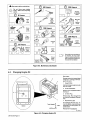
FALLING
EQUIPMENT
can
cause
serious
personal
injury
and
equipment
damage.
Lift
Unit
at
handles
on
ends
of
base.
Have
two
persons
of
adequate
strength
lift
unit.
Move
unit
with
hand
cart
or
similar
device
of
adequate
capacity.
It
using
a
fork
lift
vehicle,
secure
unit
on
a
proper
skid
before
transporting.
rwarnl.1
12/91
Keep
unit
level
tilting
can
cause
fuel
and
oil
leaks
and
possible
fire
or
engine
damage.
2
2
1
18
in
(457
mm)
Open
Space
On
All
Sides
2
Lifting
Handles
Lift
unit
with
hands
positioned
in
centerof
handles.
Obtain
help
to
lift
and
transport
unit.
3
Exhaust
Outlet
Keep
flammables
away
from
ex
haust
outlet.
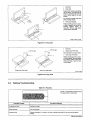
Figure
3-1.
Location
And
Movement
Of
The
Welding
Generator
5T-161
4771
ST-151
556/
Ref.
5T.161
478
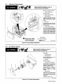
~<
Inches
Millimeters
A
B
C
19
14-5/8
28-3/4
483
371
730
C
>.-.~<
Figure
3-2.
Overall
Dimensions
OM-160
518
Page
4

Page is loading ...
Page is loading ...
Page is loading ...
Page is loading ...
Page is loading ...
Page is loading ...
Page is loading ...
Page is loading ...
Page is loading ...
Page is loading ...
Page is loading ...
Page is loading ...
Page is loading ...
Page is loading ...
Page is loading ...
Page is loading ...
Page is loading ...
Page is loading ...
Page is loading ...
Page is loading ...
Page is loading ...
Page is loading ...
Page is loading ...
Page is loading ...
Page is loading ...
Page is loading ...
Page is loading ...
Page is loading ...
Page is loading ...
Page is loading ...
Page is loading ...
Page is loading ...
Page is loading ...
Page is loading ...
Page is loading ...
Page is loading ...
Page is loading ...
Page is loading ...
Page is loading ...
Page is loading ...
Page is loading ...
Page is loading ...
Page is loading ...
Page is loading ...
Page is loading ...
Page is loading ...
Page is loading ...
Page is loading ...
Page is loading ...
Page is loading ...
Page is loading ...
Page is loading ...
Page is loading ...
Page is loading ...
Page is loading ...
Page is loading ...
-
 1
1
-
 2
2
-
 3
3
-
 4
4
-
 5
5
-
 6
6
-
 7
7
-
 8
8
-
 9
9
-
 10
10
-
 11
11
-
 12
12
-
 13
13
-
 14
14
-
 15
15
-
 16
16
-
 17
17
-
 18
18
-
 19
19
-
 20
20
-
 21
21
-
 22
22
-
 23
23
-
 24
24
-
 25
25
-
 26
26
-
 27
27
-
 28
28
-
 29
29
-
 30
30
-
 31
31
-
 32
32
-
 33
33
-
 34
34
-
 35
35
-
 36
36
-
 37
37
-
 38
38
-
 39
39
-
 40
40
-
 41
41
-
 42
42
-
 43
43
-
 44
44
-
 45
45
-
 46
46
-
 47
47
-
 48
48
-
 49
49
-
 50
50
-
 51
51
-
 52
52
-
 53
53
-
 54
54
-
 55
55
-
 56
56
-
 57
57
-
 58
58
-
 59
59
-
 60
60
-
 61
61
-
 62
62
-
 63
63
-
 64
64
-
 65
65
-
 66
66
-
 67
67
-
 68
68
-
 69
69
-
 70
70
-
 71
71
-
 72
72
-
 73
73
-
 74
74
-
 75
75
-
 76
76


Miller KD398640 User manual
- Category
- Welding System
- Type
- User manual
Ask a question and I''ll find the answer in the document
Finding information in a document is now easier with AI
Related papers
Other documents
-
Cebora 1614 Dallas 60 - 65 User manual
-
HobartWelders CHAMPION 10,000 KOHLER Owner's manual
-
ESAB Installation Instructions for Engine Protection Shutdown Kit Installation guide
-
MINOURA SGL-300S Instructions Manual
-
Draper Forestry Helmet Operating instructions
-
 King Tony 9CCF41AA-B User manual
-
Hobart Welding Products 205 AC User manual
-
 Miller Camera Support DS5 User manual
-
Danfoss VLT Soft Starter MCD 500 Operating instructions
-

