
S_EA/ S
OWNER'S
MANUAL
MODEL NO.
987.799601
Caution:
Read and Follow
All Safety Rules
and Instructions
Before Operating
This Equipment.
®
5 Horsepower
CHIPPER/VAC
with Wheel Adjusters
• Assembly
• Operation
• Customer Responsibilities
• Service and Adjustment
• Repair Parts
Sears, Roebuck and Co., Hoffman Estates, IL 60179 U.S.A.
FORM 1902963 (11/94)

SAFETY RULES
,_ CAUTION: ALWAYS DISCONNECT SPARK PLUG WIRE AND PLACE WIRE WHERE IT CAN- _tk
NOT CONTACT SPARK PLUG TO PREVENT ACCIDENTAL STARTING WHEN SETTING UP,
TRANSPORTING, ADJUSTING, OR MAKING REPAIRS.
IMPORTANT
YOUR UNIT IS EQUIPPED WITH A SAFETY INTERLOCK SYSTEM TO MINIMIZE INJURY. DO NOT ATTEMPT TO
DEFEAT THIS SYSTEM UNDER ANY CIRCUMSTANCES.
TRAINING:
• Read this Owner's Manual carefully before operating
this equipment. Be thoroughly familiar with the controls
and the proper use of this equipment.
• Never allow children or untrained adults to operate this
equipment
• Keep the area of operation clear of all persons, particu-
larly sin!I1 children, and pets. Keep bystanders at least
25 feet away from the area of operation.
= Familiarize yourself with all of the safety and operating
decals on this equipment and on any of its attachments
or accessories°
• Do not run engine in an enclosed area. Engine exhaust
contains carbon monoxide gas, a deadly poison that is
odorless, colorless, and tastetess_ Do not operate this
equipment near buildings, windows, or air conditioners
o Do not allow hands or any other part of the body or
clothing inside the vacuum inlet, chipper chute, dis-
charge opening, blower deflector, or near any moving
part° Cutting blades begin to rotate when engine starts
and slow down gradually after engine is shut off°
• Before inspecting or servicing any part of the equip-
ment, stop the engine and make sure that all moving
parts have come to a complete stop Disconnect the
spark plug wire and secure it away from the spark plug..
Be aware that rotating blades slow down gradually after
engine is shut off_
• Do not operate this equipment if you are under the influ-
ence of alcohol, medication, or when tired or ill.
PREPARATION:
° Always wear approved safety goggles (provided)
when operating this equipment. The operation of
any powered machine can result in foreign objects
being thrown by high-speed rotating parts.
• Do not wear loose-fitting clothing or jewelry that can get
drawn into the vacuum inlet or chipper chute, or that
can get caught by moving parts_
• Do not operate this equipment unless the collection bag
or blower deflector is installed.
= Do not process material through chipper chute when
equipment ison uneven ground.
= Before starting engine, check that all screws, nuts,
bolts, and other fasteners are properly secured°
Replace any damaged or unreadable warning and oper-
ating decals_
° Wear work gloves, sturdy footwear, and hearing protec-
tion when operating this equipment.
° Use extra,care when handling gasoline and other fuels.
Gasoline and its vapors are highly flammable and
explosive.. To help prevent a fire or explosion:
a. Use an approved fuel container.
b. Never add fuel to a running or a hot engine
c. Keep matches, smoking materials, open flames, and
sparks away from the fuel tank and fuel container.
d. Fill the fuel tank outdoors and with extreme care.
Never fill fuel tank indoors.
e. Replace the caps on the fuel tank and fuel container
and clean up spilled fuel before starting engine. Gas
cap shall never be removed or fuel added while
engine is running.
° Leave 1/2 inch air space at top of fuel tank to alloN for
expansion of fuel.
o Do not store the machine or fue! container where there
is an open flame or spark, or where ignition sources
such as hot water and space heaters, furnaces, clothes
dryers, stoves, or electric motors are present.
/
,_ LOOK FOR THIS SYMBOL TO POINT OUT IMPORTANT SAFETY PRECAUTIONS. |
IT MEANS - ATTENTION!!! BECOME ALERT!!! YOUR SAFETY IS INVOLVED.
J

OPERATION:
• Before starting this equipment, make certain that the
chipper chute, vacuum inlet, discharge opening, and
blower deflector are empty. Disconnect spark plug wire
before making these check&
* Never carry passengers on this equipment. They could
fall off and be seriously injured, or they could interfere
with safe operation.
• Do not allow hands or any other part of the body or
clothing inside the vacuum inlet, chipper chute, dis-
charge opening, blower deflector, or near any moving
part.
• Before vacuuming, inspect the area where the equip-
ment is to be used and remove all metal, bottles, cans,
or other foreign objects.
• Do not vacuum any burning or smoldering materials
such as cigars, cigarettes, ashes, or cinders.
• When vacuuming or chipping, be extremely careful that
pieces of metal, rocks, bottles, cans, or other foreign
objects are not included.
° Do not use vacuum or blower on areas that have been
recently treated with fertilizers, pesticides, or herbicides..
Follow chemical manufacturer's safety instructions
regarding contact with treated areas..
• Do not vacuum flammable iiquids such as gasoline,
kerosene, diesel fue!, paint thinner, etc.
• If equipment strikes any foreign object or starts making
an unusual noise or vibration, immediately shut off
engine and allow all moving parts to come to a com-
plete stop Disconnect the spark plug wire and secure it
away from the spark plug Then take the following
steps:
ao inspect for damage.
b, Replace or repair any damaged parts..
c. Check for and tighten any loose parts.
° If equipment jams or becomes clogged, immediately
shut off the engine and allow all moving parts to come
to a complete stop. Disconnect the spark plug wire
and secure it away from the spark plug. Use only a
wooden stick to clear away debris..
° Before adding or changing any attachments or before
switching between vacuum and blower operation stop
the engine and allow all moving parts to come to a com-
plete stop. Disconnect the spark plug wire and secure it
away from the spark plug. ........
• Keep atl guards, covers, and shields in place and in
good working condition
• Always stand clear of discharge area when operating
equipment with blower deflector instaliedo Material exits
at a high speed from the blower deflector..
• Do not operate the chipper with the blower deflector
installed
o
Do not operate the chipper if the chipper chute flap is
damaged or missing
Keep your face and body safely away from the chipper
chute When chipping, stand on either side of chute
and keep arms perpendicular (at a 900 angle) to chute
inlet.
Do not overreach when feeding material into the chip-
per chute, Keep proper balance and footing at all
times.
Check collection bag frequently for deterioration or wear
and replace worn bags. Use only original equipment
replacement bags Bags manufactured by others could
present a safety hazard
Before removing and installing collection bag, stop the
engine and allow al( moving parts to come to a com-
plete stop Disconnect the spark plug wire and secure it
away from the spark plug
Empty the collection bag after each use. Decomposing
debris could generate enough heat to catch fire
Exercise extreme caution on slopes and avoid exces-
sively steep slopes..
Never operate this equipment on a slippery surface.
Look behind and use care when operating in reverse.
Do not allow any part of the engine, especially around
the cooling fins and muffler to become clogged with
leaves, oil, grease, or any other combustible material
Watch for traffic when operating near, or when crossing
roadways.
Never leave the equipment unattended when the
engine is running.. Stop the engine, disconnect spark
plug wire, and secure it away from the spark plug
before leaving the equipment
• Use only attachments and accessories that are
approved for use with this equipment..
• Operate equipment only in daylight or in good artificial
fighL
• Do not tamper with the engine governor settings The
governor controls the maximum safe operating speed
and protects the engine and atl moving parts from dam-
age caused by excessive speed. Request help at the
nearest Sears service location if a problem exists.
m
This equipment is provided with a safety interlock sys-
tem which prevents the engine from starting unless the
collection bag or blower deflector is installed.. The sys-
tem is also designed to shut off the engine if the opera-
tor attempts to remove the collection bag or blower
deflector while the engine is running.. Never attempt to
disconnect or otherwise defeat the purpose of this sys-
tem if the interlock fails to operate properly, shut off
the engine and do not operate this equipment until the
system is repaired and is functioning properly.

MAINTENANCE AND STORAGE:
• When equipment is stopped for servicing, inspection,
storage, or to change an attachment or accessory,
make sure the spark ptug wire is disconnected from the
spark plug Allow the engine to cool before making any
inspections, adjustments, etc
• Maintain equipment and atl attachments and acces-
sories in safe working condition°
• Never perform any maintenance while engine is running
or when spark plug wire is connected to spark plug,
except where specifically instructedto do so_
• Never store this equipment with fuel in the fuel tank
inside a building where fumes may reach an open flame
or spark, or where ignition sources are present such as
hot water and space heaters, furnaces, clothes dryers,
stoves, electric motors, etco
• Allow engine to cool before storing in any enclosure.
• Store gasoline in a cool, well-ventilated area, safely
away from any spark- or flame-producing equipment.
Store gasoline in an approved container, safely out of
the reach of children.
. Use only original equipment replacement parts° Parts
manufactured by others could present a safety hazard
even though they may fit on this equipmenL
• Store this equipment where children will not have
access. Always disconnect the spark plug wire from the
spark plug to prevent accidental starting_
• Check collection bag frequently for deterioration or wear
and replace worn bags. Use only original equipment
replacement bags. Bags manufactured by ethers could
present a safety hazard.
• Refer to "Off Season Storage" in this Manual for impor-
tant storage instructions ifequipment is to be stored for
an extended period.
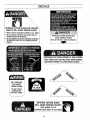
SAFETY DECALS:
• Make certain that all safety decals on this equipment are
kept clean and in good condition. The decals are shown
on Page 35 of this Manual

CONGRATULATIONSonyourpurchaseofaSears
CraftsmanChipperNac.ithasbeendesigned,
engineered and manufactured to give you the best
possible dependability and performance.
Should you experience any problems you cannot easily
remedy, please contact your nearest Sears Service
Center or Retail Store. We have competent, well-trained
technicians and the proper tools to service or repair this
machine.
Please read and keep this Manual The instructions will
help you assemble, operate, and maintain your machine
properly° Always observe the SAFETY RULES
MODEL NUMBER 987_799601
SERIAL NUMBER:
DATE OF PURCHASE:
THE MODEL AND SERIAL NUMBER DECAL IS
LOCATED ON THE LEFT SIDE OF THE ENGINE
MOUNTING PLATFORM.
YOU SHOULD RECORD BOTH THE SERIAL
NUMBER AND THE DATE OF PURCHASE KEEP
THEM IN A SAFE PLACE FOR FUTURE
REFERENCE.
MAINTENANCE AGREEMENT
A Sears maintenance agreement isavailable on this
chipper/vac Contact your nearest Sears store for details.
CUSTOMER RESPONSIBILITIES
* Read and observe the safety rules
* Foltow a regular schedule in maintaining, caring for and
using your chipper/vac,.
o Follow the instructions under "Customer
Responsibilities" and "Storage" sections of this manual.
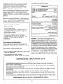
PRODUCT SPECIFICATIONS
Chipper/Vac
Weight 65 lbs°
Length with Handlebars Extended 48 in.
Length with Handlebars Folded 28 in.
Width 22 in.
Engine
Engine 5 HP Tecumseh Model TVS ! 15
Engine Type Vertical Crankshaft
Air-Cooled
Four Cycle
Engine Displacement ! 1.5 cu in.
Gasoline Capacity 1-1/4 qts.
Oil (21 ounce capacity) Above 32 ° F: SAE 30
Below 32 ° F: SAE 5W30
Spark Plug (gap O.030qn,) Champion J19LM
Autolite 458, or equivalent.
In Canada, replace with
resistor spark plug,
Valve Clearance Intake: .006 in
Exhaust: .,006 in
WARNING: This chipper/vac is equipped with an
internal combustion engine and should not be used on or
near any unimproved forest-covered, brush-covered or
grass-covered land unless the engine's exhaust system
is equipped with a spark arrester meeting applicable local
or state laws (if any). If a spark arrester is used, it should
be maintained in effective working order by the operator
In the state of California the above is required by law
(Section 4442 of the California Public Resources Code).
Other states may have similar laws Federal laws apply
on federal lands A spark arrester for the muffler is
available through your nearest Sears authorized service
center. See the REPAIR PARTS section of this manual.
LIMITED ONE YEAR WARRANTY
For One Year from date of purchase, when this Chipper/Vac is maintained, lubricated, and tuned up according
to the operating and maintenance instructions in the Owner's Manual, Sears will repair free of charge any
defect in material or workmanship°
This warranty excludes the collection bag, spark plug, air cleaner, and chipper blade which are expendable
parts and become worn during normal User
if this Chipper/Vac is used for commercial or rental purposes, this warranty applies for only 30 days from the
date of purchase
WARRANTY SERVICE IS AVAILABLE BY CONTACTING THE NEAREST SEARS SERVICE
CENTER/DEPARTMENT iN THE UNITED STATES.. This warranty applies only while this product is in use in
the United States..
This warranty gives you specific legal rights, and you may also have other rights which vary from state to state
SEARS, ROEBUCK AND CO. D/817WA - HOFFMAN ESTATES, IL 60179

TABLE OF CONTENTS
SAFETY RULES ................................................... 2
PRODUCT SPECIFICATIONS .............................. 5
WARRANTY .......................................................... 5
CHIPPER/VAC ATTACHMENTS .......................... 7
ASSEMBLY ........................................................... 8
OPERATION ....................................................... 17
CUSTOMER RESPONSIBILITIES ..................... 27
SERVICE AND ADJUSTMENTS ........................ 30
STORAGE ........................................................... 32
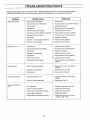
TROUBLESHOOTING ........................................ 33
DECALS .............................................................. 35
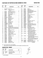
REPAIR PARTS - CHIPPERNAC ....................... 36
REPAIR PARTS - ENGINE ................................. 38
PARTS ORDERING/SERVICE ........... Back Cover
iNDEX
A
Air Filter ......................... 28
Assembly ....................... 8-16
B
Baffle Plate ................... 16
Blade, Chipper ................... 30
Blower Deflector ............. 13
Blower Operation ................ 24
Bolts, Torque ................ 31
C
Chipper
Chute Location ............... 17
Cutting Blade ................. 30-31
Operating Tips ................ 25
Operation ....................... 25
Clearing Jams and Clogs ....... 26
Collection Bag, Install ........... 10
Collection Bag, Remove ....... 12
Control Lever, Engine ........... 17
Cooling System, Cleaning ....... 28
Customer Responsibilities ..... 27
Cutting Blade, Chipper ....... 30-31
!]
Decals .................... 35
Engine
Air Filter ..................... 28
Control Lever ............... 17
Cooling System ............ 28
Fuel ............................... 19
Ignition .................. 29
Oil .............................. 27
Operation .............. 19-20
Primer ................................ 20
Spark Arrester ............. 28
Spark Plug ..................... 29
6
Gasoline
Adding ....................... 19
Specifications ................... 18
It
Handlebars ................... 8
I
Ignition System ....................... 29
Installing Shredder Screen ..... 1l
J
Jams and Clogs .............. 26
L
Location of Controls ................ 17
Lubrication .................. 29
M
Materials to Avoid ................. 21
Model/Serial Number ........... 5
0
Oil .............................. 5, 18
Off-Season Storage ........... 32
Operation, Safety ................ 3
P
Parts List........................ 36-40
Preparation, Safety ............ 2
Primer ..................... !7, 20
R
Recoil Starter Rope .......... 17, 20
Removing Shredder Screen ..... 11
Replacing Chipper Cutting
Blade .................... 30-31
Safety Rules ....................... 2-4
Safety Decals ................ 35
Safety Interlock ............... 8
Service, Engine ............ 27-29
Service Recommendation
Checklist ......................... 27
Shredder Screen .............. t 1
Spark Arrester ........................ 28
Spark Plug ..................... 29
Starter Rope ................. 17, 20
Storage
Safety ............................... 4
Off-Season ................ 32
T
Tips & Hints
Chipper Operation .......... 25
Vacuum Hose Operation ....... 23
Walk-Behind Vacuuming ........ 22
Torque Chart ................. 31
Training, Safety .................... 2
Troubleshooting ............ 33-34
U
Unpacking ..................... 8
V
Vacuum Hose
Installation ................. 14
Operation ................... 23
Vacuum Inlet
Cap ............................ 17
Vacuuming
Assembly for ................... 10
Handlebar Position for ........ 8
Operation ...................... 22
Vacuuming and Chipping
Guide ......................... 21

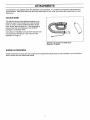
ATTACHMENTS
This attachment was available when the chipper/vac was purchased° It is available at most Sears retail outlets and
service centers. Most Sears stores can also order repair parts for you, when you provide the model number of your
chipper/vac.
VACUUM HOSE
The optional vacuum hose attachment allows you to
extend the reach of the machine by 10 feet to easily
reach in, around, under and behind bushes, shrubs,
trees, fences, lawn furniture, etc. If you purchased a
vacuum hose with the chipper/vac, you will find it
packaged in a separate carton°
Instructions for insta!iation and use of the vacuum hose
are presented in this Manual. See "Vacuum Hose
Operation" on Page t4.
Optional vacuum hose and baffle plate,
(Stock No. 71-85689)
ENGINE ACCESSORIES
Engine accessories such as gas cans, engine oil, and replacement spark plugs are also available at your local Sears
service center and most Sears retail outlets.

ASSEMBLY
Read these instructions in their entirety before you attempt to assemble your new chipper/vaco Your new chipper/vac
has been completely assembled at the factory, except for the items shown in Figure 1.. To ensure proper operation of
your chipper/vac, all nuts and bolts must be securely tightened when changing the configuration of the machine Use
the correct tools as necessary to ensure proper tightness.
UNPACKING INSTRUCTIONS (see Figure 1)
1, The following items are contained in the shipping A
carton and shown in Figure 1: _ B C
(A) Chipper/Vac //
(B) Safety Goggles __P'
(C) Blower Deflector
(D) Collection Bag J
2. Check for missing or damaged parts.. If any parts are
missing or damaged, contact your local Sears service
center or Sears retail outlet for assistance
IMPORTANT: MOTOR oIL AND GASOLINE MUST BE
ADDED TO THE ENGINE BEFORE THE ENGINE IS
STARTED_ THE PROCEDURES FOR ADDING
MOTOR OIL AND GASOLINE ARE ON PAGES 18
AND 19.
NOTE: All references to the front, rear, left and right of
the machine are determined as follows:
The inlet cap for the optional vacuum hose is located on
the front of the machine. The discharge opening is at
the rear The left and right sides are determined by
standing at the rear of the machine when the handlebars
are in the "vacuum" position
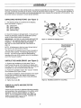
UNFOLD THE HANDLEBARS (see Figure 2)
1, Squeeze the handlebar end (with decal "Push in
Here") toward the center of the machine to release end
from the notch in the mounting bracket (C) and swing the
handlebars up over the machine toward the rear.
2. Position the handlebar ends in the "vacuum" notches
of the brackets (D in Figure 2 inset).
3o Unfold the handlebars until the channels on the upper
left and right handlebars are aligned with the lower
handlebars (A) If necessary, loosen knobs (B) before
unfolding handlebars.
4_ Tighten the knobs (B)
Figure 1: Contents of shipping carton.
ExtendHandlebarsin
VacuumPosition
A
\
Handlebars
Folded
Figure 2: Handlebar position for vacuuming.
CHECK ALL NUTS AND BOLTS FOR
TIGHTNESS
Check all nuts and bolts for tightness following assembly
and according to the schedule given in the section which
describes "Customer Responsibilities" on Page 27.
NOTE: Do not overtighten the bolts which attach the
engine mounting plate to the housing DAMAGE TO
THE HOUSING COULD RESULT

ASSEMBLY
ASSEMBLY CONFIGURATIONS
Your machine has been partially assembled at the
factory. The remaining assembly steps should be done
on a clean, level surface, Choose the mode of operation
from the pictures below and then go to the page for
assembly of the chipper/vac in the desired configuration..
CAUTION
To preventpersonalinjuryor propertydamage, donot
connectthe spark plug or start the engine until all
assemblystepsare complete and you have read and
understoodthe safety and operating instructionsin
this Manual
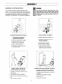
Walk-behind vacuuming - see Page t0
WALK-BEHIND VACUUMING
OPERATION CHECKLIST
v" Collection bag installed and zipped
v' Baffle plate off (provided with
optiona] vacuum hose kit only)
V' Vacuum inlet cap installed
v' Handlebars positioned toward the
rear of the machine
Blower operation, see Page 12
BLOWER OPERATION CHECKLIST
v' Handlebars positioned toward the
front of the machine.
v" Collection bag removed
v" Blower deflector installed.
v' Vacuum inlet cap installed..
v' Baffle plate off (provided with
optional vacuum hose kit only)
Using the chipper, see Page 10
CHIPPER OPERATION CHECKLIST
v' Handlebars positioned toward the rear of
the machine,
v" Collection bag installed and zipped
v" B{ower deflector and baffle plate (optional)
off
i/" Vacuum inlet cap installed.
Using the vacuum hose (optional) - see Page 14
VACUUM HOSE OPERATION CHECKLIST
v' Handlebars positioned toward the rear of the
machine
Collection bag installed and zipped
v" Baffle plate on
v' Vacuum hose installed

ASSEMBLY
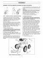
ASSEMBLY FOR WALK-BEHIND VACUUMING OR USING THE CHIPPER
STEP 1: REMOVE OR INSTALL SHREDDER SCREEN
A shredder screen (A, Figure 3) is factoryqnstalied
inside the processing chamber, Vacuumed or chipped
material passes through the slots in the screen before it
is discharged, The screen produces up to an 8:1
reduction of material.
The screen is designed for use only with dry materials
Before processing damp materials, remove the screen to
reduce clogging and to improve air flow inside the
processing chamber. Before chipping a large number of
branches, remove the shredder screen for faster
discharge of the chips.
To Remove Shredder Screen:
1. Stop the engine, disconnect the spark plug wire
from the spark plug, and make sure that all moving
parts have come to a complete stop.
2. To remove rear rod (B, Figure 3), remove the
collection bag or the blower deflector (if installed).. Then,
remove the hair pin clip (D) and pull the rod out through
the bottom of the deck
3. Use sturdy supports to prop up the right side of the
machine a few inches Then, remove the hair pin clip
(D) and pull the front rod (C) out through the bottom of
the deck.
4. Pull the screen (A) out of the discharge opening.. Re-
install the rods and hair pin clips on the screen for safe-
keeping.
IMPORTANT: THE HAIR PIN CLIPS SUPPLIED WITH
THE SCREEN ARE THE ONLY STYLE FASTENERS
THAT SHOULD BE USED° DO NOT USE
SUBSTITUTES OR FAILURE OF EQUIPMENT OR
PERSONAL INJURY COULD RESULT.
5. Remove supports from beneath machine_
To Install Shredder Screen:
1o Stop the engine, disconnect the spark plug wire
from the spark plug, and make sure that all moving
parts have come to a complete stop.
2. Remove the collection bag. Remove the rods and
hair pin clips which were stored on the shredder screen.
Insert the screen (A) into the processing chamber with
the flat, angled end facing to the rear and the curve in
the screen facing to the righL See Figure 3_ Align
mounting holes in screen with the holes in deck..
3. Using sturdy supports, prop up the right side of the
machine a few inches. Insert front rod (C) up through
bottom of deck, into screen mounting hole, and out
through the top of the deck. Test that the rod is through
the screen by pulling on the screen - the screen should
not move. Secure rod with hair pin clip (D).
4. Insert rear rod (B) up through bottom of deck, into the
screen mounting hole, and out through the top of the
deck.. Make sure that the rod is in the screen by trying to
move the screen from side to side Secure the rod with
the hair pin clip (D)
5. Re-install the collection bag_
Figure 3: Shredder screen installation.
10

ASSEMBLY
CAUTION
STEP 2: INSTALL COLLECTION BAG
For walk-behind vacuuming or using the chipper, install
the collection bag as described below.
1. Stop the engine, disconnect the spark plug wire
from the spark plug, and make sure that all moving
parts have come to a complete stop.
2, Make sure the bag (A in Figure 4) is zipped
3. Place the collection bag straps over the handlebars,
4. Line up the tabs on the bag inlet adapter (B) with the
slots in the discharge opening (C) and slide the bag inlet
adapter down all the way into the slots. Turn the
retaining knob (F) until the tab on the knob drops into the
slot on the top of the bag inlet adapter
Figure 4: Install collection bag.
NOTE: Thei'od (D) on the inlet adapter is part of the
machine's safety interlock system Make sure that the
rod fits securely in the slot in the safety interlockswitch (E).
BAG MAINTENANCE TIP: Keep the bag clean by
occasionally washing it (by hand) with mild soap and
water A clean bag improves air flow and results in
better vacuuming performance, Do not wash the bag in
an automatic washer Do not use a cleaner which
contains bleach Allow the bag to dry thoroughly before
storing,
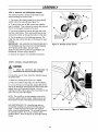
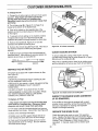
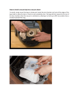
STEP 3: ADJUST THE VACUUM INLET HEIGHT
The vacuum inlet height can be adjusted to six different
settings in approximately 1/2" increments. These
settings allow inlet suction to be adjusted for varying
needs, For example, when vacuuming deep layers of
leaves, adjust the vacuum inlet height at the front of the
machine to its highest setting as described below (see
Figure 5):
1. Stop the engine, disconnect the spark plug wire
from the spark plug, and make sure that all moving
parts have come to a complete stop,
2. Squeeze the adjuster lever (A in Figure 5) toward the
wheel to disengage the adjuster pin from the hole in the
height adjuster bracket,
3. Rotate the adjuster lever toward the rear (discharge
opening) of the machine to raise the height and then
release the adjuster lever so that the adjuster pin
engages the selected hole in the bracket, Rotate the
lever in the opposite direction to lower the inlet height.
4. Be sure that both adjuster levers are adjusted to the
same height
B
Figure 5: Vacuum Height Adjustment Lever and Inlet Cap.
STEP 4: INSTALL VACUUM INLET CAP
1. Postion the inlet cap (B, Figure 5) so that the bar on
the cap is aligned with the arrow at the REMOVE
position.
-2. Twist the cap 1/4 turn clockwise which will secure the
cap in place,
11

ASSEMBLY
1,1,,, ,,,,,,,,,,,,,,,, = L = J =LJJui,,,Jiu,i,u,,, ,,,,,,,,i,
ASSEMBLY FOR BLOWER OPERATION
STEP 2: ADJUST HANDLEBARS
If the handlebars are in the vacuum position, they must
be adjusted to the "blower" position for blower operation.
1. Squeeze the handlebar end (see decal "Push in
Here") toward the center of the machine and swing the
handlebars over to the front of the machine,
2. Release the handlebars ends in the "blower" notches
(A), See Figure 7.
IMPORTANT: DO NOT USE THE CHIPPER IF THE
MACHINE IS SET UP FOR BLOWER OPERATION..
STEP 1: REMOVE 'THE COLLECTION BAG (IF
INSTALLED)
1o Stop the engine, disconnect the spark plug wire
from the spark p/ug, and make sure that all moving
parts have come to a complete stop.
2_ Pull and then turn the retaining knob (F in Figure 6)
so that it clears the edge of the bag inlet adapter (B) and
the tab rests on the upper housing_ Grasp the pull strap
and slide the bag inlet adapter (B) out of the slots in the
discharge opening (C).
3. Hold the collection bag (A) with the inlet opening
upright so that material does not fall out, and slide the
straps off the handlebars
4, Unzip the collection bag and empty it by shaking the
bag gently to remove all debris
\ \
\
A
Figure 7: Adjust handlebars to "blower" position_
STEP 3: ADJUST THE VACUUM INLET HEIGHT
For best results, adjust the vacuum inlet to its highest
position for operating the blower, Instructions for making
this adjustment are provided on Page 11.
Figure 6: Remove collection bag,
12

ASSEMBLY
STEP 4: REMOVE THE SHREDDER SCREEN
For maximum air flow, remove the shredder screen
before insta!iing the blower deflector
1. The screen (A) is held in place by two long rods (B
and C) and hair pin clips (D), See Figure 8,
2. To remove the rear rod (B), remove the hair pin clip
(D) and pull the rod out through the bottom of the deck°
3. Use sturdy supports to prop up the right side of the
machine a few inches,. Then, remove the hair pin clip
and pull the rod (C) out through the bottom of the deck,
4. Pull screen (A) out of the discharge opening, Re-
install the rods and hair pin clips on the screen for safe-
keeping_
IMPORTANT: THE HAIR PIN CLIPS SUPPLIED WITH
THE SCREEN ARE THE ONLY STYLE FASTENERS
THAT SHOULD BE USED, DO NOT USE
SUBSTITUTES OR FAILURE OF EQUIPMENT OR
PERSONAL iNJURY COULD RESULT,
5. Remove the supports from beneath unit
STEP 5: INSTALL BLOWER DEFLECTOR
Position the tabs on the sides of the blower deflector (A
in Figure 9) into the slots in the discharge opening (B)
and slide the blower deflector down all the way into the
slots, Turn retaining knob (D) until the tab on the knob
drops into the slot on the blower deflector° (Reverse this
procedure when removing the blower deflector,)
NOTE: The rod (C) on the blower deflector is part of the
machine's safety interlock system, Make sure that the
rod fits securely in the slot in the safety interlock switch
(E).
STEP 6: INSTALL VACUUM INLET CAP
1. Postion the inlet cap (A, Figure 10) so that the bar on
the cap is aligned with the arrow at the REMOVE
position,
2. Twist the cap 1/4 turn clockwise which will secure the
cap in place.,
IMPORTANT: THE VACUUM INLET CAP MUST BE
iNSTALLED DURING BLOWER OPERATION,
Figure 8: Shredder screen removal
Figure 9: Install blower deflector,.
D
A
Figure 10: Vacuum Inlet Cap installed,
13

ASSEMBLY
ASSEMBLY FOR OPTIONAL VACUUM
HOSE OPERATION
NOTE: The optional Vacuum Hose is designed for
stationary vacuuming operation only,
STEP 1: MOVE HANDLEBARS TO VACUUMING
POSITION
1. Stop the engine, disconnect the spark plug wire
from the spark plug, and make sure that all moving
parts have come to a complete stop,
2. Squeeze the handlebar end (A in Figure 11 insetwith
decal "Push in Here") toward the center of the machine
to release end from the notch in the mounting bracket
and swing the handlebars up over the machine toward
the rear
3. Position the handlebar ends in the "vacuum" notches
of the brackets (B in Figure 11 inset) r
STEP 2: REMOVE BLOWER DEFLECTOR (IF
INSTALLED)
Turn retaining knob (D in Figure 12) until the tab on the
knob is out of the slot in the blower deflector,, Pull the
sides of the blower deflector (A in Figure 12) out of the
slots in the discharge opening (B) and slide the blower
deflector off the machine.
Handlebarsin Vacuum
Position
Figure 11: Handlebar position for vacuuming.
A
Figure 12: Remove blower deflector_
14

ASSEMBLY
STEP 3: REMOVE THE SHREDDER SCREEN
For maximum air flow, remove the shredder screen
before installing the vacuum hose.,
t. The screen (A) isheld in place by two long rods (B
and C) and hair pin clips (D) (see Figure 13).
2. To remove the rear rod (B), remove the collection
bag (if installed). Then, remove the hair pin clip and pull
the rod out through the bottom of the deck,
3. Use sturdy supports to prop up the right side of the
machine a few inches Then, remove the hair pin clip
and pull the rod (C) out through the bottom of the deck,
4. Pull the screen out of the discharge opening_ Re-
install the rods and hair pin clips on the screen for safe-
keeping.
IMPORTANT: THE HAIR PiN CLIPS SUPPLIED WITH
THE SCREEN ARE THE ONLY STYLE FASTENERS
THAT SHOULD BE USED DO NOT USE
SUBSTITUTES OR FAILURE OF EQUIPMENT OR
PERSONAL INJURY COULD RESULT.
5. Remove the supports from beneath the machine.
A
Figure t3: Shredder screen removal
STEP 4: INSTALL COLLECTION BAG
CAUTiOR
• Check the collection bag frequently for
deteriorationandwear and replacewornhags.
For using the vacuum hose, install the collection bag as
described below.
1. Make sure the bag (A in Figure 14) is zipped
2. Place the collection bag straps over the handlebars,
3. Line up the tabs on the bag inlet adapter (B) with the
slots in the discharge opening (C) and slide the bag inlet
adapter down all the way into the slots, Turn the
retaining knob (F) until the tab on the knob drops into the
slot on the top of the inlet adapter,,
NOTE: The rod (D) on the inlet adapter is part of the
machine's safety interlock system, Make sure the rod
fits securely in the slot in the safety interlock switch (E).
BAG MAINTENANCE TIP: Keep the bag clean by
occasionally washing it (by hand) with mild soap and
water. A ctean bag improves air flow and results in
better vacuuming performance, Do not wash the bag in
an automatic washer Do not use a cleaner which
contains bleach, Allow the bag to dry thoroughly before
storing.
C
Figure 14: Install collection bag°
D
E
15

ASSEMBLY
H, ,,i,llllllliH i i
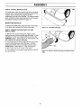
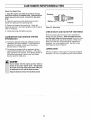
STEP 5: INSTALL BAFFLE PLATE
The baffle plate, which is included only with the optional
vacuum hose, concentrates the suctioning power of the
machine intothe hose by blocking the air flow
underneath the front of the machine. To instali the baffle
plate, position the plate underneath the front of the deck
and snap it into place as shown in Figure 15.
Baffle Plate Removal
To remove the baffle plate, grasp the tabs on each side
of the plate, press outward, and remove the plate
STEP 6: REMOVE VACUUM INLET CAP AND
INSTALL HOSE
1_ Remove the vacuum inlet cap (A, Figure 16) by
twisting the cap counterclockwise approximately I/4 turn
until the bar on the cap isaligned with the arrow at the
REMOVE position_ Lift the cap off the inlet opening. Do
not misplace the vacuum inlet cap.
2. Line up the tabs on the hose (B) with the slots in the
vacuum inlet opening and insert the hose.. Turn the
hose approximately t/4 turn clockwise until it is in the
LOCK position See Figure 16. (The hose support
handle should now be on the top of the hose.)
3. The machine is now properly assembled for use with
the vacuum hose1
Figure 15: Install the baffle plate.
Figure 16: Remove vacuum inlet cap and Install vacuum
hose,
16

OPERATION
KNOW YOUR CHIPPERiVAC
READ THIS OWNER'S MANUAL AND SAFETY RULES
BEFORE OPERATING YOUR CHIPPERNACo Figure
17 identifies the following key features and controls on
your machine:
(A) COLLECTION BAG: Used to collect material
resulting from vacuuming or chipping operation,
(B) ENGINE CONTROL LEVER: Used to control the
speed of the engine
(C) ENGINE PRIMER: Provides additional fuel from the
carburetor to the cylinder for use when starting a cold
engine,,
(D) AIR CLEANER: Filters dirt which could damage
engine parts,
(E) CHIPPER CHUTE: Used to process small
branches.
(F) FUELTANK: Stores engine fuel
(G) RECOIL STARTER ROPE: Used to start the
engine_
(H) BLOWER DEFLECTOR: Directs air flow when
machine is used in blower configuration.
(I) SAFETY INTERLOCK ROD: Part of the safety
interlock system which stops the engine if either the
collection bag or blower deflector is not installed.
(J) VACUUM HOSE (OPTIONAL): Used for remote
vacuuming
(K) BAFFLE PLATE: Used with optional vacuum hose°
(L) VACUUM INLET CAP: Covers vacuum hose inlet
when machine is used for walk-behind vacuming or
chipping,
(M) SPARK PLUG: Provides spark for engine ignition
(N) VACUUM HEIGHT ADJUSTMENT LEVER: Allows
adjustment of the space between the bottom of the
machine and the ground,
!,1
!
N
N
!.
Figure 17: Features and Controls,
17

OPERATION
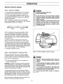
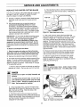
BEFORE STARTING ENGINE
STEP t: ADD OIL TO ENGINE
1, The machine was shipped without oil in the engine
The engine requires approximately 2t ounces of oil
2, Only use high quality detergent oil rated with the
APJ. service classification of "SF" or "SG" Select the
oil's SAE viscosity grade according to your expected
operating temperature:
NOTE: Change the oi! after the first two operating
hours,. See "Changing Oil" on Page 27 in the "Customer
Responsibilities" section of this Manual.
colder-_ 32°F _ warmer
5W30 SAE 30
DAHaER
RotatingCuttingBladesWill Cause
SeriousPersonalInjury!
Do not allow handsor anypart of the bodyor clothing
inside the vacuum inlet, chipper chute, discharge
opening, or blower deflector opening when the
engineis running.
Before inspecting or servicing any part of the
machine, stop the engine and make sure that all
moving parts have come to a complete stop°
Disconnectthe spark plug wire and secure it away
from the sparkplug.
NOTE: Although multi-viscosity oils (5W30, 10W30,
etc), improve starting in cold weather, these multi-
viscosity oils will result in increased oil consumption
when used above 32°F. Check your engine oil level
more frequently to avoid possible engine damage from
running low on oil,
3, With the machine on level ground, remove the
dipstick (A, Figure 18) and place it on a clean surface.
4, Using a clean funnel, slowly add oil to the dipstick
hole. While adding oil, frequently reinstall dipstick (screw
dipstick down securely) to check oil level Wipe dipstick
with a clean cloth before reinserting each time Fill to the
"FULL" mark on dipstick. DO NOT OVERFILL!
5. Reinstall the dipstick securely
A
STEP 2" ADD GASOLINE TO THE FUEL TANK
Fill the fuel tank with fresh, clean, unleaded regular
automotive gasoline. (Leaded regular and un}eaded
premium grades of gasoline are acceptable substitutes.)
Q Do not mix oil with gasoline.
Q Do not use gasoline left over from last season or
stored for long periods,,
WARNING: Experience indicates that alcohol blended
fuels (called gasohol or using ethanol or methanol) can
attract moisture which leads to separation and formation
of acids dufing storage. Acidic gas can damage the fuel
system of an engine while in storage
To avoid engine problems, the fuel system should be
emptied before storage for 30 days or longer. Drain the
gas tank, start the engine and let it run until the fuel lines
and carburetor are empty Use fresh fuel next season°
See STORAGE instructions for additional information.
Never use engine or carburetor cleaner products in the
fuel tank or permanent damage may occur.
Figure 18: Remove dipstick to add oil to engine,
DAHGER
Gasoline is highly flammable and its vapors are
explosive° To prevent personal injury or property
damage:
• Do not add fuel if the engine is runningor still hot
from recent operation. Allowthe engine tocool forat
leastthree minutes°
,* Do notfill the feel tank indoors. After filling.wipe
up any spills and move the machine away from
gasolinefumesbeforestartingtheengine.
• Do not allow openflames, matches, or smoking in
areao
18

OPERATION
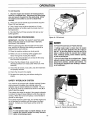
To Add Gasoline
1, Stop the engine and wait for all moving parts to
come to a complete stop. Disconnect the spark plug
wire and secure it away from the spark plug, Allow
the engine and muffler to cool for at least three
minutes,
2. Clean area around fuel fill cap and remove cap (A in
Figure 19) from fuel tank_
3. Use a clean funnel to fill the fuel tank to 1/2 inch
below the bottom of the filler neck (to provide room for
fuel expansion).
4. Re-install the fuel fitl cap securely and wipe up any
spilled gasoline.
PRE-STARTING PROCEDURES
IMPORTANT; REVIEW THE SAFETY SECTION AND
READ THIS SECTION IN ITS ENTIRETY BEFORE
STARTING THE ENGINE,
With the spark plug wire disconnected from the spark
plug, perform the following pre-starting procedures as
required before each start-up:
[] Place the machine outdoors on level ground_
[] Make sure you are wearing safety goggles (and
heavy work gloves if using the chipper),
[] Be sure that all bystanders are at least 25 feet away
from the area of operation,
[] Check that the chipper chute, vacuum inlet, or
discharge deflector are empty (after initial use of the
machine).
Q Check that all screws, nuts, bolts, and other fasteners
are properly secured_
O Check the oi! level in the engine
Q Re-attach the spark plug wire before starting the
engine,,
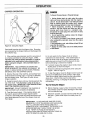
SAFETYINTERLOCK SYSTEM
Your machine is equipped with a Safety Interlock System
which prevents the engine from starting unless the
collection bag (or blower deflector) is installed. The rod
(A, Figure 20) must be positioned as shown in slot (B) in
order to start the engine..
The system also stops the engine if the operator attempts
to remove the bag or blower deflector while the engine is
running When the rod is not in place, a circuit doses to
ground out the engine
If the safety interlock system fails, shut off the engine and
do not operate the machine until the system has been
repaired, Contact your local Sears service center for
repairs,
WARNING
To avoid personalinjury or propertydamage, do not
operale this machine unless the safety interlock
systemisfunctioningproperly°
Figure
19
19: Fill fuel tank.
DANGER
To Prevent PersonalInjuryor Property Damage:
,, Cutting blades begin to rotate when the engine
starts and slow down gradually after the engine is
shut off. Do not allow handsor any otherpart ofthe
body or clothing inside the vacuum inlet, chipper
chute, dischargeopening,blower deflector opening,
or near anymoving part.
,, Do not runthe engine in an enclosedarea° Engine
exhaust contains carbon monoxide gas, a deadly
poisonthat is odorless, colorlessand tasteless. Do
not operate this equipmentnear buildings,windows,
or air conditioners.
B
Figure 20: Safety Interlock System.

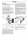
OPERATION
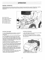
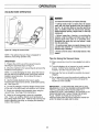
GENERAL OPERATION
Understanding how your machine works will help you achieve the best results when using the Chipper/Vac+ Read the
following explanation before using the machine and see Figure 21 which shows the internal workings of the
ChipperiVac_
(A) Chipper Chute
(B) Chipper Cutting Blade
(C) Shredder Screen
(D) Processing Chamber
(E) Fan Blade (1 of 4)
(F) Discharge Opening
F
Figure 21: Cutaway view., (Blower deflector removed for clarity,)
A
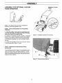
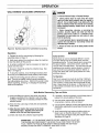
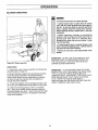
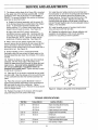
STARTING THE ENGINE
1, Put on safety goggles and work gloves, Do not wear
loose fitting clothing or jewelry that can get caught in
moving parts.
2. Move the Engine Control Lever (A, Figure 22) all the
way to the right (toward rabbit position) until it stops.,
3. When starting a cold engine, firmly push primer (B,
Figure 22) five (5) times before trying to start the engine
(This step is not required when starting an engine which
has already run for a few minutes)
4+Stand at the left front of the machine Place one foot
against left front wheel to stabilize the machine,
5+ Look behind you to make sure there are no obstacles
in the way. Grasp the Starter Rope Handle (C) and pull
handle quickly. Do not alfow starter rope to snap back.,
NOTE: In cool weather, repeat pfimimg step if
necessary, in warm weather, over priming may cause
- flooding so that the engine wilt not start, If the engine is
flooded, wait a few minutes before attempting to start it
and do not repeat the priming step.
6. Leave the Engine Control Lever at the FAST (rabbit)
setting. FAST is the recommended setting for all
vacuuming and chipping operations.
STOPPING THE ENGINE
1. Move the Engine Control Lever all the way to the left
(toward turtle position) until it stops.
2. Listen for all moving parts to come to a complete
stop There is an audible tone when the cutting blades
are slowing down.,
Figure 22: Starting and stopping the engine,
20
Page is loading ...
Page is loading ...
Page is loading ...
Page is loading ...
Page is loading ...
Page is loading ...
Page is loading ...
Page is loading ...
Page is loading ...
Page is loading ...
Page is loading ...
Page is loading ...
Page is loading ...
Page is loading ...
Page is loading ...
Page is loading ...
Page is loading ...
Page is loading ...
Page is loading ...
Page is loading ...
Page is loading ...
Page is loading ...
Page is loading ...
Page is loading ...
-
 1
1
-
 2
2
-
 3
3
-
 4
4
-
 5
5
-
 6
6
-
 7
7
-
 8
8
-
 9
9
-
 10
10
-
 11
11
-
 12
12
-
 13
13
-
 14
14
-
 15
15
-
 16
16
-
 17
17
-
 18
18
-
 19
19
-
 20
20
-
 21
21
-
 22
22
-
 23
23
-
 24
24
-
 25
25
-
 26
26
-
 27
27
-
 28
28
-
 29
29
-
 30
30
-
 31
31
-
 32
32
-
 33
33
-
 34
34
-
 35
35
-
 36
36
-
 37
37
-
 38
38
-
 39
39
-
 40
40
-
 41
41
-
 42
42
-
 43
43
-
 44
44


Craftsman 987.799601 User manual
- Category
- Garden shredders
- Type
- User manual
Ask a question and I''ll find the answer in the document
Finding information in a document is now easier with AI
Related papers
-
Sears Craftsman 247.795940 User manual
-
Craftsman 247.79962 User manual
-
-
-
-
-
-
-
-
Other documents
-
 ZVac 15pk5055cloth User guide
-
PylePro PLPTS25 Owner's manual
-
Champion Power Equipment 100137 Specification
-
MTD 24A060G099 Owner's manual
-
Patriot 5F, 6F, 8F, 10F User manual
-
 Patriot Products 10F-CSV User manual
-
Bolens Vacuum Cleaner No. 247.770550 User manual
-
-
Simplicity Vacuum Cleaner 6/25 User manual
-
Troy-Bilt 24A070J766 User manual

