
B1.ACPowerSocket
B2.SerialPort(Optional)
B3.S/PDIFOutPort
B4.DVI-IPort
B5.HDMIPort
B6.eSATA&USB2.0Ports
B7.USB3.0Ports
B8.ClearCMOSButton
B9.FrontSpeakerOut(L/R)Port
B10.SideSpeakerOut(L/R)Port
B11.RealSpeakerOut(L/R)Port
B12.Center/Subwoofer
SpeakerOutPort
B13.Line-InPort
B14.LAN&USB2.0Ports
B15.WirelessLANPerforation
(Optional)
12. Fasten the Smart Fan
to the chassis with the
4 thumbscrews.
A. Begin Installation
1. Unscrew 3 thumbscrews of the chassis cover.
2. Slide the cover backwards and upwards.
3. Unfasten the rack mount screws and remove the rack.
B. CPU and ICE Installation
For safety reasons, please ensure that the power cord is
disconnected before opening the case.
1. Unfasten the ICE fan thumbscrews on the back of the chassis.
2. Unfasten the four ICE module attachment screws and unplug the fan
connector.
3. Remove the ICE module from the chassis and put it aside.
1. Unlock the DIMM latch.
2. Align the memory module's cutout with the DIMM slot notch.
Slide the memory module into the DIMM slot.
C. Memory module Installation
3. Check that the latches are closed, and the memory module is firmly installed.
E. Peripheral Installation
1. Unfasten expansion slot bracket screws.
Remove the back panel bracket and put the bracket aside.
F. Accessories Installation
2. Install the PCIe x4 / PCIe x16 card into the PCIe x4 / PCIe x16 slots.
3. Secure the bracket.
G. Complete
Please press "Del" key while booting to enter BIOS and load the
optimised BIOS settings.
Fan Connector
The maximum size acceptable for display cards is
267mm x 98mm x 34.6mm.
1. Replace the cover and refasten the thumbscrews.
2. Complete.
This 1155 pin socket is fragile and easily damaged. Always use
extreme care when installing a CPU and limit the number of times
that you remove or change the CPU. Before installing the CPU,
make sure to turn off the computer and unplug the power cord
from the power outlet to prevent damage to the CPU.
VGACardPCB
Chassis
Cover
5mm
34.6mm
5. Connect the Serial ATA and power cables to the optical drive.
Make sure that the motherboard supports the memory.
It is recommended that memory of the same capacity, brand,
speed,and chips are used.
(Go to Shuttle's website for the latest memory support list.)
Memory modules have a foolproof design. A memory module can
be installed in only one direction. If you are unable to insert the
memory, switch the direction.
GuidelinesforMemoryConguration
Before installing DIMMs, read and follow these guidelines for memory
configuration.
Installingamemorymodule
DDR3 and DDR2 DIMMs are not compatible to each other or DDR DIMMs.
Be sure to install DDR3 DIMMs on this motherboard. Follow the steps below
to correctly install your memory modules in the memory sockets.
Repeat the above steps to install additional memory modules,
if required.
Cutout
Latch
Latch
Notch
DDR3 240-pin 1.5V
48*2=96 pin
72*2=144 pin
A DDR3 memory module has a cutout, so it can only fit in one direction.
10. Screw the ICE module to the mainboard. Note to press down on the
opposite diagonal corner while tightening each screw.
11. Connect the fan connector.
4. First unlock. Press
A
with your thumb, then move it to
B
until it is
released from the retention tab and raise the socket lever.
Follow the steps below to correctly install the CPU into the
motherboard CPU socket.
Please be aware of the CPU orientation, DO NOT force the CPU into
the socket to avoid bending of pins on the socket and damage of CPU!
6. Orientate the CPU and socket, you may align the CPU notches with the
socket alignment keys. Make sure the CPU is perfectly horizontal, insert
the CPU into the socket.
DO NOT touch socket contacts. To protect the CPU socket, always
replace the protective socket cover when the CPU is not installed.
Socket
1155
CPU
Triangle Pin1
Marking
on the CPU
2
1
3
L
The product’s colour and specification will depend on the actual shipping product.
Fan Connector
4. Connect the Serial ATA and power cables to the HDD.
2. Place the HDD and optical drive in the rack and secure with screws
from the side.
3. Place the rack in the chassis and refasten the rack.
1. Loosen the purse lock and separate the Serial ATA and power cables.
7. Close the metal load plate, lower the CPU socket lever and lock in place.
8. Spread thermal paste evenly on the CPU surface.
5. Lift the metal load plate on the CPU socket.
Metal load
plate
Dual-ChannelmodePopulationRule
In Dual-Channel mode, the memory modules can transmit and receive
data with two data bus lines simultaneously. Enabling Dual-Channel
mode can enhance the system performance. The following illustrations
explain the population rules for Dual-Channel mode.
DIMM1(Red),Installed
DIMM2(Yellow),Installed
DIMM3(Red),Installed
DIMM4(Yellow),Installed
A
B
PCIex16slot
PCIex4slot
SerialATACable
SerialATAPowerCable
SerialATACable
SerialATAPowerCable
SerialATAHDD
SerialATAOpticalDrive
PCIex16/PCIex4slots
4x240pinsDDR3DIMMSlots
CPUFANConnector-FAN1
SideSpeakerOut/
RealSpeakerOut
/Center/
SubwooferSpeakerOutPort
FrontSpeakerOut
/Line-InPorts
2xUSB2.0&1xLANPorts
ATXPowerConnector-PWR1
ATXPowerConnector-ATX1
SATA2.0Connector
-SATA3,SATRA4
FrontAudioHeader-JP5
USBHeader-USB2
J6
J3
PowerHeader-JP3
LGA1155
J9
J5
J1
CPUFANConnector-FAN2
J2
HDMI&DVI-IPort
OnePCIex4Slot
OnePCIex16Slot
SATA3.0Connector
-SATA1,SATA2
2xUSB3.0Ports
ClearCMOSButton
LPCHeader-JP1
USB3.0Header-JP4
J4
J8
9. Tear off the protective membrane from the bottom of ICE module.
Remove the protective socket mylar from the CPU socket.
Remove the
protective
membrane
1=Ground
2=VCC
3=SPDIFO
J6
CPUFanConnectors
J5
AUXINConnector
1=AUX-IN – Left
2=Ground
3=Ground
4=AUX-IN – Right
4321
J7
USBHeader(USB1,USB2)
SPEED_SENSE
PWM_CTRL
+12V
Ground
FAN1/FAN2
123
1=5V_USB 2=5V_USB
3=USB A- 4=USB B-
5=USB A+ 6=USB B+
7=GND 8=GND
9=NA 10=NULL
97531
108642
J1
S/PDIFOutPutConnector(JP2)
J4
PowerHeader(JP3)
1=+HD_LED 2=PWR_LED
3=-HD_LED 4=
GND
5=RST_SW 6=PWR_SW
7=GND 8=GND
9=NULL 10=NA
97531
108642
J10
FrontAudioHeader(JP5)
1=MIC_L 2=GND
3=MIC_R 4=Front_Detect
5=LINE_R 6=Mic_detect
7=sense 8=NA
9=LINE_L 10=Line_Detect
97531
108642
J9
USB3.0Header(JP4)
1=5VCC 2=A_RX_N
5=A_TX_N 6=
A_TX_P
9=A_Data_P 10=OC
13=Ground 14=B_TX_P
17=B_RX_P 18=B_RX_N
J7
DIMM1(Red),Empty
DIMM2(Yellow),Installed
DIMM3(Red),Empty
DIMM4(Yellow),Installed
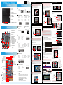
MotherboardIllustration
BackPanel
SZ77R5QuickGuide【English】
FrontPanel
JumperSettings
3=A_RX_P 4=Ground
7=Ground 8=
A_Data_N
11=B_Data_P 12=B_Data_N
15=B_TX_N 16=Ground
19=5VCC 20=NA
1 2 3 4 5 6 7 8 9 10
11 12 13 14 15 16 17 18 19 20
J3
COMHeader(COM1)
1=DCD 2=RXD
3=TXD 4=
DTR
5=Ground 6=DSR
7=RTS 8=CTS
9=Ring 10=NA
97531
108642
J8
LPCHeader(JP1)
1=+12V 2=5V
5=CLK_48M 6=
CLK_33M
9=LAD3 10=LAD2
13=Ring 14=LDRQ0
17=LAD0 18=+3.3V
3=5VSB 4=SERIRQ
7=SIO_RST 8=
LFRAME
11=-12V 12=3VSB
15=SIO_PME 16=LAD1
19=GND 20=NA
1 2 3 4 5 6 7 8 9 10
11 12 13 14 15 16 17 18 19 20
1=5V
2=NA
3=Ground
4=GPIO1
5=GPIO2
J2
CIRHeader(JP6)
1 2 3 4 5
B10
B9
B11
B13
B15
B6
B3
B14
B7
B12
B15
B4
B5
B8
B2
B15
B1
2xUSB2.0&eSATAPorts
COMHeader-COM1
CIRHeader-JP6
Intel
®
64Chipset
USBHeader-USB1
AUX_INConnector
S/PDIFOutPut
Connector-JP2
J6
J7
J10
Please do not apply excess amount of thermal paste.
Thermal Paste
application area
ConnecttheSerialATA
Cabletomotherboard.
1. Install the Mini PCIe card into the Mini PCIe slot / mSATA Slot and affix it
with screws.
D. Mini PCIe card Installation
F7
F1
F5
F2
F6
F8 F9
F11
F10
F3
F4
MiniPCIeSlot
MiniPCIeslotwith
mSATAsupport
62R-SZ77R0-0601 SZ77R5
English.Spanish.Korean.
Traditional Chinese.Japanese.
French. German Quick Guide
53R-SZ77R3-2001
F1. 5.25”Bay
F2. 3.5”Bay
F3. EjectButton
F4. OpenDoor
F5. PowerSwitch&PowerLED
F6. HDDLED
F7. USB3.0Ports
F8. USB2.0Port
F9. MicIn
F10.Headphone
F11.USB2.0Port&FastCharger
SafetyInformation
ReadthefollowingprecautionsbeforesettingupaShuttleXPC.
Laser compliance statement
TheopticaldiscdriveinthisPCisalaserproduct.
Thedrive'sclassicationlabelislocatedonthedrive.
CLASS 1 LASER PRODUCT
EAUTION INVISIBLELASERRADIATIONWHENOPEN.
AVOIDEXPOSURETOBEAM.
CAUTION
Incorrectlyreplacingthebatterymaydamagethiscomputer.
ReplaceonlywiththesameorequivalentasrecommendedbyShuttle.
Disposalofusedbatteriesaccordingtothemanufacturer'sinstructions.
A
B
1
2

 1
1

Xtreme XCA2-1016-BLK User manual
Sharkoon 4044951010950 Datasheet
Avalue Technology LPC-15WD510 Quick Reference Manual
MSI A78M-E45 V2 Quick start guide
Supermicro X9SAE User manual
Supermicro X8SIU-F User manual
Zotac E2-1800-ITX-WiFi Series User manual
Intel 32882 User manual
Commell MS-C75 User manual
Tyan S5535 Quick Reference Manual