KitchenAid KGCD807XBL Installation guide

Category
Cookers
Type
Installation guide
30" (76.2 CM) GAS DOWNDRAFT COOKTOP
INSTALLATION INSTRUCTIONS
INSTRUCTIONS D'INSTALLATION DE LA TABLE DE
CUISSON À GAZ À ASPIRATION
PAR LE BAS DE 30" (76,2 CM)
W10526087A
Table of Contents/Table des matières
COOKTOP SAFETY........................................................................2
INSTALLATION REQUIREMENTS ................................................3
Tools and Parts ............................................................................3
Location Requirements ................................................................3
Venting Requirements..................................................................5
Venting Methods ..........................................................................6
Electrical Requirements ...............................................................8
Gas Supply Requirements ...........................................................8
INSTALLATION INSTRUCTIONS ..................................................9
Install Cooktop .............................................................................9
Rotate Blower - Optional............................................................10
Make Gas Connection................................................................10
Electronic Ignition System..........................................................11
Complete Installation..................................................................12
SÉCURITÉ DE LA TABLE DE CUISSON .................................13
EXIGENCES D'INSTALLATION................................................14
Outils et pièces........................................................................14
Exigences d’emplacement......................................................14
Exigences concernant l’évacuation ........................................16
Méthodes d’évacuation...........................................................17
Spécifications électriques .......................................................19
Spécifications de l'alimentation en gaz ..................................19
INSTRUCTIONS D’INSTALLATION .........................................21
Installation de la table de cuisson...........................................21
Rotation du ventilateur - Facultative.......................................21
Raccordement au gaz.............................................................22
Système d'allumage électronique...........................................23
Achever l'installation ...............................................................24
IMPORTANT:
Installer: Leave installation instructions with the homeowner.
Homeowner: Keep installation instructions for future reference.
IMPORTANT :
Installateur : Remettre les instructions d'installation au propriétaire.
Propriétaire : Conserver les instructions d'installation pour référence ultérieure.
2
COOKTOP SAFETY
You can be killed or seriously injured if you don't immediately
You
can be killed or seriously injured if you don't
follow
All safety messages will tell you what the potential hazard is, tell you how to reduce the chance of injury, and tell you what can
happen if the instructions are not followed.
Your safety and the safety of others are very important.
We have provided many important safety messages in this manual and on your appliance. Always read and obey all safety
messages.
This is the safety alert symbol.
This symbol alerts you to potential hazards that can kill or hurt you and others.
All safety messages will follow the safety alert symbol and either the word “DANGER” or “WARNING.”
These words mean:
follow instructions.
instructions.
DANGER
WARNING
WARNING: If the information in this manual is not followed exactly, a fire or explosion
may result causing property damage, personal injury or death.
Do not store or use gasoline or other flammable vapors and liquids in the vicinity of this
or any other appliance.
WHAT TO DO IF YOU SMELL GAS:
Do not try to light any appliance.
Do not touch any electrical switch.
Do not use any phone in your building.
Immediately call your gas supplier from a neighbor's phone. Follow the gas supplier's
instructions.
If you cannot reach your gas supplier, call the fire department.
Installation and service must be performed by a qualified installer, service agency or
the gas supplier.
WARNING: Gas leaks cannot always be detected by smell.
Gas suppliers recommend that you use a gas detector approved by UL or CSA.
For more information, contact your gas supplier.
If a gas leak is detected, follow the “What to do if you smell gas” instructions.
IMPORTANT: Do not install a ventilation system that blows air downward toward this gas cooking appliance. This type of
ventilation system may cause ignition and combustion problems with this gas cooking appliance resulting in personal injury or
unintended operation.
3
INSTALLATION REQUIREMENTS
Tools and Parts
Gather the required tools and parts before starting installation.
Read and follow the instructions provided with any tools listed
here.
Tools needed
Parts supplied
Parts needed
Metal ducting
Vent clamps
Wall cap
6" (15.2 cm) Round Surface Wall Cap Damper
Order Part Number A406
5" (12.7 cm) Round Surface Wall Cap Damper
Order Part Number A405
3¼" x 10" (8.3 x 25.4 cm) Surface Wall Cap Damper
Order Part Number A403
To order, see the “Assistance or Service” section of the Use
and Care Guide.
Check local codes and consult gas supplier. Check existing gas
supply and electrical supply. See “Electrical Requirements” and
“Gas Supply Requirements” sections.
It is recommended that all electrical connections be made by a
licensed, qualified electrical installer.
Location Requirements
IMPORTANT: Observe all governing codes and ordinances.
When installing cooktop, use minimum dimensions given.
It is the installer’s responsibility to comply with installation
clearances specified on the model/serial rating plate. The
model/serial rating plate is located on side of the downdraft
plenum.
To eliminate the risk of burns or fire by reaching over the
heated surface units, cabinet storage space located above
the surface units should be avoided. If cabinet storage is to
be provided, the risk can be reduced by installing a range
hood that projects horizontally a minimum of 5" (12.7 cm)
beyond the bottom of the cabinets.
The cooktop should be installed in a location away from
strong draft areas, such as windows, doors and strong
heating vents or fans.
All openings in the wall or floor where cooktop is to be
installed must be sealed.
Cabinet opening dimensions that are shown must be used.
Given dimensions are minimum clearances.
Grounded electrical supply is required. See “Electrical
Requirements” section. Proper gas supply connection must
be available. See “Gas Supply Requirements” section.
The cooktop is designed to hang from the countertop by its
side or rear flanges.
The gas and electric supply should be located as shown in
“Cabinet Dimensions” section so that they are accessible
without requiring removal of the cooktop.
Provide cutout in right rear corner of cutout enclosure as
shown to provide clearance for gas inlet, power supply cord,
and to allow the rating label to be visible.
If cabinet has drawers, drawers will need to be removed and
drawer fronts installed on front of cabinet.
IMPORTANT: An undercounter built-in oven cannot be installed
under this product.
IMPORTANT: To avoid damage to your cabinets, check with your
builder or cabinet supplier to make sure that the materials used
will not discolor, delaminate or sustain other damage.
Mobile Home - Additional Installation Requirements
The installation of this cooktop must conform to the
Manufactured Home Construction and Safety Standard, Title 24
CFR, Part 3280 (formerly the Federal Standard for Mobile Home
Construction and Safety, Title 24, HUD Part 280). When such
standard is not applicable, use the Standard for Manufactured
Home Installations, ANSI A225.1/NFPA 501A or local codes.
In Canada, the installation of this cooktop must conform with
the current standards CAN/CSA-A240-latest edition, or with
local codes.
In the State of Massachusetts, the following installation instructions apply:
Installations and repairs must be performed by a qualified or licensed contractor, plumber, or gasfitter qualified or licensed by
the State of Massachusetts.
If using a ball valve, it shall be a T-handle type.
A flexible gas connector, when used, must not exceed 3 feet.
Tape measure
Flat-blade screwdriver
Phillips head screwdriver
Drill
Level
Marker or pencil
Pliers
¼" drill bit
Jigsaw
Ratchet with ³⁄₈" socket
Pipe-joint compound
resistant to LP gas
Noncorrosive leak-detection
solution
Vent grill
Pre-filter
LP conversion kit
Burner caps
Burner grates
Pressure regulator
4
Product Dimensions
30" (76.2 cm) Cooktop
Cabinet Dimensions
NOTES: After making the countertop cutout, some installations
may require notching down the base cabinet side walls to clear
the cooktop base. To avoid this modification, use a base cabinet
with sidewalls wider than the cutout.
A minimum side clearance of 6" (15.2 cm) is recommended
between side of cooktop and side wall for maximum
ventilation performance.
A minimum clearance of 2" (5.1 cm) is recommended
between the motor/blower and cabinet for proper cooling. A
6" (15.2 cm) clearance is recommended for servicing access.
A. 21
³⁷⁄₆₄
" (54.8 cm) with stainless steel trim or
21½" (54.6 cm) without stainless steel trim
B. 19
⁴⁷⁄₆₄
" (50.1 cm) screw head to screw head
C. Model/serial rating/clearance plate location
A. 29
¹⁵⁄₁₆
" (76.1 cm) without
stainless steel trim
B. 30
¹⁄₃₂
" (76.3 cm) with
stainless steel trim
C. 12
²⁹⁄₆₄
" (31.6 cm) centerline of
cooktop to centerline of gas
manifold pipe
D. 7
⁵⁄₁₆
" (18.6 cm)
E. 3
³⁹⁄₆₄
" (9.2 cm)
F. 15" (38.1 cm)
G. 2
⁵⁄₃₂
" (5.5 cm) recommended
minimum cabinet to motor
clearance
H. 14
¹¹⁄₃₂
" (36.4 cm)
I. 11
⁴⁹⁄₆₄
" (29.9 cm)
J.
28³⁄₈
" (72.1 cm) screw head to
screw head
A
B
C
A
B
C
D
E
F
G
H
I
J
A. 30" (76.2 cm)
B. Combustible area above countertop (shown by dashed box above)
C. 30" (76.2 cm) minimum clearance between top of cooktop platform
and bottom of uncovered wood or metal cabinet (24" [61.0 cm]
minimum clearance if bottom of wood or metal cabinet is covered
by not less than ¼" [0.6 cm] flame retardant millboard covered with
not less than No. 28 MSG sheet steel, 0.015" [0.04 cm] stainless
steel, or 0.024" [0.06 cm] aluminum or 0.020" [0.05 cm] copper)
D. 13" (33.0 cm) recommended upper cabinet depth
E. 2
¹⁄₈
" (5.4 cm)
F. 1 9
¹⁵⁄₁₆
" (50.6 cm)
G. 18" (45.7 cm) minimum clearance from upper cabinet to countertop
within minimum horizontal clearances to cooktop
H. Junction box or outlet; 12" (30.5 cm) minimum from bottom of
countertop
I. Junction box or outlet; 10" (25.4 cm) from right-hand side of
cabinet
J. 28
⁵⁄₈
" (72.7cm) on 30" (76.2 cm) models
K. 8" (20.3 cm) minimum distance to nearest left and right side
combustible surface above cooktop
L. 2" (5.1 cm) minimum clearance between back wall and countertop
M. Gas line opening - Wall: anywhere 6" (15.2 cm) below underside of
countertop on the left side. Cabinet floor: anywhere within
6" (15.2 cm) of rear wall on the left side is recommended.
N. 25" (63.5 cm) depth of countertop
B
D
A
E
F
H
I
K
L
K
M
C
G
N
J
M
5
Cutout Dimensions
Venting Requirements
IMPORTANT: This cooktop must be exhausted outdoors.
Do not terminate the vent system in an attic or other enclosed
area.
Use a vent cap.
Vent system must terminate to the outside.
Use only a 6" (15.2 cm) diameter round or 3 ¼" x 10"
(8.3 x 25.4 cm) rectangular vent except as follows: For gas
models, a 5" (12.7 cm) diameter round vent must be used if
the duct length is 10 ft (3.0 m) or less.
Before making cutouts, make sure there is proper clearance
within the wall or floor for the exhaust vent.
Do not cut a joist or stud unless absolutely necessary. If a
joist or stud must be cut, then a supporting frame must be
constructed.
The size of the vent should be uniform.
The vent system must have a damper. If roof or wall cap has a
damper, do not use damper supplied with the range hood.
Use vent clamps to seal all joints in the vent system.
Use caulking to seal exterior wall or roof opening around the
cap.
Determine which venting method is best for your application.
For Best Performance:
Use 26-gauge minimum galvanized or 25-gauge minimum
aluminum metal vent. Poor quality pipe fittings can reduce
airflow. Flexible metal vent is not recommended.
NOTE: Local codes may require a heavier gauge material.
Metal duct may be reduced to 30-gauge galvanized steel or
26-gauge aluminized steel if allowed by local codes. This
reduction is based on information in the International
Residential Codes Section M1601.1 (2006 edition).
Do not install 2 elbows together.
Use no more than three 90° elbows.
If an elbow is used, install it as far away as possible from the
hood’s vent motor exhaust opening.
Make sure there is a minimum of 18" (45.7 cm) of straight
vent between the elbows if more than one elbow is used.
Elbows too close together can cause excess turbulence that
reduces airflow.
Do not use a 5" (12.7 cm) elbow in a 6" (15.2 cm) or 3¹⁄₄" x 10"
(8.3 x 25.4 cm) system.
Do not reduce to a 5" (12.7 cm) system after using
6" (15.2 cm) or 3¹⁄₄" x 10" (8.3 x 25.4 cm) fittings.
Avoid forming handmade crimps. Handmade crimps may
restrict airflow.
Use the wall caps listed in the “Tools and Parts” section for
best performance. If an alternate wall or roof cap is used, be
certain the cap size is not reduced and that it has a back draft
damper.
Use vent clamps to seal all joints in the vent system.
Use caulking to seal exterior wall or roof opening around the
cap.
The length of vent system and number of elbows should be kept
to a minimum to provide efficient performance.
The maximum equivalent length of the vent system is 60 ft
(18.3 m). For altitudes above 4,500 ft (1272 m), reduce
recommended vent run by 20% for best performance.
Cold Weather Installations
An additional back draft damper should be installed to minimize
backward cold air flow and a thermal break installed to minimize
conduction of outside temperatures as part of the vent system.
The damper should be on the cold air side of the thermal break.
Makeup Air
Local building codes may require the use of makeup air systems
when using ventilation systems greater than specified CFM of air
movement. The specified CFM varies from locale to locale.
Consult your HVAC professional for specific requirements in your
area.
A. 28
⁵⁄₈
" (72.7 cm) maximum
B. 19
¹⁵⁄₁₆
" (50.6 cm) maximum
C. 9
⁵⁄₁₆
" (21.6 cm)
D. 6
⁴⁹⁄₆₄
" (17.2 cm)
E. 2
¹⁄₈
" (5.4 cm) minimum space to front edge of cooktop
F. Floor exhaust option
G. 6
¹⁄₈
" (15.6 cm) for 6" (15.2 cm) vent system and 5
¹⁄₈
" (13.1 cm) for
5" (12.7 cm) vent system
H. 9
⁵⁄₁₆
" (21.6 cm)
I. 13
³⁄₈
" (33.9 cm) from the top of the countertop surface
J. Wall exhaust option
A
B
C
D
E
F
G
H
I
J
6
Venting Methods
Common venting methods are shown for a counter-mounted
downdraft cooktop. The cooktop may be vented through the wall
or floor.
Concrete Slab Installations -
Exhaust Through Window Well
Concrete Slab Installations - Exhaust Through Wall
Option 1 - Roof Venting Option 2 - Wall Venting
A. Roof cap
B. 6" (15.2 cm) round roof
venting
A. 6" (15.2 cm) round wall
venting
B. Wall cap
Option 3 - Venting Between
Floor Joist
Option 4 - Venting behind
Cabinet Kick Plate
A. Wall cap
B. 6" (15.2 cm) round wall
venting
A. Wall cap
B. 6" (15.2 cm) round wall
venting
A
B
A
B
A. Wall cap
B. 12" (30.5 cm) minimum
C. Concrete slab
D. 6" (15.2 cm) round PVC sewer pipe
E. 5" to 6" (12.7 cm to 15.2 cm) transition
F. 6" (15.2 cm) round metal duct
G. 6" (15.2 cm) round PVC coupling
H. 6" (15.2 cm) round PVC sewer pipe
I. 6" (15.2 cm) round 90° PVC sewer pipe elbow
J. Tightly pack gravel or sand completely around pipe.
K. 42 ft (12.8 m) max.
L. 6" (15.2 cm) round PVC coupling
M. 6" (15.2 cm) minimum
N. Window well
A. Wall cap
B. 6" (15.2 cm) round metal vent
C. 16" (40.6 cm) maximum
D. 6" (15.2 cm) round PVC sewer pipe
E. 5" to 6" (12.7 cm to 15.2 cm) transition
F. 6" (15.2 cm) round metal duct
G. 6" (15.2 cm) round PVC coupling
H. Concrete slab
I. 6" (15.2 cm) round PVC sewer pipe
J. 6" (15.2 cm) round 90° PVC sewer pipe elbow
K. Tightly pack gravel or sand completely around pipe.
L. 30 ft (9.1 m) max.
M. 6" (15.2 cm) round 90° PVC sewer pipe elbow
N. 6" (15.2 cm) round PVC coupling
O. 12" (30.5 cm) minimum
A
B
C
D
E
F
G
H
I
J
L
M
K
N
A
B
C
D
E
F
G
H
I
J
M
K
N
O
L
7
Calculating Vent System Length
To calculate the length of the system you need, add the
equivalent feet (meters) for each vent piece used in the system.
Example vent system
NOTE: Flexible vent is not recommended. Flexible vent creates
back pressure and air turbulence that greatly reduce
performance.
Determine Range Blower Setting
This cooktop is equipped with a dual range blower. It is shipped
from the factory in the low range for most installations. If the
equivalent duct length exceeds 30 ft (9.1 m), it must be converted
to high range. Do not convert the blower to high range for shorter
lengths; this will cause excessive noise and conditioned air loss.
Convert blower before installing into countertop if necessary.
To Convert to High Range:
1. Place cooktop on floor with front edge and plenum down.
2. Remove the four #10 - 32 locknuts (A) that attach the blower
motor assembly to the blower exhaust scroll.
3. Remove the blower motor assembly (B) from the blower
exhaust scroll (E).
4. Slowly reach into the blower exhaust scroll opening and
remove the retainer (C).
5. Gently remove the restrictor ring (D).
6. Place the motor assembly back on the studs of the blower
exhaust scroll.
7. Reattach the four #10-32 locknuts to secure the blower motor
assembly back to the blower exhaust scroll.
Vent Piece 6" (15.2 cm) Round
45° elbow 2.5 ft
(0.8 m)
90° elbow 5.0 ft
(1.5 m)
6" (15.2 cm)
wall cap
0.0 ft
(0.0 m)
3¹⁄₄" x 10" (8.3 cm x 25.4 cm)
to 6" (15.2 cm) transition
4.5 ft
(1.4 m)
6" (15.2 cm) to 3¹⁄₄" x 10"
(8.3 cm x 25.4 cm) transition
1 ft
(0.3 m)
3¹⁄₄" x 10" (8.3 cm x 25.4 cm)
to 6" (15.2 cm) 90° elbow
transition
9.0 ft
(2.7 m)
6" (15.2 cm) to 3¹⁄₄" x 10"
(8.3 cm x 25.4 cm) 90° elbow
transition
5.0 ft
(1.5 m)
3¹⁄₄" x 10" (8.3 cm x 25.4 cm)
90° elbow
5.0 ft
(1.5 m)
3¹⁄₄" x 10" (8.3 cm x 25.4 cm)
flat elbow
12.0 ft
(3.7 m)
3¹⁄₄" x 10" (8.3 cm x 25.4 cm)
wall cap
0.0 ft
(0.0 m)
5" to 6" (12.7 cm to 15.2 cm)
transition
1 ft
(0.3 m)
1- 90° elbow = 5 ft (1.5 m)
8 ft (2.4 m) straight = 8 ft (2.4 m)
1 - wall cap = 0 ft (0 m)
System length = 13 ft (3.9 m)
A. #10 - 32 locknut
B. Blower motor and wheel assembly
C. Retainer
D. Restrictor ring
E. Exhaust scroll
F. Blower wheel guard
90˚ elbow
2 ft
(0.6 m)
6 ft (1.8 m)
wall cap
A
B
C
D
EF
8
Electrical Requirements
IMPORTANT: The cooktop must be electrically grounded in
accordance with local codes and ordinances, or in the absence
of local codes, with the National Electrical Code, ANSI/NFPA 70
or Canadian Electrical Code, CSA C22.1.
This cooktop is equipped with an electronic ignition system that
will not operate if plugged into an outlet that is not properly
polarized.
If codes permit and a separate ground wire is used, it is
recommended that a qualified electrical installer determine that
the ground path is adequate.
A copy of the above code standards can be obtained from:
National Fire Protection Association
1 Batterymarch Park
Quincy, MA 02169-7471
CSA International
8501 East Pleasant Valley Road
Cleveland, Ohio 44131-5575
A 120 volt, 60 Hz, AC only, 15-amp, fused electrical circuit is
required. A time-delay fuse or circuit breaker is also
recommended. It is recommended that a separate circuit
serving only this cooktop be provided.
Electronic ignition systems operate within wide voltage limits,
but proper grounding and polarity are necessary. Check that
the outlet provides 120-volt power and is correctly grounded.
The wiring diagrams are provided with this cooktop. See
“Wiring Diagrams” on a separate sheet. The wiring diagrams
are located on the left underside of the cooktop base.
Gas Supply Requirements
Observe all governing codes and ordinances.
IMPORTANT: This installation must conform with all local codes
and ordinances. In the absence of local codes, installation must
conform with American National Standard, National Fuel Gas
Code ANSI Z223.1 - latest edition or CAN/CGA B149 - latest
edition.
IMPORTANT: Leak testing of the cooktop must be conducted
according to the manufacturer’s instructions.
Type of Gas
Natural Gas:
This cooktop is design-certified by CSA International for use with
Natural gas or, after proper conversion, for use with LP gas.
This cooktop is factory set for use with Natural gas. If
converting to LP gas, see the “LP Gas Conversion”
instructions provided in the package containing literature.
The model/serial rating plate located on the underside of the
cooktop base has information on the types of gas that can be
used. If the types of gas listed do not include the type of gas
available, check with the local gas supplier.
LP Gas Conversion:
Conversion must be done by a qualified service technician.
No attempt shall be made to convert the cooktop from the gas
specified on the model/serial rating plate for use with a different
gas without consulting the serving gas supplier. See the Gas
Conversion instructions provided in the package containing
literature.
Gas Supply Line
Provide a gas supply line of ³⁄₄" (1.9 cm) rigid pipe to the
cooktop location. A smaller size pipe on longer runs may
result in insufficient gas supply. Pipe-joint compounds that
resist the action of LP gas must be used. Do not use
TEFLON
®†
tape. With LP gas, piping or tubing size should be
½" minimum. Usually, LP gas suppliers determine the size
and materials used in the system.
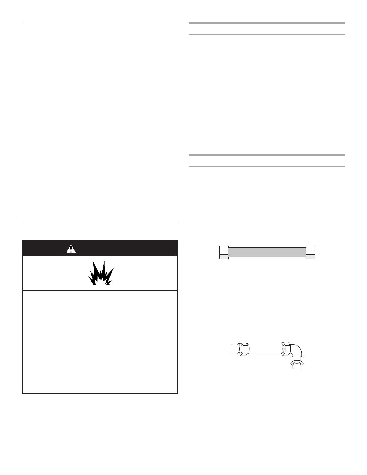
Flexible metal appliance connector:
If local codes permit, use a ¹⁄₂" or ³⁄₄" I.D. flexible stainless
steel tubing gas connector, designed by CSA to connect
the cooktop to the rigid gas supply line.
A ½" male pipe thread is needed for connection to the
female pipe threads of the inlet to the cooktop pressure
regulator.
Do not kink or damage the flexible metal tubing when
moving the cooktop.
Rigid pipe connection:
The rigid pipe connection requires a combination of pipe
fittings to obtain an in-line connection to the cooktop. The
rigid pipe must be level with the cooktop connection. All
strains must be removed from the supply and fuel lines so
cooktop will be level and in line.
WARNING
Explosion Hazard
Use a new CSA International approved gas supply line.
Install a shut-off valve.
Securely tighten all gas connections.
If connected to LP, have a qualified person make sure
gas pressure does not exceed 14" (36 cm) water
column.
Examples of a qualified person include:
licensed heating personnel,
authorized gas company personnel, and
authorized service personnel.
Failure to do so can result in death, explosion, or fire.
†®TEFLON is a registered trademark of E.I. Du Pont De Nemours and Company.
9
Must include a shutoff valve:
The supply line must be equipped with a manual shutoff
valve. This valve should be located in the same room but
external to the cooktop opening, such as an adjacent
cabinet. It must be accessible without removing the cooktop,
and it should be in a location that allows ease of opening and
closing. Do not block access to shutoff valve. The valve is for
turning on or shutting off gas to the cooktop.
Gas Pressure Regulator
The gas pressure regulator supplied with this cooktop must be
used. The inlet pressure to the regulator should be as follows for
proper operation:
Natural Gas:
Minimum pressure: 5" (12.7 cm) WCP
Maximum pressure: 7" to 14" (17.8 cm to 35.5 cm) WCP
LP Gas:
Minimum pressure: 10" (25.4 cm) WCP
Maximum pressure: 14" (35.5 cm) WCP
Contact local gas supplier if you are not sure about the inlet
pressure.
Burner Input Requirements
Input ratings shown on the model/serial rating plate are for
elevations up to 2,000 ft (609.6 m).
For elevations above 2,000 ft (609.6 m), ratings should be
reduced at a rate of 4% for each 1,000 ft (304.8 m) above sea
level (not applicable for Canada).
Gas Supply Pressure Testing
Gas supply pressure for testing regulator must be at least
1" water column pressure above the manifold pressure shown on
the model/serial rating plate.
Line pressure testing above ½ psi gauge (14" WCP)
The cooktop and its individual shutoff valve must be
disconnected from the gas supply piping system during any
pressure testing of that system at test pressures in excess of
½ psi (3.5 kPa).
Line pressure testing at ½ psi gauge (14" WCP) or lower
The cooktop must be isolated from the gas supply piping system
by closing its individual manual shutoff valve during any pressure
testing of the gas supply piping system at test pressures equal to
or less than ½ psi (3.5 kPa).
INSTALLATION INSTRUCTIONS
Install Cooktop
Decide on the final location for the cooktop.
1. Open carton as instructed on product packaging.
2. Remove shipping materials and tape from cooktop.
3. Remove the removable grease filter by lifting the filter out.
4. For island or peninsula installations, go to the “Rotate Blower
- Optional” section.
5. Using 2 or more people, remove the cooktop from the carton.
REMEMBER: An undercounter built-in oven cannot be
installed under this cooktop.
A. Gas supply line
B. Shutoff valve “open” position
C. To cooktop
A
B
C
WARNING
Excessive Weight Hazard
Use two or more people to move and install cooktop.
Failure to do so can result in back or other injury.
A. Removable grease filter
B. Left side grate
C. Vent grille
D. Right side grate
A
B
C
D
10
6. Place cooktop right side up into the cutout.
NOTE: Make sure that the front edge of the cooktop is
parallel to the front edge of the countertop. If repositioning is
needed, lift entire cooktop up from the cutout to avoid
scratching the countertop.
7. Connect blower exhaust scroll to ducting.
8. Use vent clamps to secure the ducting to the blower exhaust
scroll.
9. Reinstall grease filter.
10. Reinstall vent grille.
Rotate Blower - Optional
IMPORTANT: The following additional steps must be performed
if the product is being installed in peninsula or island cabinetry.
The blower exhaust scroll is shipped from the factory set to
exhaust straight out the back of the cabinet through an exterior
wall.
To rotate blower:
1. Remove the right and left grates. Then remove the vent grille.
See illustration in Step 4 of the “Install Cooktop” section.
2. Locate the 4 locknuts inside the plenum.
3. Use ³⁄₈" socket and ratchet handle to loosen the nut half of a
rotation. Repeat this process for each of the 4 nuts.
4. With the nuts loosened, the blower exhaust scroll can be
easily rotated downward.
5. Retighten each nut with the ³⁄₈" socket, extension and ratchet.
Make Gas Connection
1. Apply pipe-joint compound made for use with Natural and LP
gas to the smaller thread ends of the flexible connector
adapters (see C and G in the following illustration).
2. Attach one adapter to the gas pressure regulator and the
other adapter to the gas shutoff valve. Tighten both adapters.
3. Use a ¹⁵⁄₁₆" combination wrench and channel lock pliers to
attach the flexible connector to the adapters. Check that
connector is not kinked.
A. Blower exhaust scroll
B. Plenum
C. Blower motor
D. #10-32 locknuts (4)
E. Motor mounting plate
A. #10 - 32 locknut
B. Plenum
C. Flat washer
D. Blower guard
D
C
A
D
E
B
A
C
D
B
WARNING
Explosion Hazard
Use a new CSA International approved gas supply line.
Install a shut-off valve.
Securely tighten all gas connections.
If connected to LP, have a qualified person make sure
gas pressure does not exceed 14" (36 cm) water
column.
Examples of a qualified person include:
licensed heating personnel,
authorized gas company personnel, and
authorized service personnel.
Failure to do so can result in death, explosion, or fire.
11
Typical flexible connection.
4. Install the pressure regulator with the arrow pointing up
toward the bottom of the cooktop base and in a position
where you can reach the regulator access cap.
IMPORTANT: All connections must be wrench-tightened. Do
not make connections to the gas regulator too tight. Making
the connections too tight may crack the regulator and cause
a gas leak. Do not allow the regulator to turn on the pipe
when tightening fittings.
Use only pipe-joint compound made for use with Natural and LP
gas.
Do not use TEFLON
®
tape. You will need to determine the fittings
required depending on your installation.
Complete Connection
1. Open the manual shutoff valve in the gas supply line. The
valve is open when the handle is parallel to the gas pipe.
2. Test all connections by brushing on an approved
noncorrosive leak-detection solution. If bubbles appear, a
leak is indicated. Correct any leak found.
3. Remove surface burner caps and grates from parts package.
Align notches in burner caps with pins in burner base. Burner
caps should be level when properly positioned. If burner caps
are not properly positioned, surface burners will not light.
Place burner grates over burners and caps.
4. Plug into a grounded 3 prong outlet.
Electronic Ignition System
Initial lighting and gas flame adjustments
This cooktop is equipped for electronic auto-reignition by means
of a spark igniter located at the rear of each burner. The burners
are designed to light at any valve rotation that admits sufficient
gas flow to support a flame and to automatically relight following
a loss of flame due to a draft or other adverse condition. This
feature is provided only as a convenience.
Check Operation of Surface Burners
Push in and turn the surface burners control knobs to light.
The surface burner flame should light within 4 seconds. The first
time a surface burner is lit, it may take longer that 4 seconds to
light because of air in the gas line.
Check the flame on “HIGH” for a blue color. It should be clean
and soft in character. No yellow tip, blowing or lifting of flame
should occur. Occasional orange flashes are normal and reflect
different elements in the air or gas.
A. Manifold entrance
B. Gas pressure regulator
C. Use pipe-joint compound.
D. Adapter (must have ½" male pipe thread)
E. Flexible connector
F. A d ap t e r
G. Use pipe-joint compound.
H. Manual gas shutoff valve
I. ½" or ¾" gas pipe
A. Access cap
B. Rear of cooktop
C. Gas pressure regulator
D. Up arrow. Regulator must be installed with
arrow pointing up to cooktop bottom.
A. Closed valve
B. Open valve
A
B
D
E
C
F
G
H
I
A
B
C
D
A
B
A. Burner cap
B. Burner ports
C. Burner base
D. Gas tube opening
E. Igniter head
A
B
C
D
E
Electrical Shock Hazard
Plug into a grounded 3 prong outlet.
Do not remove ground prong.
Do not use an adapter.
Do not use an extension cord.
Failure to follow these instructions can result in death,
fire, or electrical shock.
WARNING
12
After verifying the proper burner operation, turn the control knobs
to “OFF.”
If burners do not light properly:
Turn surface burner control knob to the “OFF” position.
Check that the power supply cord is plugged in and the
circuit breaker has not tripped or the fuse blown.
Check that the gas shutoff valves are set to the “open”
position.
Check that burner caps are properly positioned on burner
bases.
Recheck operation of surface burners. If a burner does not light
at this point, contact your dealer or authorized service company
for assistance.
Adjust Flame Height
Smart Port Burner System
This cooktop is equipped with a Smart Port Burner System. The
Smart Port Burner System produces a small flame directly under
each grate finger and a larger flame between each grate finger.
The visual difference between the ports will be noticeable when
the burner is used or when adjustments are made to the flame
length.
Adjust the height of top burner flames. The cooktop “low” burner
flame should be a steady blue flame approximately ¼" (0.64 cm)
high.
To adjust standard burners:
The flame can be adjusted using the adjustment screw in the
center of the valve stem. The valve stem is located directly
underneath the control knob.
If the “low” flame needs to be adjusted:
1. Light 1 burner and turn to lowest setting.
2. Remove the control knob.
3. Hold the knob stem in the low position using a pair of pliers.
Use an ¹⁄₈" (3.0 mm) flat-blade screwdriver to turn the screw
located in the center of the control knob stem until the flame
is the proper size.
4. Replace the control knob.
5. Test the flame by turning the control from “LO” to “HI,”
checking the flame at each setting.
6. Repeat the above steps for each burner.
Complete Installation
1. Check that all parts are now installed. If there is an extra part,
go back through the steps to see which step was skipped.
2. Check that you have all your tools.
3. Dispose of/recycle all packaging materials.
4. Use a mild solution of liquid household cleaner and warm
water to clean cooktop before use. Dry thoroughly with a soft
cloth. For more information, see the “Cooktop Care” section
of the Use and Care Guide.
5. Read “Cooktop Use” in the cooktop Use and Care Guide.
6. Reconnect power.
NOTE: If the cooktop does not work after turning on the power,
check that a circuit breaker has not tripped or a household fuse
has not blown. See “Troubleshooting” section in the Use and
Care Guide for further information.
7. Use the Flow Tester Card provided with your cooktop to
check the airflow (see card for step-by-step instructions).
If you need Assistance or Service:
Please reference the “Assistance or Service” section of the Use
and Care Guide or contact the dealer from whom you purchased
your cooktop.
A. Low flame
B. High flame
A
B
1 / 1

KitchenAid KGCD807XBL Installation guide

Category
Cookers
Type
Installation guide

Ask a question and I''ll find the answer in the document

Finding information in a document is now easier with AI

Ask the document

in other languages