KitchenAid KECD865HBT3 Installation guide

Type
Installation guide
[] []
ui
C
KJtchen_kJd _
FORTHE WAY IT'S MADE _'
Questions regarding features,
operation, performance, parts or
service? Call 1-800o422-1230 or visit
our web site at www.kitchenaid.com
Readandsave these
IMPORTANT:
Installer: Leave installation
Instructions with the homeowner.
Homeowner: Keep Installation
Instructions for future reference.
Save Installation Instructions for local
ebctrical inspector's use.
Write down the model and serial numbers
before installing cooktop.
Both numbers are on the modeVserial
rating plate, located on the bottom of the
cooktop.
Model #
Serial #
Part No. 8285364
Before youstart,,,
Your safety and the safety of
others is very important.
We have provided many important
safety messages in this manual and
on your appliance. Ah_iays read and
obey all safety messages.
This is the safety alert
symbol.This symbol alerts
you to hazards that can kill
or hurt you and others. All safety
messages will be preceded by the
safety alert symbol and the word
"DANGER" or "WARNING". These
words mean:
You witi be killed or seriously
injured if you don't foltow
instructions.
You can be killed or seriously
injured if you don't foltow
instructions.
All safety messages will identify the
hazard, tell you how to reduce the
chance of injury, and tell you what
can happen if the instructionsare
not followed.
Important: Observe all governing
codes and ordinances. Failure to meet
codes and ordinances could lead to
fire or electrical shock.
To eliminate the risk of burns by
reaching over heated surface units,
cabinet storage space located above
the surface units should be avoided, tf
cabinet storage is to be provided, the
risk can be reduced by instalJing a
range hood that projects horizontaJiy a
minimum of 5 inches (12.7 am) beyond
the bottom of the cabinets.
Proper installation is your responsibility.
oMake sure you have everything
necessary for correct installation.
oHave a qualified technician install
this cooktop.
Comply with the electrical specifications
on the model/serial rating plate.
Model/serial rating plate is located on
the bottom of the cooktop. Write both
numbers down on the front cover now
before installing cooktop.
Downdraft cooktop location should be
away from strong draft areas, such as
windows, doors and strong heating vents
or fans. Locate cooktop for convenient
use in kitchen.
Grounded electrical system is required=
See "Electrical requirements," Page 6=
Venting system must terminate
outdoors.
AH openings in the wall or floor where
cooktop is to be installed must be
sealed.
tt is the customer's responsibility to
contact a qualified electrical installer,
to make sure that the electrical
installation is correct, and to make
sure the electrical installation follows
the National EJectrical Code,
ANSJ/NFPA 70 -- latest edition*, or
CSA Standards C22.1=94, Canadian
EJectrical Code, Part 1 and C22.2 No.
0-M91 =latest edition**, and aH local
codes and ordinances.
WARNING: To reduce the risk of fire,
electric shock, or injury to persons,
observe the following:
installation work and electrical wiring
must be done by qualified person(s) in
accordance with all applicable codes
and standards, including fire-rated
construction.
Sufficient air is needed for proper
combustion and exhausting of gases
through the flue (chimney) of fuel
burning equipment to prevent back
drafting. Follow the heating equipment
manufacturer's guideline and safety
standards such as those published by
the American Society for Heating,
Refrigeration and Air Conditioning
Engineers (ASHRAE), and the local
code authorities.
When cutting or drilling into wall or
ceiling, do not damage electrical wiring
and other hidden utilities.
Ducted fans must always be vented to
the outdoors.
WARNING: To reduce the risk of fire,
use only metal ductwork.
This downdraft eooktop is Not approved
for use in mobile homes.
Copies of the standards listed may be
obtained from:
* National Fire Protection Association
Batterymareh Park
Quincy, Massachusetts 02269
** Canadian Standard Association
178 Rexdale Boulevard
Etobicoke, (Toronto), Ontario Mgw 1R3
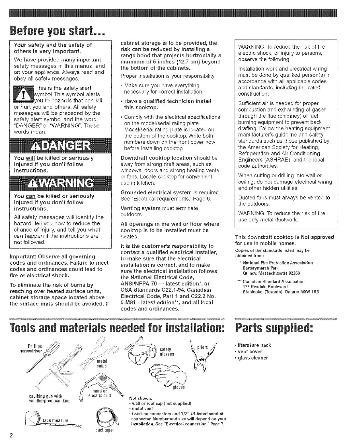
Toolsandmaterials neededfor installation:
PhHHps _, pliers ji
screwdriver // ._ :_:_ safety \_ ;_'Y.:j glasses
...._ snips , _'_
Partssupplied:
* literature pack
* vent cover
* glass cleaner
Not shown:
. wall or roof cap {not supplied)
. metal vent
. twist=on connectors and 1/2" UL=iisted conduit
connecter, Number and size will depend on your
installation. See "E_eetriea_ connection," Page 7.
Product #[mens[ens
J_qr-_. 31-1/2" (88 cm) - 38" (76.2 cm) ceohtep
37-1/2" (95.3 cm) - 36" (91.4 cm) cooktop
width
J
J
Cateat #imensiens
29-112" (74.9 cm) - 38" (76.2 cm) ceoktop
35-1/2" (98.2 cm) - 36" (91.4 cm) ceoktep
cnteat width
cm)
_pth
Select required duct cotont
(see Page 4 for exhaust duct
cutoutlocation}.
2"(5,1 cm) minh_nm
spacetofrontedgeof
cenetertep
Oouetertapmust he
supported within
3" (7.6 cm) of cutout.
14-5/8" (37.1 cm)
blower housing
depth
3-ft. gl.4 cm long
power snpp y cab e
factory installed.
Clearancegimensiens
38" (76.2 cm) rain - 38" (76.2 cm) caoktop
36" (91.4 cm) rain - 36" (91.4 cm) cooktop
whee higher thee 18" (45.7 cm) _1
B
See Note ** [or
minimum clearances
".. %.,
Nieimum distance "'..\ .... _. ---.21"_ (53.3 cm)
te nearestcombustibleS..\ \\_ uo !.Jptseal ,_,,_n_._ opeeing depth
vertical suflace "...._ _ ceo,'{mpto ceante_mp. "_._ _
extendieglS"(45,7cm) _,,', "" _-- --
ohovecoo,top _. ....--_\ \ _................................
29-1/2" (74.9 cm) - 38" (76.2 cm) cooktop
35-1/2" (98.2 cm) - 36" (91.4 cm) ceoktop
cuton_width
Side cJearance-- 6" (15.2 cm) minimum clearance between side
of cooktop and side wall is recommended for maximum
ventilation performance.
Rear cJearance- 3/4" (19.1 mm) clearance between rear edge of
cooktop and rear wall is recommended.
Motor/b_ower c_earance-- 2" (51 mm) minimum clearance
between motor and cabinet is required for proper cooling.
6" (15.2 cm) clearance is recommended for servicing access,
_ Note: 24" {61 era) rainiraura when bottom of wood or rectal cabinet is
protected by not _essthan 1/4" (&4 rare) florae retardant rag_board covered
with not Jessthan No. 28 MSG sheet steel 0.015" {0.4 ram) stainless steel
0,024" (0,6 rare) alurainura or 0,020" (0,5 rare) copper,
30" (7&2 era) rainiraura cJearanee between the top of the cooking p_atfotra
and bottom of unprotected wood or sheet metal
cauntertap
install rear
wall junction
box in shaded
area. Darker
shaded area is
preferred.
5" (12.7 era)
I
fleer
11" (27.9 cm) 8" (28.3 cm)
Minimum base cabinet dimensions --
30" (76.2 cm) base cabinet width
24" (61 cm) base cabinet depth
25" (63.5 cm) countertop depth
Countertop opening dimensions that are shown must
be used. Given dimensions are minimum clearances and
provide required 0" (0 cm) clearance.
New installations -- Follow minimum dimensions given.
Replacement installation -- Be sure that front edge of
cooktop is at least 1-1/2" (38.1 mm) back from front
edge of countertop.
ff cabinet has drawers, drawers will need to be
removed and drawer fronts installed on front of cabinet.
Cutout preparation:
Decorative laminate --
Chamfer all exposed edges to
prevent chipping laminate,
Cut radius corners and file to
smooth edges and to prevent
cracking.
Ventin9systemreqeirements
Venting system must terminate to the
outside.
Do Not terminate the vent system in an
attic or other enclosed space.
Do Not use 4qnch (10 cm) laundry-type
wall caps.
Use metal vent only. Exception: See
"optional venting under a concrete
slab", in "Venting methods" below.
Rigid metat vent is recommended. Do
not use plastic or metal foil vent.
To reduce risk of fire and to properly
exhaust air, be sure to vent air outside.
Do Not vent exhaust air into spaces
within walls or ceilings or into attics,
crawl spaces or garages.
Before making cutouts, make sure there
is proper clearance within the wall or
floor for the exhaust vent.
Do Not cut a joist or stud unless
absolutely necessary. If a joist or stud
must be cut, then a supporting frame
must be constructed.
Vent materials needed for installation
are not supplied,
Determine which venting method to use.
See "Venting methods," below.
Next, determine the equivalent vent length
using chart on Page 5. The maximum
equivalent vent length is 60 feet (18.3 m).
The blower housing is set to vent
straight out the back from the cooktop. To
vent down, left or right, see "Installation,"
Step 2, Page 6.
This downdraft cooktop is rated at
60 feet (18.3 m) of straight vent or the
equivalent.
if vent length is 10 feet (3 m) or less,
6" (15.2 cm) diameter round vent may
be used.
tf vent length is more than 10 feet
(3 m), use 6" (15.2 cm) diameter round
or 3-1/4" x 10" (8.3 x 25.4 cm)
rectangular vent.
Thermal breaks: In areas of extreme
cold weather, it may be necessary to
provide a short length of nonmetallic duct
as close to the wall as possible to prevent
thermal conduction along the metal vent.
For attitudes above 4,500 ft (1372 m),
reduce recommended vent run by 20%.
For the most efficient and
quietest operation:
[_ Use 26=gauge minimum galvanized or
25=gauge minimum aluminum metal
vent. Poor=quality pipe fittings can
reduce air flow. (Note: Local codes may
require a heavier=gauge material.)
Flexible metal vent is Not
recommended.
[_ Do Not exhaust more than one
downdraft cooktop into a single vent
system.
[_ The length of vent and number of
elbows should be kept to a minimum to
provide efficient performance.
_j The size of the vent should be uniform.
D Use the fewest number of 90° elbows.
[_ Do Not install two elbows together.
[_ Make sure there is a minimum of 18"
(45.7 cm) of straight vent between the
elbows if more than one elbow is used.
(Elbows too close together cause
excess turbulence that reduces airflow.)
[_ Do Not use a 5" (12.7 cm) elbow in a
6" (15.2 cm) or 3-1/4" x 10"
(8.3 x 25.4 cm) system.
[_ Do Not reduce back to 5" (12.7 cm)
system after using 6" (15.2 cm) or
3-1/4" x 10" (8.3 x 25.4 cm) fittings.
[_ Avoid forming handmade crimps.
Handmade crimps may restrict airflow.
[_ Use the recommended vent caps for
proper performance. If an alternate wall
or roof cap is used, be certain cap size
is not reduced and that it has a
backdraft damper.
[_ Use duct tape to seal all joints in the
vent system.
[_ Use caulking to seal exterior wall or roof
opening around the cap.
Venting methods
9=5/8''(24.4 ¢m} =30" (752 ¢m) ¢o0kt0p
13=5/16'' 8 eel} =35" (g1.4 ¢m) ¢00kt0p
g=3/4" (24.8 cm)
h01ein rear er
side ef cabinet
The cooktop may be vented through the wall or floor. Common venting methods and the
types of materials needed are shown.
Make sure there is proper clearance within the wall or floor for exhaust vent before
making cutouts.
\
inside wall to roof directly between
or overhang outside floor joists
peninsula
siti0n
@' 5_ elbow_
3ol/4" x 10"
(8.3 x 25,4 nm)
cabinet toe space
to outside
8"(15.2era)roundmetalvent
8"(15.2era)transition
Determine equivalent Jength of vent. Maximum
equivalent length of vent is 60 ft (18.3 m).
List the number of each piece and Uength of straight vent you will use.
MuffipUythe equivalent Uengthby the number of pieces. Add the totals
to get the totaU equivalent Uength of your system.
5" (15.2 era) max. _ \ 5" (15.2 era)
round 90° PVC Tightly pack gravel or sand round 99°
sewer pipe elbow eornpleteJy around pipe. PVC sewer
pipe elbow
optional vent arrangement under
concrete slab
t2" (30.5 era) 5" (15.2 cm) round transition
well
i l_ 42"
6" i (106.7era)
(15.2 era) max.
rain. 6" (15.2 era) round
PVC coupling
90° PVC sewer
pipe elbow
Tightly pack gravel or sand
completely around pipe.
optional vent arrangement through
window welt under concrete slab
90° eUbows(3) = 15ft. (4.6 m)
12 feet (3.7 m) straight = 12ft. (3.7 m)
WaHcap = 0ft.(0m)
EquivaUentUengthof
6" (15.2cm) round system
= 27ft. (8.3 m)
Note: Flexible metal vent is Not recommended.
If it is used, calculate eachfoot (30 cm) of flexible vent
astwo feet (61 cm) of straight metal vent. Flexible
metal elbows count twice as much as standard elbows.
Vent
Piece
straight vent per lineal foot
3-I/4" x 19" (83 x25.4 cm)
6" (152 cm) round
1ft. (30.5cm)
1ft, (30.5cm)
6" (152 cm) flexible 2 ft.
elbow
6" (152 cm) round 450elbow
6" (152 cm) round 99" elbow
_ ---_, 3-I/4" x 10" (8.3 x 25.4 crn)
_:9 flat elbow
3-1/4" x 19" (8.3 x 25.4 crn)
90° elbow
transition to round
_ _::_=__ 3-1/4" x 10" (8.3 x 25_4cm) to
6"<15.2ore/99"elbo
-(-_¢_ air flow
_ -1/4" x 10" (8.3 x 25.4 crn) to
6" (15.2 ern)
transition to flat
i_;_'1 6" (15.2 cm) to
b-r:=_:'_ I' 3-1/4" x 19" 8.3 x 254 cm)
_'_ air flow
wall cap*
[_;_> 3-1/4" X10" (8.3 X25.4 crn)
_'_j_ 6" (152 cm) round
roof cap*
19,,×19,,/954x254
thermaJ break
-_ 6" (152 cm) round
{6t cm)
2.5 ft.
(76,2 m)
5 ft.
(1,5 m}
12ft.
(3,7 m)
5 ft.
(1,5 m)
9 ft.
(2.7 m)
4.5 ft.
(1,4 m)
5 ft.
(1,5 m}
1ft.
(30,5cm)
9 ft.
(9era)
9 ft.
(9era)
9 ft,
(9era)
2 ft.
(6t era)
No. of
Pieces/
Length
Total
EquivaJent
Length
Total equivalent vent system length
* Length for required wall/roof cap has already been incorporated
into rating for maximum vent system length. A suitable wall/roof
cap must be used.
if codespermitandaseparateground
wireisused,it isrecommendedthata
qualifiedelectrician determine that the
ground path is adequate.
Do Not ground to a gas pipe.
Check with a qualified eJectNcian if you
are not sure cooktop is properly
grounded,
Do Not have a fuse in the neutral or
grounding circuit,
The downdraft cooktop must be
connected to the proper electrical voltage
and frequency as specified on the
model/serial rating plate. The model/serial
rating plate is located on the bottom of the
cooktop.
[_ A four-wire or three-wire, single-phase,
240-volt, 60-Hz, AC-only electrical
supply is required on a separate
30-ampere circuit, fused on both sides
of the line.
[_ A time-delay fuse or circuit breaker is
recommended. The fuse size must not
exceed the circuit rating of the
appliance as specified on the
model/serial rating plate.
[_ CONNECT WITH COPPER WIRE
ONLY.
Connected directly to the fused
disconnect (or circuit breaker box)
through flexible, armored or non-
metallic sheathed, copper cable (with
ground wire).
[_ Flexible armored cable should connect
cooktop directly to the junction box.
[_ Fuse both sides of the line.
[_ Locate the junction box to allow as
much slack as possible between the
junction box and cooktop so that the
downdraft cooktop can be moved if
servicing is ever necessary.
[_ A U.L.-listed 1/2" (12.7 mm) conduit
connector must be provided at the
junction box.
The recommended minimum copper
wire size is No.olO gauge. However,
wire sizes and connections must conform
to the requirements of the National
Electrical Code, ANSI/NFPA 70 -- latest
edition*, or CSA Standards C22.1-94,
Canadian Electrical Code, Part 1 and 22.2
No. 0-M91 - latest edition** and all local
codes and ordinances. Wire sizes and
connections must conform with the rating
of the cooktop.
Copies of the standard listed may be obtained from:
* National Fire Protection Association
Batteryrnarch Park
Quincy, Massachusetts 02209
** Canadian Standard Association
178 Rexdale Boulevard
Etobieoke, Ontario MgW 1R$
The wiring diagram is located on the
bottom of the cooktop.
Twist-on connectors and U.L.-Iisted 1/2"
(12.7 mm) conduit connector are not
provided.
m Remove shipping materials andtape
from cooktop.
2m The blower is set to vent straight out
the back of the cooktop.
To vent to the [eft side, right side or down
through the bottom of the cabinet, add an
elbow to the blower assembly exhaust vent.
it may be easier to connect appliance
cable to junction box before inserting
cooktop into cutout. See "Electrical
connections," Page 7.
Excessive Weight Hazard
Use two or more people to move
and install cooktop.
Failure to do so could result in
back or other injury.
Lift entire cooktop up from cutout
when positioning cooktop in
countertop opening.
S_ Insertdowndraflcooktopintocutout.
Checkthat:
[_ cooktopis centeredin cutout.
[_ front edge of downdraflcooktopis at least
1-1/2"(38.1mm)from front edgeof
countertopand parallelto countertop.
[_ rearedge of cooktopis at least3/4"
(!9.! mm)from rearwall as recommended.
[_ sideedgeof cooktopis atleast 6 inches
(!5.2 cm) from sidewall.
Connect vent system. See "Venting
requirements," Pages 4-5. Use duct tape to
seal all ioints. Vent must end with a wall or roof
cap outside the building.
Electrical Shock Hazard
Turn power supply off before
connecting wires.
Use lO=gauge solid copper wire.
Electrically ground cooktop.
Failure to follow these
instructions can result in death,
fire, or electrical shock.
Thiseooktopmust be connected to a
grounded, metallic permanent wiring
system or a ground connector should be
connectedto the ground terminal or wire
lead on the ¢ooktop.
This cooktopis manufacturedwith a frame
connected,green or bare groundwire.Connect
thecooktopcabletothejunction boxthrough
the 1/2"(12.7ram)UA.4isted conduit
connector.Completeelectricalconnection
accordingto localcodes and ordinances,
mMakethe electricalconnection:
1.Disconnect the power supply.
2.Removethejunction boxcoverfromjunction
boxinsidecabinet.
3.Connectcooktoppowersupplycableto
junction boxusinga U.L.-listedconduit
connector.Tightenscrewson conduit
connector.
4.Connectthe two blackwires togetherwith
twist-onconnectors.
5.Connectthe two red wirestogetherwith
twist-onconnectors.
6.Completethe electricalconnection
accordingto localcodes and ordinances.
(See"WiFeconnectionschart.")
Wire connections chart
jormfiae
box
red
wires
cable from fused dissennect
or dr0oit breaker box
white
/ wire
grace or_
bare
g_eued
wure
green ground
appHaoce cable
wure
Figure 1
black
wires
conduif
connector
power supply
sable frora saektop
if local codes DO NOT PERMIT
connecting cooktop-ground
conductor to neutral white wire
in junction box:
(four-wire system)
7. Connect the green ground power
supply cable wire to the ground wire
in junction box or other ground
connector with twist-on connector,
See Figure 1,
8. Put a twist=on connector on end of
white wire,
9. Replace junction box cover.
junction
box
red
cable from fused disseeeect
or circuit breaker box
black
wires
white
wire
green gl
appliance cable
wire
Figure 2
U.L=listed
"- coedoif
cocneofor
power supply cable
from cooktop
IfIocaEcodes PERMIT
connecting cooktopoground
conductor to neutral
junction box wire:
(three-wire system)
7. Connect the green power supply
cable wire to the neutral (white) wire
in junction box with twist=on
connector. See Figure 2.
8. Replace junction box cover.
Check operation
Turnon electricalsupply.
Checkthat cooktopsurfaceelements
heatand indicatorlightsare operating
correctly.
8[] Checkthat downdraftvent operates.
if the cooktopdoes notoperate,disconnectthe
powersupply and checkthat wire connections
havebeenmadecorrectly.
You have just finished installing your
new KitchenAid downdraft cooktop.
To get the most efficient use from
your new cooktop, read your Use &
Care Guide.
Keep hstallation Instructions and
Guide close to cooktop for easy
reference.
Cooktopremoval
If removing the ¢ooktop is necessary
for cleaning or maintenance:
1. Disconnect electricat supply.
2. Disconnect vent duct system,
3. Lift cooktop out of countertop to
comptete cleaning or maintenance,
After cleaning and maintenance:
1. Reinstattcooktop in cutout.
2. Checkthat front edge of cooktop is
paratlet to front edge of countertop,
3. Connect vent duct system.
4. Connect electricat sup#y,
If cooktop does not
[_ Checkthat circuit breaker is not
tripped or the house fuse Mown.
[_ Checkthat wire connections are intact.
[_ See Use and Care Guide for
troubleshooting list.
if you need
assistance:
The KitchenAid Consumer Assistance
Center is open 24 hours a day, 7 days a
week. Call 1-(800) 422-1230.The call is
free within the continental United States.
In Canada, call 1o(800)461-5681 for
English and 1-(800) 461-5703 for French.
Or visit our web site at
www.kitchenaid.com.
When you call, you will need the cooktop
model number and serial number. Both
numbers can be found on the
model/serial rating plate located on the
bottom of the cooktop.
If you need service:
Consult your Use & Care Guide.
In the event that your KitchenAid
appliance should need service, call the
dealer from whom you purchased the
appliance or a KitchenAid-designated
service company. A KitchenAid-
designated service company is listed in
theYellow Pages of your telephone
directory under "Appliances --
Household -- Major -- Service and
Repair:'
Part No. 8285364
© 2002 KitchenAid.
® Registered Trademark/Trademark of
KitchenAid U.S.A., KitchenAid
Canada licensee in Canada
KJtchenAid ®
HOME APPLIANCES
Prepared by KitchenAid, Benton Harbor, Michigan 49022
Printed in U.S.A.
  • Page 1 1
  • Page 2 2
  • Page 3 3
  • Page 4 4
  • Page 5 5
  • Page 6 6
  • Page 7 7
  • Page 8 8

KitchenAid KECD865HBT3 Installation guide

Type
Installation guide

Ask a question and I''ll find the answer in the document

Finding information in a document is now easier with AI