Page is loading ...

info@tuncmatik.com / www.tuncmatik.com
NEWTECH ECO 6 kVA
KESĠNTĠSĠZ GÜÇ KAYNAĞI
KULLANICI KILAVUZU

7. Servis Ġstasyonları
ĠSTANBUL (MERKEZ) TUNÇMATĠK A.ġ.
Adres : Yeni Çamlıca Mah. Ġmar Ġskân Cad. No:3 34775 Ümraniye
Tel-Faks : 0 216 314 51 51 / 0 216 420 35 29
ĠSTANBUL (MERKEZ) TUNÇMATĠK A.ġ.
Adres : Perpa Ticaret Merkezi Elektrokent A Blok K:4-5 No:60 Okmeydanı - ġĠġLĠ
Tel-Faks : 0 212 320 12 30
ADANA SARIHAN ARTI ENERJĠ
Adres : Fuzuli cad. galeria iĢm. No:48 zemin kat no:450 Seyhan
Tel/Faks : 0 322 456 29 22
ADIYAMAN TEKNĠK ELEKTRONĠK
Adres : Eski Saray Mah. Göle Batmaz Cad. Orman Binası Arkası No.94/B
Tel/Faks : 0 416 216 12 62
AFYON 2A BĠLGĠ TEKNOLOJĠLERĠ
Adres : Cumhuriyet Mah. Kadınana Cd. No:184
Tel/Faks : 0 272 213 76 17
AĞRI YÜCELSAN ELEKTRONĠK
Adres : Belediye ĠĢ Merkezi K.3 No:126
Tel/Faks : 0 472 216 25 98
AKSARAY PC NOKTA BĠLGĠ ĠLETĠġĠM
Adres : TaĢpazar mah. Makas cad. Didem Ap. AKSARAY
Tel/Faks : 0 382 214 44 66
ANKARA KMD ELEKTRONĠK
Adres : Ehlibeyt mah.Ceyhun Atuf Kansu cad. No:117/2 No:4/6 Balgat
Tel/Faks : 0 312 473 92 92 / 0 312 473 84 55
ANTALYA EKC ENERJĠ
Adres : Kızıl saray mah. 78. Sok. gürtan apt. No:37/3
Tel/Faks : 0242 247 93 91– 0242 247 37 15
ARTVĠN YAZICILAR BĠLGĠSAYAR MÜHENDĠSLĠK
Adres : Hopa ĠĢ Merkezi Kat.2 No.114-115 HOPA
Tel/Faks : 0 466 351 20 10
AYDIN ARMA BĠLGĠSAYAR NAZĠLLĠ
Adres : Turan Mah. 356 sk. No:52/A Nazilli AYDIN
Tel/Faks : 0256 315 82 63
BALIKESĠR BĠLSAM BÜRO MAK.VE SĠS.TĠC.SAN.LTD.ġTĠ.
Adres : 6 Eylül mah. Keçeci sk. Kırımlı iĢ hanı No:28/A
Tel/Faks : 0 266 239 30 00
BĠLECĠK BTB BĠLGĠSAYAR LTD. ġTĠ.
Adres : Yeni Mh. Süleyman Bey Cd. No:13/A Bozüyük
Tel/Faks : 0 228 314 16 45 / 0 228 314 43 83

GAZĠANTEP TEKSER ELEKTRONĠK
Adres : Mücahitler Mah. 54. Sok. ġehitkâmil
Tel/Faks : 0 342 324 05 11 / 0 342 342 04 50
GAZĠANTEP GÜMÜġ ELEKTRONĠK
Adres : Cumhuriyet Mahallesi Atatürk Bulvarı No.33 NĠZĠP
Tel/Faks : 0342 517 63 63
GĠRESUN SĠSTEM ELEKTRONĠK
Adres : Arif Bey Cad. Beyazıtoğlu ĠĢ Hanı Kat:2 No:215
Tel/Faks : 0 454 212 46 05 / 0 454 214 22 59
HAKKARĠ AKSAN BĠLGĠSAYAR
Adres : Ġstiklal cad. No:56 HAKKARĠ
Tel/Faks : 0438 211 22 11
HATAY RĠTECH BĠLĠġĠM TEKNOLOJĠLERĠ
Adres : kanatlı Mah. Türkmen baĢı Cad. Sabriye Civelek Apt. Zemin Kat No:5 Antakya
Tel/Faks : 0 326 214 22 00 / 0 326 214 99 00
ISPARTA MAKSĠMUM DON. YAZ. BĠLGĠSAYAR LTD. ġTĠ
Adres : Mimar Sinan cd. 1738 sk. No:2
Tel/Faks : 0246 232 50 01
ĠZMĠR GÜVENLĠ ENERJĠ
Adres : MürselpaĢa Bulvarı No:18/B Basmahane
Tel/Faks : 0 232 489 53 07 / 0 232 489 93 77
KARABÜ K HÜSEYĠN DOĞAN
Adres : Karıt Sanayi sitesi 13. Blok no:14 SAFRANBOLU
Tel/Faks : 0 370 741 22 41
KARS ĠLKE ĠLETĠġĠM
Adres : YeniĢehir Mh. Volkan Sk. BaĢakkent Sitesi A Blok K-1
Tel/Faks : 0 370 741 22 41
KAYSERĠ SERVĠS-NET BĠL.
Adres : Sahabiye Mh. Mete Cd. Boylar Sk. 11/4
Tel/Faks : 0352 444 11 91/ 0352 222 44 91
K.MARAġ MĠM BĠLGĠSAYAR
Adres : ĠsmetpaĢa Mh. Dedezade Cad. No:19/B
Tel/Faks : 0 344 221 87 96
KONYA BLUESTAR ELEKTRONĠK
Adres : Babalık Mah. Demirci ĠĢ Merkezi A Blok No:7/M
Tel/Faks : 0 332 238 56 56 / 0 332 238 56 56
MALATYA ÇÖZÜM BĠLGĠSAYAR
Adres : 2.Org. San. Böl. Cadde no:11
Tel/Faks : 0 422 244 04 50/0 422 244 04 70
MANĠSA ERCOM ĠLETĠġĠM BĠLGĠ ĠġLEM VE GÜVENLĠK
Adres : Hürriyet Mah. 207 Sok.No.2/A Akhisar
Tel/Faks : 0 236 413 44 44

info@tuncmatik.com / www.tuncmatik.com
NEWTECH ECO 6kVA
UNINTERRUPTIBLE POWER SUPPLY
USER MANUAL

Table of Contents
1. IMPORTANT SAFETY WARNING
1-1. TRANSPORTATION
1-2. PREPARATION
1-3. INSTALLATION
1-4. OPERATION
1-5. MAINTENANCE, SERVICE AND FAULTS
2. INSTALLATION AND SETUP
2-1. REAR PANEL VIEW
2-2. SETUP THE UPS
3. OPERATIONS
3-1. BUTTON OPERATION
3-2. LCD PANEL
3-3. AUDIBLE ALARM
3-4. LCD DISPLAY WORDINGS INDEX
3-5. UPS SETTING
3-6. OPERATING MODE DESCRIPTION
3-7. FAULTS REFERENCE CODE
3-8. WARNING INDICATOR
4. TROUBLESHOOTING
5. STORAGE AND MAINTENANCE
6. SPECIFICATIONS

1. Important Safety Warning
Please comply with all warnings and operating instructions in this manual strictly. Save this
manual properly and read carefully the following instructions before installing the unit. Do not
operate this unit before reading through all safety information and operating instructions
carefully.
1-1. Transportation
Please transport the UPS system only in the original package to protect against shock
and impact.
1-2. Preparation
Condensation may occur if the UPS system is moved directly from cold to warm
environment. The UPS system must be absolutely dry before being installed. Please
allow at least two hours for the UPS system to acclimate the environment.
Do not install the UPS system near water or in moist environments.
Do not install the UPS system where it would be exposed to direct sunlight or near
heater.
Do not block ventilation holes in the UPS housing.
1-3. Installation
Do not connect appliances or devices which would overload the UPS system (e.g.
laser printers) to the UPS output sockets.
Place cables in such a way that no one can step on or trip over them.
Do not connect domestic appliances such as hair dryers to UPS output sockets.
The UPS can be operated by any individuals with no previous experience.
Connect the UPS system only to an earthed shockproof outlet which must be easily
accessible and close to the UPS system.
Please use only VDE-tested, CE-marked mains cable (e.g. the mains cable of your
computer) to connect the UPS system to the building wiring outlet (shockproof
outlet).
Please use only VDE-tested, CE-marked power cables to connect the loads to the UPS
system.
When installing the equipment, it should ensure that the sum of the leakage current
of the UPS and the connected devices does not exceed 3.5mA.
1-4. Operation
Do not disconnect the mains cable on the UPS system or the building wiring outlet
(shockproof socket outlet) during operations since this would cancel the protective
earthing of the UPS system and of all connected loads.
The UPS system features its own, internal current source (batteries). The UPS output
sockets or output terminals block may be electrically live even if the UPS system is not
connected to the building wiring outlet.
In order to fully disconnect the UPS system, first press the OFF/Enter button to
disconnect the mains.
Prevent no fluids or other foreign objects from inside of the UPS system.

1-5. Maintenance, service and faults
The UPS system operates with hazardous voltages. Repairs may be carried out only
by qualified maintenance personnel.
Caution - risk of electric shock. Even after the unit is disconnected from the mains
(building wiring outlet), components inside the UPS system are still connected to the
battery and electrically live and dangerous.
Before carrying out any kind of service and/or maintenance, disconnect the batteries
and verify that no current is present and no hazardous voltage exists in the terminals
of high capability capacitor such as BUS-capacitors.
Only persons are adequately familiar with batteries and with the required
precautionary measures may replace batteries and supervise operations.
Unauthorized persons must be kept well away from the batteries.
Caution - risk of electric shock. The battery circuit is not isolated from the input
voltage. Hazardous voltages may occur between the battery terminals and the
ground. Before touching, please verify that no voltage is present!
Batteries may cause electric shock and have a high short-circuit current. Please take
the precautionary measures specified below and any other measures necessary when
working with batteries:
-remove wristwatches, rings and other metal objects
-use only tools with insulated grips and handles.
When changing batteries, install the same number and same type of batteries.
Do not attempt to dispose of batteries by burning them. This could cause battery
explosion.
Do not open or destroy batteries. Escaping electrolyte can cause injury to the skin
and eyes. It may be toxic.
Please replace the fuse only with the same type and amperage in order to avoid fire
hazards.
Do not dismantle the UPS system.

2. Installation and setup
NOTE: Before installation, please inspect the unit. Be sure that nothing inside the package is
damaged. Please keep the original package in a safe place for future use.
NOTE: There are two different types of online UPS: standard and long-run models.
NOTE: When the UPS is equipped with isolation transformer, the model will simply be added
“ISO”.
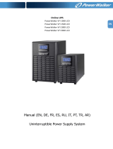
2-1. Rear panel view
6kVA
Schuko Type
1. Output receptacles
2. AC input
3. Circuit breaker for output receptacles
4. External battery connection (only available for L model)
5. Intelligent slot
6. Output terminal
7. Modem/Phone line/Network surge protection
2-2. Setup the UPS
Step 1: UPS input connection
Plug the UPS into a two-pole, three-wire, and grounded receptacle only. Please do not use
extension cords. The input plug is #12*3C.

Step 2: UPS output connection
Simply plug devices to output sockets. During power failure, UPS will provide power to
connected devices.
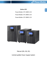
Step 3: Communication connection
Intelligent slot
This model is equipped with intelligent slot perfect for SNMP, RS-232, USB or AS-400 card.
When installing with these communication card in the UPS, it will provide advanced
communication and monitoring options.
Step 1:
Step 2:
Step 3:
Remove cover of intelligent
slot.
Insert communication card
into the slot
Screw card tightly and
complete installation.
Step 4: Turn on the UPS
Press the ON/Mute button on the front panel for two seconds to power on the UPS.
Note: The battery charges fully during the first five hours of normal operation. Do not
expect full battery run capability during this initial charge period.
Step 5: Install software
For optimal computer system protection, install UPS monitoring software to fully configure UPS
shutdown. You may insert provided CD into CD-ROM to install the monitoring software. If not,
please follow steps below to download and install monitoring software from the internet:
1. Go to the website http://www.power-software-download.com
2. Click ViewPower software icon and then choose your required OS to download the software.
3. Follow the on-screen instructions to install the software.
4. When your computer restarts, the monitoring software will appear as an orange plug icon
located in the system tray, near the clock.
Step 6: External battery connection
Follow the below chart to make external battery connection.
To external
battery

3. Operations
3-1. Button operation
Button
Function
ON/Mute Button
Turn on the UPS: Press and hold ON/Mute button for at least 2
seconds to turn on the UPS.
Mute the alarm: After the UPS is turned on in battery mode, press
and hold this button for at least 5 seconds to disable or enable the
alarm system. But it’s not applied to the situations when warnings or
errors occur.
Down key: Press this button to display previous selection in UPS
setting mode.
Switch to UPS self-test mode: Press ON/Mute buttons simultaneously
for 5 seconds to enter UPS self-testing while in AC mode.
OFF/Enter Button
Turn off the UPS: Press and hold this button at least 2 seconds to turn
off the UPS in battery mode. UPS will be in standby mode under
power normal or transfer to Bypass mode if the Bypass enable setting
by pressing this button.
Confirm selection key: Press this button to confirm selection in UPS
setting mode.
Select Button
Switch LCD message: Press this button to change the LCD message
for input voltage, input frequency, battery voltage, output voltage
and output frequency. It will return back to default display when
pausing for 10 seconds.
Setting mode: Press and hold this button for 5 seconds to enter UPS
setting mode when UPS is in standby mode or bypass mode.
Up key: Press this button to display next selection in UPS setting
mode.
ON/Mute + Select
Button
Switch to bypass mode: When the main power is normal, press
ON/Mute and Select buttons simultaneously for 5 seconds. Then UPS
will enter to bypass mode. This action will be ineffective when the
input voltage is out of acceptable range.
3-2. LCD Panel

Display
Function
Backup time information
Indicates the remaining backup time in pie chart.
Indicates the remaining backup time in numbers.
H: hours, M: minute, S: second
Fault information
Indicates that the warning and fault occurs.
Indicates the warning and fault codes, and the codes are listed in
details in 3-5 section.
Mute operation
Indicates that the UPS alarm is disabled.
Output & Battery voltage information
Indicates the output voltage, frequency or battery voltage.
Vac: output voltage, Vdc: battery voltage, Hz: frequency
Load information
Indicates the load level by 0-25%, 26-50%, 51-75%, and
76-100%.
Indicates overload.
Indicates the load or the UPS output is short circuit.
Mode operation information
Indicates the UPS connects to the mains.
Indicates the battery is working.
Indicates the bypass circuit is working.
Indicates the ECO mode is enabled.
Indicates the Inverter circuit is working.
Indicates the output is working.
Battery information
Indicates the Battery level by 0-25%, 26-50%, 51-75%, and
76-100%.
Indicates the battery is fault.
Indicates low battery level and low battery voltage.
Input & Battery voltage information
Indicates the input voltage or frequency or battery voltage.
Vac: Input voltage, Vdc: battery voltage, Hz: input frequency

3-3. Audible Alarm
Battery Mode
Sounding every 4 seconds
Low Battery
Sounding every second
Overload
Sounding twice every second
Fault
Continuously sounding
Bypass Mode
Sounding every 10 seconds
3-4. LCD display wordings index
Abbreviation
Display content
Meaning
ENA
Enable
DIS
Disable
ESC
Escape
HLS
High loss
LLS
Low loss
BAT
Battery
TP
Temperature
CH
Charger
3-5. UPS Setting
There are three parameters to set up the
UPS.
Parameter 1: It’s for program
alternatives. There are 6 programs to set
up. Refer to below table.
Parameter 2 and parameter 3 are the
setting options or values for each
program.
Parameter 1
Parameter 2
Parameter 3

01: Output voltage setting
Interface
Setting
Parameter 3: Output voltage
For 208/220/230/240 VAC models, you may choose the
following output voltage:
208: presents output voltage is 208Vac
220: presents output voltage is 220Vac
230: presents output voltage is 230Vac
240: presents output voltage is 240Vac
For 104/110/115/120 VAC models, you may choose the
following output voltage:
104: presents output voltage is 104Vac
110: presents output voltage is 110Vac
115: presents output voltage is 115Vac
120: presents output voltage is 120Vac
02: Output frequency setting
Interface
Setting
Parameter 2 & 3: Output frequency setting.
You may set the initial frequency in battery mode:
BAT 50: output frequency is set in 50Hz
BAT 60: output frequency is set in 60Hz
If converter mode is enabled, you may choose the
following output frequency:
CF 50: output frequency is set in 50Hz
CF 60: output frequency is set in 60Hz
03: ECO mode enable/disable
Interface
Setting
Parameter 3: Enable or disable ECO function. You may
choose the following two options:
ENA: ECO mode is enabled
DIS: ECO mode is disabled
04: ECO voltage range setting
Interface
Setting
Parameter 2 & 3: Set the acceptable high voltage point
and low voltage point for ECO mode by pressing Down key
or Up key.
HLS: High loss voltage in ECO mode in parameter 2.
The setting range in parameter 3 is from +7V to +24V of
the nominal voltage.
LLS: Low loss voltage in ECO mode in parameter 2.
The setting range in parameter 3 is from -7V to -24V of the
nominal voltage.

05: Bypass function enable/disable when UPS is off
Interface
Setting
Parameter 3: Enable or disable Bypass function. You may
choose the following two options:
ENA: Bypass enable
DIS: Bypass disable
06: Bypass voltage range setting
Interface
Setting
Parameter 2 & 3: Set the acceptable high voltage point
and acceptable low voltage point for Bypass mode by
pressing the Down key or Up key.
HLS: Bypass high voltage point:
230-264: setting the high voltage point in parameter 3
from 230Vac to 264Vac.
LLS: Bypass low voltage point:
187-220: setting the low voltage point in parameter 3
from 187Vac to 220Vac
07: Input voltage range setting
Interface
Setting
Parameter 2 & 3: Set the acceptable input voltage range
for AC mode by pressing the Down key or Up key.
HLS: Acceptable maximum input voltage point:
280/270/260: selecting 280Vac, 270Vac, or 260Vac as
the maximum input voltage point in parameter 3.
LLS: Acceptable minimum input voltage point:
175/185/195: selecting 175Vac, 185Vac, or 195Vac as
the minimum input voltage point in parameter 3.
00: Exit setting

3-6. Operating Mode Description
Operating mode
Description
LCD display
Online mode
When the input voltage is within
acceptable range, UPS will provide pure
and stable AC power to output. The UPS
will also charge the battery at online
mode.
ECO mode
Energy saving mode:
When the input voltage is within voltage
regulation range, UPS will bypass
voltage to output for energy saving.
Battery mode
When the input voltage is beyond the
acceptable range or power failure and
alarm is sounding every 4 second, UPS
will backup power from battery.
Bypass mode
When input voltage is within acceptable
range but UPS is overload, UPS will enter
bypass mode or bypass mode can be set
by front panel. Alarm is sounding every
10 second.
Standby mode
UPS is powered off and no output supply
power, but still can charge batteries.
3-7. Faults Reference Code
Fault event
Fault code
Icon
Fault event
Fault code
Icon
Bus start fail
01
x
Inverter voltage Low
13
x
Bus over
02
x
Inverter output short
14
Bus under
03
x
Battery voltage too high
27
Bus unbalance
04
x
Battery voltage too low
28
Inverter soft start fail
11
x
Over temperature
41
x
Inverter voltage high
12
x
Over load
43

3-8. Warning indicator
Warning
Icon (flashing)
Alarm
Low Battery
Sounding every second
Overload
Sounding twice every second
Battery is not connected
Sounding every second
Over Charge
Sounding every second
Site wiring fault
Sounding every second
Over temperature
Sounding every second
Charger failure
Sounding every second
Out of bypass voltage range
Sounding every second

4. Troubleshooting
If the UPS system does not operate correctly, please solve the problem by using the table
below.
Symptom
Possible cause
Remedy
No indication and alarm even
though the mains is normal.
The AC input power is not
connected well.
Check if input power cord
firmly connected to the
mains.
The AC input is connected
to the UPS output.
Plug AC input power cord
to AC input correctly.
The icon and flashing on
LCD display and alarm is sounding
every second.
Line and neutral
conductors of UPS input
are reversed.
Rotate mains power socket
by 180° and then connect
to UPS system.
The icon and flashing
on LCD display and alarm is
sounding every second.
The external or internal
battery is incorrectly
connected.
Check if all batteries are
connected well.
Fault code is shown as 27 and the
icon is lighting on LCD
display and alarm is continuously
sounding.
Battery voltage is too high
or the charger is fault.
Contact your dealer.
Fault code is shown as 28 and the
icon is lighting on LCD
display and alarm is continuously
sounding.
Battery voltage is too low
or the charger is fault.
Contact your dealer.
The icon and is
flashing on LCD display and alarm
is sounding twice every second.
UPS is overload
Remove excess loads from
UPS output.
UPS is overloaded. Devices
connected to the UPS are
fed directly by the
electrical network via the
Bypass.
Remove excess loads from
UPS output.
After repetitive overloads,
the UPS is locked in the
Bypass mode. Connected
devices are fed directly by
the mains.
Remove excess loads from
UPS output first. Then shut
down the UPS and restart
it.
Fault code is shown as 43 and The
icon is lighting on LCD
display and alarm is continuously
sounding.
The UPS shut down
automatically because of
overload at the UPS
output.
Remove excess loads from
UPS output and restart it.
Fault code is shown as 14 and the
icon is lighting on LCD
display and alarm is continuously
sounding.
The UPS shut down
automatically because
short circuit occurs on the
UPS output.
Check output wiring and if
connected devices are in
short circuit status.

Symptom
Possible cause
Remedy
Fault code is shown as 1, 2, 3, 4,
11, 12, 13 and 41 on LCD display
and alarm is continuously
sounding.
A UPS internal fault has
occurred. There are two
possible results:
1. The load is still supplied,
but directly from AC power
via bypass.
2. The load is no longer
supplied by power.
Contact your dealer
Battery backup time is shorter
than nominal value
Batteries are not fully
charged
Charge the batteries for at
least 5 hours and then
check capacity. If the
problem still persists,
consult your dealer.
Batteries defect
Contact your dealer to
replace the battery.

5. Storage and Maintenance
Operation
The UPS system contains no user-serviceable parts. If the battery service life (3~5 years
at 25°C ambient temperature) has been exceeded, the batteries must be replaced. In this
case, please contact your dealer.
Storage
Before storing, charge the UPS 5 hours. Store the UPS covered and upright in a cool, dry
location. During storage, recharge the battery in accordance with the following table:
Storage Temperature
Recharge Frequency
Charging Duration
-25°C - 40°C
Every 3 months
1-2 hours
40°C - 45°C
Every 2 months
1-2 hours
Be sure to deliver the spent battery to a recycling facility or ship it to your
dealer in the replacement battery packing material.

6. Specifications
MODEL
Newtech ECO 6kVA
CAPACITY
6000VA/4200W
INPUT
Voltage
Range
Low Line Transfer
175 VAC / 150 VAC / 130 VAC / 110 VAC ± 5 %
( based on load percentage 100%-80% / 80% - 70% / 70%- 60% / 60% - 0)
Low Line Comeback
183 VAC / 158 VAC / 138 VAC / 118 VAC ± 5 %
( based on load percentage 100%-80% / 80% - 70% / 70%- 60% / 60% - 0)
Low Line Comeback
(Auto restart)
183VAC ± 5 % (80%~100% Load)
158VAC ± 5 % ( 0%~ 80% Load)
High Line Transfer
280 VAC ± 5 %
High Line Comeback
270 VAC ± 5 %
Frequency Range
40Hz ~ 70 Hz
Phase
Single phase with ground
Power Factor
≧ 0.95
OUTPUT
Output voltage
208/220/230/240VAC
AC Voltage Regulation
(Batt. Mode)
± 3%
Frequency Range
(Synchronized Range)
47~53 Hz or 57 ~ 63 Hz
Frequency Range (Batt. Mode)
50 Hz ± 0.25 Hz or 60Hz ± 0.3 Hz
Overload
100%-110%: 10 Minutes, sounding every 0.5 seconds
110%-130%: 30 Seconds, sounding every 0.5 seconds
>130% : 1.5 Seconds, sounding every 0.5 seconds
Current Crest Ratio
3:1
Harmonic Distortion
≦ 3 % THD (Linear Load)
≦ 6 % THD (Non-linear Load)
Transfer
Time
AC Mode to Batt. Mode
Zero
Inverter to Bypass
4 ms (Typical)
Waveform (Batt. Mode)
Pure Sinewave
PEAK EFFICIENCY
AC Mode
90%
Battery Mode
85%
BATTERY
Standard
Model
Battery Type
12V/10AH
Numbers
8
Recharge Time (Typical)
8 hours recover to 90% capacity
Charging Current
1A
Boost Voltage
113.3V ± 1%
Floating Voltage
109.4 ± 1%
PHYSICAL
Standard
Model
Dimension, D X W X H
426 X 190 X 318
Net Weight (kgs)
35.3
ENVIRONMENT
Operation Humidity
0-95 % RH @ 0- 40°C (non-condensing)
Noise Level
Less than 55dBA @ 1 Meter
MANAGEMENT
Optional RS-232 or USB
Supports Windows 2000/2003/XP/Vista/2008/XP/7, Linux, Unix, and MAC
Optional SNMP
Power management from SNMP manager and web browser
* Derate capacity to 60% of capacity in Frequency converter mode and to 80% when the output voltage is adjusted to 208VAC
(104VAC).
/