Page is loading ...

Form No. 70069A 7/99 Clarke Technology Printed in the U.S.A.
READ THIS BOOK
This book has important information for the use and safe operation of this machine. Failure to read
this book prior to operating or attempting any service or maintenance procedure to your ALTO
machine could result in injury to you or to other personnel; damage to the machine or to other property
could occur as well. You must have training in the operation of this machine before using it. If
operator(s) cannot read English, have this manual explained fully before attempting to operate this
machine.
All directions given in this book are as seen from the operator’s position at the rear of the machine.
For new books write to: ALTO U.S. Inc., 2100 Highway 265, Springdale, Arkansas 72764.
Operating
Instructions
Instrucciones
De Operacion
Instructions
D'Operation
530 / 530cc
Upright
Vacuum
Barredoras
Verticales
Balayeuse
E

Page -2- CLARKE TECHNOLOGY 530 Upright Vacuum Operator's Manual
Table of Contents
Important Safety Instructions .................................................................................. 5
Grounding Instructions ............................................................................................ 8
General Diagram and Parts List ............................................................................. 10
How To Assemble ................................................................................................... 11
How To Use ............................................................................................................ 14
Height Adjustment ................................................................................................... 14
How To Change Disposable Paper Bag .................................................................. 16
How To Clean Permanent Bag ................................................................................ 16
How To Replace Brush Roll Belt ............................................................................. 18
How To Replace Motor ........................................................................................... 20

Page -5-
CLARKE TECHNOLOGY 530 Upright Vacuum Operator's Manual
IMPORTANT SAFETY INSTRUCTIONS
WHEN USING AN ELECTRICAL UPRIGHT VACUUM CLEANER, BASIC PRECAUTIONS SHOULD BE
FOLLOWED, INCLUDING THE FOLLOWING:
READ ALL INSTRUCTIONS BEFORE USING VACUUM CLEANER.
SAVE THESE INSTRUCTIONS FOR FUTURE REFERENCE.
WARNING: To reduce the risk of fire, electric shock, or injury:
1. Do not use outdoors or on wet surfaces.
2. Do not leave vacuum cleaner unattended when plugged in. Turn off the switch and unplug the
electrical cord when not in use and before servicing.
3. Do not allow to be used as a toy. Close attention is necessary when used by or near
children.
4. Use only as described in this manual. Use only manufacturer's recommended attachments.
5. Do not use with damaged cord or plug. If vacuum cleaner is not working as it should, has
been dropped, damaged, left outdoors, or dropped into water, return it to a service center
before using.
6. Do not pull or carry by cord, use cord as a handle, close a door on cord, or pull a cord around
sharp edges or corners. Do not run vacuum cleaner over cord. Keep cord away from heated
surfaces.
7. Do not use extension cords or outlets with inadequate current carrying capacity.
8. Turn off all controls before unplugging.
9. Do not handle plug or vacuum cleaner with wet hands.
10. Do not put any objects into openings. Do not use with any opening blocked, keep free of
dust, lint, hair, and anything that may reduce airflow.
11. This vacuum cleaner creates suction and contains a revolving brush roll. Keep hair, loose
clothing, fingers and all parts of body away from openings and moving parts.
12. Do not pick up anything that is burning or smoking, such as cigarettes, matches or hot
ashes.
13. Do not use without dust bag in place.
14. Use extra care when cleaning on stairs.
15. Do not use to pick up flammable or combustible liquids such as gasoline, or use in areas
where they may be present.
16. Store your cleaner indoors in a cool, dry area.
17. Do not unplug by pulling on cord. To unplug, grasp the plug, NOT THE CORD.
This machine is intended for commercial use.

Page -8- CLARKE TECHNOLOGY 530 Upright Vacuum Operator's Manual
INSTRUCCIONES PARA LA CONEXION
ELECTRICA DE LA MAQUINA
La máquina debe ser puesta a tierra. En caso de mal
funcionamiento o de avería, el hilo de tierra es un camino de
menor resistencia que permite el paso de corriente ; por lo
cual se reduce el riesgo de choque eléctrico. La máquina
tiene un cable de alimentación con tres cordones y un
enchufe con tres clavijas de las cuales una está puesta a
tierra. El enchufe sólo puede ser conectado con una caja de
enchufe reglamentaria, puesta a tierra con todas las reglas
del arte y conforme a los reglamentos locales.
AVISO: Una conexión incorrecta del
conductor de puesta a tierra puede causar un
choque eléctrico. Acuda a un técnico
autorizado o a un electricista si tiene alguna
duda acerca de la puesta a tierra correcta de su
caja de enchufe. Nunca modifique el enchufe
suministrado con la máquina. Si no encaja el
enchufe en la caja de enchufe, haga cambiar su
caja de enchufe por un electricista autorizado.
La máquina se concibió para funcionar en un circuito de
potencia nominal de 220 V. Tiene un enchufe con puesta a
tierra semejante al enchufe reproducido en el esquema A de
la figura 2. Compruebe que la máquina esté conectada con
una caja de enchufe que tiene la configuración adecuada.
No utilice ningún adaptador para conectar esta máquina.
GROUNDING INSTRUCTIONS
This appliance must be grounded. If it should malfunction or
breakdown, grounding provides a path of least resisitance for
electric current to reduce the risk of electric shock. This
appliance is equipped with a cord having an equipment-
grounding conductor and grounding plug. The plug must be
plugged into an appropriate outlet that is properly installed
and grounded in accordance with all local codes and ordi-
nances.
WARNING: Improper connection of the
equipment-grounding conductor can result in risk of
electric shock. Check with a qualified electrician or
service person if you are in doubt as to whether the
outlet is properly grounded. Do not modify the plug
provided with the appliance - if it will not fit the
outlet, have a proper outlet installed by a qualified
electrician.
This appliance is for use on a nominal 120-volt circuit and
has a ground plug that looks like the plug illustrated in figure
1. Make sure that the appliance is connected to an outlet
having the same configuration as the plug. No adapter
should be used with this appliance.
Grounding
Pin
Grounded
Outlet
Grounded
Outlet
Box
Fig. 1
Terminal de
tierra.
Toma
corriente
con polo
de tierra.
Tapa del toma
corriente con
polo de tierra
Fig. 2

Page -10- CLARKE TECHNOLOGY 530 Upright Vacuum Operator's Manual
GENERAL DIAGRAM DIAGRAMA GENERAL DIAGRAMME GENERALE
1. Cord Hook
2. Upper Handle Tube
3. Nut & Bolt
4. Lower Handle Tube
5. Nut & Bolt
6. Height Adjustment
7. Bag Inlet
8. Bag Support
9. Handle Release Pedal
10. Bag
11. Spring Bag Hook
12. 35 Foot Line Cord
13. 3 Wire Grounded Plug
1. Gancho del cordón
2. Tubo superior de la manija
3. Tornillo y tuerca
4. Tubo inferior de la manija
5. Tornillo y tuerca
6. Ajuste de altura
7. Entrada de la bolsa
8. Soporte de la bolsa
9. Pedal retén manija
10. Bolsa
11. Sostén de la bolsa
12. Cable de 11 metros
13. Clavija aterrizada
1. Crochet pour le cordon
2. Tube supérieur de la poignée
3. Vis et écrou
4. Tube inférieur de la poignée
5. Vis et écrou
6. Réglage de la hauteur
7. Entrée du sac
8. Support du sac
9. Pédale suport poignée
10. Sac
11. Support du sac
12. Cable de 11 meters
13. Broche de mise a la terre
PARTS LIST LISTA DE PARTES LISTE DES PIECES
1
12
13
2
4
5
6
11
3
10
8
7
9

Page -11-
CLARKE TECHNOLOGY 530 Upright Vacuum Operator's Manual
HOW TO ASSEMBLE
CAUTION: Fully assemble the unit before
using.
Hardware Package: The package contains two nuts
and bolts, one screw and one spring.
1. Assemble Lower Handle
Attach lower handle over socket, align holes and
fasten with bolt and internally threaded nut provided
in hardware package.
2. Attach Upper Handle
Place upper handle over lower handle align holes
and fasten with bolt and internally threaded nut
included in hardware package.
3. Install Line Cord Support and Bag Hook
Attach spring bag hook to rear upper handle tube.
Insert fitting end into rectangular hole. Align holes
and fasten with screw provided in hardware pack-
age.
4. Bag Assembly (OPTIONAL ACCESSORY)
Open zipper of paper bag cover. Attach spring
around dust bag connector located inside paper bag
cover (see figure 4). Slide paper bag tube over
connector and roll spring up to hold bag. Be sure
zipper printing on paper aligns up with zipper on
paper bag cover. Hold paper bag cover on back of
the unit with printing facing handle tube.
5. Install Bag to Upright Vacuum
Slide lower bag support into slots of bag support
guide, pressing right. Push bag support towards
inlet and turn knob clockwise. Insert top spring into
hook (see figure 5).
Figure 4
Figure 5
Top Spring
Paper Bag
Cover
Paper Bag
Tube
Spring
Lower Bag Support
Dust Bag
Connector
Line Cord
Support
and Bag
Hook
Bag
Support
Guide
Knob

Page -14- CLARKE TECHNOLOGY 530 Upright Vacuum Operator's Manual
HOW TO USE
(See Fig. 10)
1. Remove electrical cord from hook and plug into
electrical outlet.
2. Slide height adjustment to the desired setting.
3. Press the handle release pedal and pull the handle
to the desired position, the unit will turn on auto-
matically when handle is pulled down. To clean
under, press the pedal again and lower the handle.
4. Vacuum slowly with forward and backward strokes,
covering small areas at a time. The time required to
clean the carpet will depend on type of carpet and
amount of dirt.
5. The unit will turn off automatically when the handle
is returned to the vertical position.
Fig. 10
Fig. 11
HEIGHT ADJUSTMENT
The front of the cleaner has a continuous height
adjustment which raises or lowers the cleaner base to
match the type of carpet. With the cleaner cord
unplugged, set the adjustment according to your
specific needs (Fig. 11).
While the cleaner is off and disconnected from the
outlet, tilt the cleaner back to remove weight from the
front wheels, and adjust the setting.
Plug the cleaner into electrical outlet, press the handle
release, lower handle and pass the cleaner over the
carpet. If the cleaner is difficult to push, follow the
procedure and test the cleaner at the next height
setting until the unit is comfortable to move. the brush
roll must make contact with the carpet for effective
cleaning.
Store
Apagado
Éteint
Operate
En operacion
En marche
Clean under
Aspirado por debajo
Aspiration en dessous
Height Adjustment
Adjuste de altura
Réglage de la hauteur

Page -16- CLARKE TECHNOLOGY 530 Upright Vacuum Operator's Manual
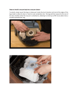
HOW TO CHANGE DISPOSABLE PAPER BAG
How to Change Disposable Paper Bag (Optional
Accessory - See page 7, #4)
Disconnect unit from electrical outlet before changing
bag.
Change the dust bag frequently. Some fine particles
can restrict airflow very quickly and will decrease
performance even before the bag appears to be full.
For that reason, when vacuuming carpet freshners or
cleaners, powder, plastic dust, or similar fine sub-
stances, the bag may need to be changed more often.
1. Unzip the paper bag cover. Roll spring down to
release paper bag tube from dust bag connector.
2. Put a new paper bag in the vacuum cleaner. Slide
paper bag tube over connector and roll spring up to
hold bag. Be sure zipper printing on paper aligns-up
with zipper on paper bag cover. Tuck dust bag into
permanent bag. Make sure dust bag is fully
extended in the bag cover, zip the bag cover.
CAUTION: Be sure to clean impeller chamber every
time you change the disposable paper
bag. Do not attempt to empty and
reuse your paper bag when full, always
replace it with a new one.
HOW TO CLEAN PERMANENT BAG
Disconnect unit from electrical outlet before cleaning
bag.
1. Un hook spring from hook.
2. Turn knob and release bag support from bag support
guide.
3. Release bag closing clip from Permanent Bag. Still
holding the bag, put the opening in a plastic bag and
shake well to empty it.
4. Insert bag closing clip to Permanent Bag.
5. Hold Permanent Bag on back of unit with printing
facing handle tube. Slide lower bag support into
slots of bag support guide. Push bag support
towards inlet and turn knob to fasten. Insert Spring
onto hook.
CAUTION: Be sure to clean fan chamber every time
you empty permanent bag.

Page -18- CLARKE TECHNOLOGY 530 Upright Vacuum Operator's Manual
HOW TO REPLACE BRUSH ROLL BELT
NOTE: Turn off the switch and unplug the electrical
cord before replacing belt. Belt can become hot during
normal use. To prevent injury, avoid touching the belt
and motor nut when it is hot.
CAUTION: Improper installation of the brush roll or
brush roll belt could cause carpet
cleaner damage.
1. Push handle release and lower handle; push the
height setting to th lowest position. Turn the
vacuum cleaner so the underneath side and brush
roll face toward you. (Fig. 12)
2. Remover retainer bar by pushing downward on the
right end, until it unhooks. Release other end.
CAUTION: While pushing one end of retainer bar,
hold the machine down to avoid tilting.
3. Remove bottom plate and fan cover by lifting off from
motor. (Fig. 13)
4. Remove belt from motor nut. Pull brush roll up,
remove belt from brush roll and change with a new
belt.
5. Insert brush roll making sure the tabs on the edge of
bearing support are facing upward. Bristles on
brush roll must form a "V" facing toward you.
6. Twist the belt towards the right and place around
motor nut. The higher end of the belt must be on
the right side, and the lower end on the left side, as
shown in the drawing below (Fig. 14). Rotate brush
to ensure belt is positioned correctly.
Fig. 12
Fig. 13
Fig. 14
Retainer Bar
Varilla reten
Corde á piano
Fan Cover
Cubierta del
ventilador
Couvercle du
ventilateur
Bottom Plate
Tapa Rodillo
Cache rouleau
Brush Roll
Cepillo Giratorio
Brosse tournante
Motor Cover
Cubierta del
motor
Couvercle du
moteur
Motor Nut
Tuerca del
ventilador
É crou du
moteur
Belt
Banda
Courroie
Low side of belt
Posicion baja de la
banda
Position basse de la
courroie
High side of belt
Posicion alta de la
banda
Position haute de la
courroie

Page -20- CLARKE TECHNOLOGY 530 Upright Vacuum Operator's Manual
HOW TO REPLACE MOTOR
IMPORTANT: Disconnect machine before replacing
motor.
1. Detach bag (1).
2. Remove screw (2) and nut (3) at bottom of handle
tube.
3. Press the handle release pedal (9) and pull handle
down to horizontal position.
4. Remove handle tube from socket.
5. Remove screw (6).
6. Remove height adjustment knob (7).
7. Turn machine upside down.
8. Remove cover springs (8).
9. Remove retainer bar (19).
10. Remove bottom plate (10).
11. Remove fan cover (11).
12. Remove band (12).
13. Hold vacuum cleaner from the motor cover and turn
to the upright position. Remove motor cover.
14. Remove tunnels from motor (13, 14).
15. Remove screws (15, 16, 17, 18).
16. Disconnect cord from switch.
17. Disconnect connector.
18. Remove motor (fig. 11).
19. Replace new motor.
To assemble machine, follow above steps in a reverse
order.
Fig. 15
Fig. 16
4
1
5
6
7
3
2
9
8
15
16
14
13
18
17
12
11
19
10

ALTO
®
PRODUCT SUPPORT BRANCHES
PRODUCTION FACILITIES
ALTO Danmark A/S, Aalborg
Blytaekkervej 2
DK-9000 Aalborg
+45 72 18 21 00
ALTO Danmark A/S, Hadsund
Industrikvarteret
DK-9560 Hadsund
+45 72 18 21 00
SALES SUBSIDIARIES
ALTO Canada Ltd., Rexdale Ontario
24 Constellation Ct.
(416) 675-5830
ALTO Overseas Inc., Sydney (Australia)
1B/8 Resolution Drive
Caringbah NSW 2229
+61 2 9524 6122
ALTO Cleaning Systems Asia Pte Ltd., Singapore
No. 17 Link Road
Singapore 619034
+65 268 1006
ALTO Deutschland GmbH, Bellenberg (Germany)
Guido-Oberdorfer-Straße 2-8
89287 Bellenberg
+49 0180 5 37 37 37
ALTO Cleaning Systems (UK) Ltd., Penrith
Gilwilly Industrial Estate
Penrith
Cumbria CA11 9BN
+44 1768 868 995
ALTO France S.A. Strasbourg
B.P. 44, 4 Place d’Ostwald
F-67036 Strasbourg
Cedex 2
+33 3 8828 8400
ALTO Nederland B.V. Vianen
Stuartweg 4C
NL-4131 NJ Vianen
+31 347 324000
ALTO Sverige AB, Molndal (Sweden)
Aminogatan 18
Box 4029
S-431 04 Molndal
+46 31 706 73 00
ALTO Norge A/S, Oslo (Norway)
Bjornerudveien 24
N-1266
+47 2275 1770
CLARKE TECHNOLOGY
AMERICAN SANDERS TECHNOLOGY
A.L. COOK TECHNOLOGY
Customer Service Headquarters and Factory
2100 Highway 265
Springdale, Arkansas 72764
(501) 750-1000
Technical Service
1-800-356-7274
U. S. A. Locations European Locations
HEAD OFFICE
ALTO U.S. Inc., St. Louis, Missouri
16253 Swingley Ridge Road, Suite 200
Chesterfield, Missouri 63017-1725
PRODUCTION FACILITIES
ALTO U.S. Inc., Springdale, Arkansas
2100 Highway 265
Springdale, Arkansas 72764
(501) 750-1000
Customer Service - 1-800-253-0367
Technical Service - 1-800-356-7274
ALTO U.S. Inc., Bowling Green, Ohio 43402
1100 Haskins
SERVICE FACILITIES
ALTO U.S. Inc., Carlstadt, New Jersey 07072
150 Commerce Road
(201) 460-4774
ALTO U.S. Inc., Elk Grove, Illinois 60007
2280 Elmhurst Road
(847) 956-7900
ALTO U.S. Inc., Denver, Colorado 80204
1955 West 13th Ave.
(303) 623-4367
ALTO U.S. Inc., Houston, Texas 77040
7215 North Gessner Road
SALES AND SERVICE FACILITIES
ALTO U.S. Inc., Madison Heights, Michigan 48071-0158
29815 John R.
(810) 544-6300
ALTO U.S. Inc., Marietta, Georgia 30062
1355 West Oak Common Lane
(770) 973-5225

CLARKE TECHNOLOGY WARRANTY
This Clarke Technology Industrial/Commercial Product is warranted to be free from defects in materials and
workmanship under normal use and service for a period of one year from the date of purchase, when operated and
maintained in accordance with Clarke Technology's Maintenance and Operations instructions.
This warranty is extended only to the original purchaser for use of the product. It does not cover normal
wear parts such as electrical cable, rubber parts, hoses and motor brushes.
If difficulty develops with the product, you should:
(a). Contact the nearest authorized Clarke Technology repair location or contact the Clarke Technology Service
Operations Department, 2100 Highway 265, Springdale, Arkansas 72764, for the nearest authorized Clarke Tech-
nology repair location. Only these locations are authorized to make repairs to the product under this warranty.
(b). Return the product to the nearest Clarke Technology repair location. Transportation charges to and from the
repair location must be prepaid by the purchaser.
(c). Clarke Technology will repair the product and or replace any defective parts without charge within a reason-
able time after receipt of the product.
Clarke Technology's liability under this warranty is limited to repair of the product and/or replacement of parts
and is given to purchaser in lieu of all other remedies, including INCIDENTAL AND CONSEQUENTIAL DAMAGES.
THERE ARE NO EXPRESS WARRANTIES OTHER THAN THOSE SPECIFIED HEREIN. THERE ARE NO
WARRANTIES WHICH EXTEND BEYOND THE DESCRIPTION OF THE FACE HEREOF. NO WARRANTIES,
INCLUDING BUT NOT LIMITED TO WARRANTY OF MECHANTABILITY, SHALL BE IMPLIED. A warranty
registration card is provided with your Clarke Technology product. Return the card to assist Clarke Technology in
providing the performance you expect from your new floor machine.
ALTO U.S. Inc., 2100 Highway 265, Springdale, Arkansas 72764.
CLARKE TECHNOLOGY reserves the right to make
changes or improvements to its machine without notice.
Always use genuine Clarke Technology Parts for repair.
CLARKE TECHNOLOGY
2100 Highway 265
Springdale, Arkansas, 72764

Form No. 70070A 7/99 Clarke Technology Printed in the U.S.A.
READ THIS BOOK
This book has important information for the use and safe operation of this machine. Failure to read
this book prior to operating or attempting any service or maintenance procedure to your ALTO machine
could result in injury to you or to other personnel; damage to the machine or to other property could
occur as well. You must have training in the operation of this machine before using it. If operator(s)
cannot read English, have this manual explained fully before attempting to operate this machine.
All directions given in this book are as seen from the operator’s position at the rear of the machine.
For new books write to: ALTO U.S. Inc., 2100 Highway 265, Springdale, Arkansas 72764.
Repair Parts
List
530 / 530cc
Upright Vacuum

Page -2- CLARKE TECHNOLOGY 530 Upright Vacuum Operator's Manual
Table of Contents
Final Test for Product Safety .................................................................................. 3
Replacement Procedures ....................................................................................... 3
To Disassemble the Motor ...................................................................................... 4
530 Upright Vacuum External Parts ........................................................................ 5
530 Upright Vacuum Internal Parts ......................................................................... 6
530 Upright Motor Assembly................................................................................... 8
Trouble Shooting Guide .......................................................................................... 9
Wiring Diagram ....................................................................................................... 9
530cc Drawing Assembly and Parts List ................................................................. 10

Page -3-
CLARKE TECHNOLOGY 539 Upright Vacuum Operator's Manual
FINAL TEST FOR PRODUCT SAFETY
At the completion of any repairs the product should be
electrically tested for running and electric strength as
follows:
Electric Strength
1. Set hi-pot test meter to 1500 volts.
2. Product switch to ON-position.
3. Touch one probe of tester to one blade of power
cord plug and touch other probe to handle tube.
There should be no breakdown.
Running
Run the machine with the height adjustment knob on
high and check:
1. There should be no abnormal noise or vibration.
2. The carbon brushes spark should be small and
uniform.
3. The current should not exceed 9.0 amps.
NOTE: The letters with the item no., references,
identify item number on internal (I), external (E) or
motor (M) illustrations.
REPLACEMENT PROCEDURES
1. To Remove Bag (30-E).
Release Spring (36-E) from handle, turn knob on
bag coupling ccw (25-E), slide coupling off unit.
2. To Remove Handle Tube (7-E, 10-E).
a. Disengage line cord from line cord retainer (3E)
pulling cord outward from retainer bottom.
b. Remove bolt and nut (8E and 9E) on handle
socket (24-I) and pull tube out.
3. To Replace The Belt (39-I)
a. Place upright on hood so wheels face upward.
Make sure to place on protected surface not to
damage hood.
b. Remove retaining bar (58-I) by pressing down
on right side (longest), remove brush roll cover
(57-I) and fan cover (38-I).
c. Stretch and twist belt over motor pulley (15-M)
to pull it out. (If not broken).
d. Remove complete brush roll (52-I) with bearing
supports (54-I) pulling it out near the bearings.
e. Place new belt on roll, replace roll on chassis
making sure the mark "top" on bearings
support faces towards the brush roll cover and
reassemble.
4. To Replace the Brush Roll (52-I) or Bearing
Supports (54-I).
a. Follow steps indicated on point 3a and 3b.
b. Remove bearing support (54-I) pulling them
away from brush roll (old or new).
c. Place bearing supports on new brush roll, place
belt over roll and replace it on chassis following
steps 3e.
5. To Replace Rear Wheels (16-I).
a. Remove hood as in step 7.
b. Pull out retainer pin (19-I) from axle, and slide
wheels outward.
c. Replace the new wheel and axle, and insert the
pin.
d. Replace hood.
6. To Replace Front Wheels (42-E).
a. Remove hood as in step 7.
b. Remove screws (44-I) from front axle supports
(45-I) and take out axle assembly.
c. Remove cotter pin (43-E) and flat washer (59-I)
and pull out wheel.
d. Replace the new front wheel, washer and cotter
pin.
e. Replace axle assembly on chassis making
sure springs (51 and 47-I) are in place.
f. Replace hood.
7. To Remove the Hood (17-E).
a. Remove bag and handle tube as in steps 1 and
2.
b. Depress handle release pedal (31-I) and rotate
socket (24-I) to horizontal position.
c. Remove screw from height adjustment knob
(11-E) and pull out knob (12-E).
d. Place upright on hood so wheels face upward,
make sure to place on protected surface not to
damage hood.
e. Remove springs (18-E) from "V" tabs on
chassis, turn upright holding hood and separate
hood from chassis.
8. To Replace Motor (3-I).
a. Remove belt as in steps 3a to 3c.
b. Remove hood as in step 7.
c. Release air ducts (1-I and 15-I) applying
pressure on both sides and slide out.
d. Remove the four motor base screws (4-I)
disconnect switch leads and pull out motor.
9. To Replace Height Adjustment Cam (13-I).
a. Remove hood as in step 7.
b. Slide cam assembly out.
c. Replace new cam and reassemble.
10. To Replace Handle Release Pedal (31-I).
a. Remove hood as in step 7.
b. Remove spring (32-I) from chassis.
c. Pull pedal towards spring slide and remove.

Page -4- CLARKE TECHNOLOGY 530 Upright Vacuum Operator's Manual
REPLACEMENT PROCEDURES (cont.)
11.
To Replace Handle Socket (24-I).
a. Remove hood as in step 7.
b. Remove handle release pedal as in step 10.
c. Remove "C" washers (17-I) from socket bolt
(18-I) pull out bolt and remove socket.
12. To Replace Handle Position Cam (27-I).
a. Remove handle socket as in step 11.
b. Pull out "c" washer (30-I) and bolt (29-I) remove
cam and cam spring (28-I).
c. When reassembling be sure spring (28-I) is
located as before.
13. To Replace the Line Cord (2A-I).
a. Disengage line cord from retainer in handle as
in step 2a.
b. Remove handle tube as in step 2.
c. Remove hood as in step 7.
d. Disconnect switch and ground leads.
e. Remove the insulating cover from switch lead
forcing a sharp 1/16 needle to rise the rib inside
the insulator and pull it out. (Or cut wire to
insulated terminal leaving enough wire to
reconnect.)
f. Remove Heyco strain relief (20-I) from chassis
with Heyco pliers and slide it out of the line
cord.
g. Slide strain reliefs and hook on the new line
cord, and reassemble with the Heyco pliers
making sure to locate the strain relief as it was
before.
14. To Replace the On-Off Switch (12-M).
a. Remove hood as in step 7.
b. Disconnect the electrical terminal from switch.
c. Press the side tabs on the switch and pull it
out.
d. Press the new switch on the opening until the
tabs snap, and reconnect the terminal.
15. To Replace the Switch Actuator (22-I).
a. Remove hood as in step 7.
b. Remove "C" washer (25-I) from bolt (23) and
slide out the bolt and the actuator assembly.
c. Replace the new actuator and assemble.
16. To Replace the Fan.
a. Remove the belt as in point 3 a , b and c.
b. Hold the fan (14-M) while turning loose the nut
(15-M).
c. Remove nut and fan.
d. Remove the new fan and reassemble.
17. Motor Servicing.
The only possible motor repairs are :
a. Replace carbon brushes.
b. Replace armature.
c. Replace field.
NOTE: Never try to repair the field or armature, if
defective replace with a new one.
TO DISASSEMBLE THE MOTOR
1. Remove motor as in point 8.
2. Hold the fan (14-M) while turning loose nut (15-M)
and remove nut and fan.
3. Remove the electrical connection to carbon
brushes pulling them out of the terminals.
4. Remove the brush holders support screws (5-M)
and take out the brush holder assembly (3-M). If
the carbon brush is worn out replace the complete
assembly (3-M).
5. Remove the four motor cover screws (2-M) and lift
the motor cover (1).
6. Remove field and armature and replace as
required.
7. Reassemble in reverse order making sure the field
springs (10-M), the ground washer (16-M) and the
ground lead are in correct position.

Page -5-
CLARKE TECHNOLOGY 539 Upright Vacuum Operator's Manual
CLARKE TECHNOLOGY
530 Upright Vacuum
External Parts 7/99
Ref. Part No. Description Qty
1 50037A Handle Grip 1
2A 50038A Line Cord Assembly, 3W/120v 1
2A 52092Au Line cord Assembly, 3W/230v 1
3 50039A Cord Retainer 1
4 962731 Screw Type "A" #8 x ½ 1
5 50040A Pop Rivet 5/32 x ¼ 2
6 50041A Cord Hook 2
7 50042A Upper Handle 1
8 50043A Handle Nut 2
9 85361Au Screw, #10-32 X 1 2
10 50044A Lower Handle 1
11 962606u Screw, 6 x
3
/8 1
12 50045A Wheel Height Knob 1
14 50047A Felt 1
17 50054A Hood, without Lens 1
18 50055A Hood Spring 2
19 920224u Nut #10-32 2
20 50056A Star Washer, #10 x .204 2
21 50057A Bag Support 1
22 85307A Screw, #10-32 x
5
/8 1
Ref. Part No. Description Qty
23 50058A Ball 1
24 50059A Bag Knob Spacer 1
25 50060A Bag Knob 1
26 85383A Screw, #10-32 x
3
/4 1
27 50061A Screw, 6 x 5
5
/16 1
28 50062A Knob Spring 1
29 50064A Permanent Cloth Bag Asm. 1
29D 50067A Plastic Strap 2
30 50069A Zipper Bag Assembly 1
30B 50072A Paper Bag Connector 1
30C 50073A Spring Paper Bag 1
30D 50074A Zipper Bag Hose 1
31 660683u Paper Bag 1
32 50076A Clip Bag 1
33 920108 Hexagonal Nut 8-32 2
34 50077A Star Washer 2
35 85303A Screw, 8-32 x
3
/8 1
36 50078A Bag Coupling Gasket Asm. 1
36A 50079A Bag Coupling Gasket 1
36B 50080A Bag Coupling 1
1
2A
3
4
5
6
7
8
9
10
65
8
33
34
35
21
22
11
12
14
17
18
19
20
20
19
23
24
25
26
27
28
36
36A
36B
36
36A
36B
29D
29
32
31
30D
30C
30B
29D
NOTE: uindicates a change has taken place
since last publication of this manual.

Page -6- CLARKE TECHNOLOGY 530 Upright Vacuum Operator's Manual
530 Upright Vacuum
Internal Parts 7/99
CLARKE TECHNOLOGY
1
2
3
4
5
15
61
62
63
61
62
4
5
26
20
22
24
22A
22B
25
64
65
63
27
28
29
30
31
32
19
16
17
1
19
18
17
16
60
8
10
11
12
13
42
43
59
48
49
50
44
45
59
40
47
46
42
43
41
39
36
35
34
33
8
37
37A
37B
53
53A
53B
53C
58
57
53C
53B
53A
53
51
52
65

Page -7-
CLARKE TECHNOLOGY 539 Upright Vacuum Operator's Manual
Ref. Part No. Description Qty.
1 50081A Air Duct Gasket 1
2 50082A Right Air Duct 1
3 50084A Motor Assembly, 120v 1
3 50085A Motor Assembly, 230v 1
4 962027 Screw, #8-32 x ½ 4
5 50087A Flat Washer .208 x ½ 4
8 50090A Rear Wheel Hub Asm. 2
10 85313C Screw, #6-32 x
3
/8 3
11 50091A Flat Washer .208 x ½ 3
12 50092A Plate Cam Guide 1
13 50093A Can Spring Asm. 1
15 50094A Left Air Duct 1
16 50095A Rear Wheel 2
17 50096A Washer
15
/16 2
18 50097A Socket Bolt 1
19 50098A Retainer Clip 2
22 50099A Switch Actuator Asm. 1
22A 50171A Switch Actuator 1
22B 50172A Switch Bolt 1
24 50173A Tube Socket 1
25 50174A Washer, .207 x .507 1
26 50175A Spring 1
27 50176A Handle Cam 1
28 50177A Cam Spring 1
29 50178A Cam Bolt 1
30 50179A Washer 3-16 2
31 50180A Handle Release Pedal 1
32 50181A Spring 1
33 962350 Screw, #10-32 x ½ 2
34 50182A Flat Washer .200x .624 2
35 50183A Star Washer #10 x .204 2
36 920224 Nut 10-32 2
37 50184A Fan Cover With Gasket 2
37A 50185A Fan Cover Gasket
37B 50186A Fan Cover 1
39 903340u Brush Roll Belt 1
40 50188A Chassis 1
41 50189A Bumper 1
42 50190A Front Wheel 2
43 50191A Cotter Pin 2
44 962027 Screw, #8-32 x ½ 3
45 50192A Front Axle Retainer 2
46 50193A Front Axle Assembly 1
47 50194A Front Axle Spring 1
48 50195A Type B Rivet 1
49 50196A Flat Washer, .171 x .500 1
50 50197A Axle Bushing 1
51 50198A Front Axle Spring 1
52 50199A Brush Roll Assembly 1
53 50210A Bearing Support Assembly 1
53A 50211A Bearing Support Gasket 2
53B 50212A Bearing Support 2
53C 50213A Bearing Support Felt 2
57 50214A Bottom Plate With Gasket 1
58 50215A Bottom Plate Retainer 1
59 50216A Flat Washer, .315 x .627 2
60 962992 Screw, #8.32 x
5
/8 1
61 920108 Hexagonal Nut 8-32 2
62 50217A Star Washer, 10 x .204 3
63 50218A Ground Lead 1
64 962606
u Screw, #6 x 5/16 1
65 52091Au Radio Supressor (230V) 1
530 Upright Vacuum
Internal Parts 7/99
CLARKE TECHNOLOGY
NOTE: uindicates a
change has taken place
since last publication of
this manual.

Page -8- CLARKE TECHNOLOGY 530 Upright Vacuum Operator's Manual
Ref. Part No. Description Qty
1 50219A Motor Cover Assembly 1
1A 50220A Motor Cover 1
1B 50221A Nut #8-32 2
2 962731 Screw, 8 x ½ 4
3 50222A Brush Holder Assembly 2
4 50223A Brush Holder Support 2
5 85303A Screw #8-32 x 3/8 2
7 50224A Washer .850 x .017 1
8 52088Au Armature Assembly 120v 1
8 52089Au Armature Assembly 230v 1
Ref. Part No. Description Qty
9 50226A Field Assembly 120v 1
9 52090Au Field Assembly 230v 1
10 50228A Spring 2
11 50229A Motor Base with Gasket 1
11B 50231A Motor Base Gasket
12 50232A Rocker Switch 1
14 50233A Fan 1
15 50234A Belt Pulley Nut 1
16 50235A Ground Washer 1
530 Upright Vacuum
Motor Assembly 7/99
CLARKE TECHNOLOGY
7
1
1A
2
3
4
5
12
1B
10
16
11B
11
14
15
9
10
5
4
3
2
NOTE: uindicates a change has taken
place since last publication of this
manual.
/