Page is loading ...

1
Montage und Betriebsanleitung
Anschlussbox mit Netzgerät & Montagearm
EDC-AKS1, NTDF-AKS1
Installation and Operating Instructions
Power & Connection box with Mounting Bracket
EDC-AKS1, NTDF-AKS1
Mode d’emploi
Boîtier de connexion avec support mural et alimentation
EDC-AKS1, NTDF-AKS1
Instrucciones de manejo
Caja de conexión con fuente de alimentación y el soporte
a montaje
EDC-AKS1, NTDF-AKS1

2
Inhaltsverzeichnis
1. Sicherheitshinweise / Pflege ................................................................................................................................. 4
2. Allgemeine Beschreibung .....................................................................................................................................
4
3. Installation ............................................................................................................................................................ 5
3.1 Domekamera Serie Fastrax I bis III (mit Anschlussbox EDC-AKS1, Art.-Nr. 74125) ........................................ 5
3.2 Domekameragehäuse, Serie Fastrax III und EDCH-Serie
(mit Anschlussbox EDC-AKS1, Art.-Nr. 74125) .............................................................................................. 5
3.3 Netzwerk - Domekamera (mit Anschlussbox NTDF-AKS1, Art.-Nr. 74145 und
Anschlusskabel NTD-OPX/IPX-CC1, Art.-Nr. 74144) ......................................................................................
6
4 Anschluss ............................................................................................................................................................. 7
4.1 Anschlussbox EDC-AKS1, Art.-Nr. 74125 ...................................................................................................... 7
4.2 Anschlussbox NTDF-AKS1, Art.-Nr. 74145 .................................................................................................... 9
5. Montage ............................................................................................................................................................. 11
6. Technische Daten ...............................................................................................................................................13
7. Maßzeichnungen ................................................................................................................................................44
Contents
1. Safety Instructions / Maintenance ....................................................................................................................... 14
2. General Description ............................................................................................................................................
14
3. Installation .......................................................................................................................................................... 15
3.1 Dome Camera Series Fastrax I to III (with Power & Connection Box EDC-AKS1, Art. No. 74125) .................. 15
3.2 Dome Camera Housing, Series Fastrax III and EDCH
(with Power & Connection Box EDC-AKS1, Art. No. 74125) ......................................................................... 15
3.3 Web Dome Camera (with Power & Connection Box NTDF-AKS1, Art. No. 74145 and
Connection Cable NTD-OPX/IPX-CC1, Art. No. 74144) ................................................................................ 16
4 Connection ......................................................................................................................................................... 17
4.1 Connection Box EDC-AKS1, Art. No. 74125 ................................................................................................ 17
4.2 Power & Connection Box NTDF-AKS1, Art. No. 74145.................................................................................19
5. Mounting ............................................................................................................................................................ 21
6. Specifications ..................................................................................................................................................... 23
7. Dimensional drawing ..........................................................................................................................................
44

14
1. Safety Instructions / Maintenance
• Read these safety instructions and the operation manual first before you install and commission the unit.
• Keep the manual in a safe place for later reference.
• The system may only be commissioned and maintained by personnel authorized to do this and it must only be
carried out in accordance with relevant standards and guidelines.
• Never cover the ventilation slots to avoid overheating.
• Never insert metal objects or any other items into the vents. This may permanently damage the unit.
• Protect your unit from contamination with water and humidity to prevent it from permanent damage. Never switch
the unit on when it gets wet. Have it checked at an authorized service center in this case.
• Never operate the units outside of the specifications as this may prevent their functioning.
• Do not operate the unit beyond their specified temperature, humidity or power ratings. Operate the unit only at a
temperature range of –40°C to +50°C and at a humidity of max. 90%.
• The unit should be protected against excessive heat, dust, damp and vibration.
• Do not place any heavy objects on the unit.
• To disconnect the power cord of the unit, pull it out by the plug. Never pull the cord itself.
• Pay attention when laying the connection cable and observe that the cable is not subject to heavy loads, kinks, or
damage and no moisture can get in.
Do not attempt to disassemble the camera board from the dome.
• Contact your local dealer in case of malfunction.
• The warranty becomes void if repairs are undertaken by unauthorized persons. Do not open the housing.
• Maintenance and repair have to be carried out only by authorized service centers. Before opening the cover
disconnect the unit from mains input.
• Only use original parts and original accessories from Videor E. Hartig GmbH.
• Do not use strong or abrasive detergents when cleaning the dome. Use a dry cloth to clean the dome surface.
In case the dirt is hard to remove, use a mild detergent and wipe gently.
2. General Description
• Power & Connection for EDC Dome Camera Housings (# 74125)
Power & Connection for NTD-61xx in Dome Housings (# 74145)
• Input Voltage: 230VAC
• Output Voltage: 24VAC/3.0A
(# 74125)
12VDC/24VAC (# 74145)
• Signal/Data and Alarm Loop-tru Terminals Inside
• Weatherproof Die-cast Aluminium Wall Mount Box
• Box includes Turnable Bracket Arm
• Protection Rating: IP66

15
3. Installation
3.1 Dome Camera Series Fastrax I to III (with Power & Connection Box EDC-AKS1,
Art. No. 74125)
3.2 Dome Camera Housing, Series Fastrax III and EDCH
(with Power & Connection Box EDC-AKS1, Art. No. 74125)

16
Fan/heater 24VAC
AC
3.3 Web Dome Camera (with Power & Connection Box NTDF-AKS1, Art. No. 74145 and
Connection Cable NTD-OPX/IPX-CC1, Art. No. 74144)

17
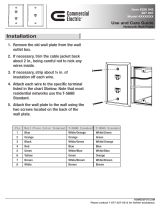
4 Connection
4.1 Connection Box EDC-AKS1, Art. No. 74125
CON4: for one heater and one fan with 24VAC
CON3, CON5, CON6, CON7: to the dome camera
CON2: for external connectiion
CON8: for AC line connection (230VAC)
CAUTION: Power input cable uses suitable product to National Requirement be outdoor.
Minimum conductor size: 0,75mm
2
, 18AWG
NOTE: To male connections on the Connector Strip, press and hold the button and insert the wire in the
hole below the button. After releasing the button, tug gently on the wire to make certain it is
connected. To disconnect a wire, press and hold the button above the wire and pull out the wire.
NOTE: Place the BNC connector at the safe position not to make a short circuit.
Input AC Linenot connected

18
4.1.1 Using the Connection Cable EDC-OPX/IPX-CC1, Art. No. 74143
(Wiring Dome Housing, Box Art. No. 74125)
Where used, the # 74143 connection cable replaces the original conduit gland in the dome housings of the Fastrax III
series.
Cable assignment
Colour Description Colour Description
brown / white
24VAC housing
fan and heater
orange GND
black / white red / white 24VAC+
red COM1 orange / white 24VAC–
brown NC1 yellow / black FGND
black NO1 green / white RX- (TX-)
grey AL1 grey / white RX+ (TX+)
blue AL2 blue / white GND
green AL3
yellow AL4
open ends
(assignment
see table)
Dome Side Housing Side

19
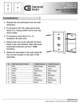
4.2 Power & Connection Box NTDF-AKS1, Art. No. 74145
Input AC Line
CON4: for one heater and one fan with 24VAC
CON3, CON5: to the dome camera
CON2: for external connectiion
CON8: for AC line connection (230VAC)
CAUTION: Power input cable uses suitable product to National Requirement be outdoor.
Minimum conductor size: 0,75mm
2
, 18AWG
NOTE: To male connections on the Connector Strip, press and hold the button and insert the wire in the
hole below the button. After releasing the button, tug gently on the wire to make certain it is
connected. To disconnect a wire, press and hold the button above the wire and pull out the wire.
NOTE: Place the BNC connector at the safe position not to make a short circuit.

20
4.2.1 Using the Connection Cable NTD-OPX/IPX-CC1, Art.-Nr. 74144
(Wiring IP Dome – Box, Art. No. 74145)
Where used, the # 74144 connection cable replaces the original conduit gland in the dome housings of the Fastrax III
series.
Pin assignment
Connector 1: Network Jack RJ45 (RX+, RX-, TX+, TX-)
Connector 2: 12VDC Jack (12VDC+, GND)
Connector 3: Alarm I/O and RS-485 must be assembled to 16pin connector
(RS-485 RX+, RX-485 RX-, ALARM OUT, ALARM IN).
Connector 4: Terminal Block 2 pin (24VAC Fan / Heater: 24VAC+, 24VAC-)
Connector 5: Terminal Block 3 pin (12VDC+, GND)
Cable assignment
open ends
open ends
(assignment
see table)
Colour Description Colour Description
orange RX+
Network
orange / white RS-485 RX+
Telemetry
brown RX– green / white RS-485 RX–
green TX+ yellow / black Alarm output
grey TX– brown / white Alarm output
red / white 12VDC+
red
Alarm input 1
black / white
GND yellow
blue / white 24VAC+
blue
Alarm input 2
grey / white 24VAC–
black
Dome Side Housing Side

21
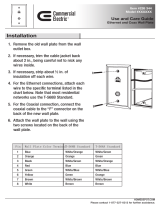
5. Mounting
CAUTION: Refer all servicing to qualified service personnel.
1. Drill 4 holes on the wall to fix the mounting base.
CAUTION: • For safety, the structure wall that this unit is installed on should be strong enough to support
a minimum of 25kg.
• For safety, connect a Ass’y Dome Housing under 9kg to the nut.
2. Insert the plastic anchors inside each hole.
3. Attach the mounting base by using the screws (PTS1 M6) and the plastic anchors on the wall.
4. Fix the BNC cable with the cable clamp within the mounting.
5. Close the mounting and tighten the screws.
NOTE: You can prevent moisture from generating inside as sealing gaps between PGs and cables
completely.
Seal this using the Teflon tape
around a thread of a socket.
Wire colours according to EIA/TIA 568B
Pin Colour Ethernet Connected
1 orange Transmit Data + yes
2 orange / white Transmit Data – yes
3 green Receive Data + yes
4 blue / white not used – –
5 blue not used + –
6 green / white Receive Data – yes
7 brown not used + –
8 brown / white not used – –
Cable assignment (network plug)

22
Mounting accessories
N0. Part Name Description Q’ty
1
Plastic anchor BHS M4, L=8 4
2
Screw PTS1 M6, L=35 4
3
Screw BHS M3, L=8 1
4
Cable clamp 4N, Nylon
1
5
PG gland * 16.0 1
6
L-wrench 4mm 1
7
L-Torx wrench T20, 5mm-Typ
1
8
Screw BHS M4, L=8 1
9
Washer (star) M4 1
* To be removed when using a # 74143/ 74144 connection cable.
NOTE: The range of the operating temperature of this unit is -40°C ~ +50°C. Therefore, don’t expose
this unit directly to the sun and install it at a well ventilated place so that the inside temperature
may not increase more.
6. After assembling the housing to the socket (15), tighten the knocking screw by 4mm L-wrench.

23
6. Specifications
Type EDC-AKS1 NTDF-AKS1
Art. No.
74125 74145
Output voltage 1
24 ~ 28VAC 12VDC
Output voltage 2
– 24VAC
Output current
3A max. (24VAC) 1A (12VDC); 2.2A (24VAC)
Alarm inputs
4 2
Alarm outputs
2 (NO / NC)
1
Cable entries
up to 3x glands PG16
Internal connections
Terminal connectors for: 230VAC, 24VAC,
RS-485, Alarm in/output, etc.
Terminal connectors for: 230VAC, 24VAC,
RS-485, network, Alarm in/output, etc.
Protection rating
IP66
Supply voltage
230VAC / 50Hz
Power consumption
80W
Temperature range
-40°C ~ +50°C
Housing
Aluminium
Colour
Pantone Cool Gray 1C
Dimensions
See drawing
Weight
3.8kg
Parts supplied
Power & connection box, fixing screw and tool set, manual
Accessories
Art. No. Type Description
74143
EDC-OPX/IPX-CC1 Connection cable for EDC-xxx-2 Fastrax III Standard Domes in In/Outdoor housing
(only EDC-AKS1, Art. No. 74125)
74138
EDC-AKS1/MP Adapter plate for fixation of EDC-AKS1 to EDC-PM7 or EDC-CMA2
74055
EDC-PM7 Pole mount adapter for EDC-IPS/OPC housings and wall bracket EDC-WMB1
74054
EDC-CMA2 Corner mount adapter for EDC-IPS/OPC housings and wall bracket EDC-WMB1
Accessory to
Art. No. Type Description
74130
EDC-OPC-2/24V Pendant mount outdoor dome housing, sun shield, clear bubble 6,5”, 24VAC
74134
EDC-IPS-2/24V Pendant mount indoor dome housing, tinted bubble 6,5”, 24VAC
74135
EDC-IPC-2/24V Pendant mount indoor dome housing, clear bubble 6,5”, 24VAC
74136
EDC-OPS-2/24V Pendant mount outdoor dome housing, sun shield, tinted bubble 6,5”, 24VAC
74123
EDCH-142E/C 1/4” Day&Night 22x HighSpeed Dome camera, clear bubble, 24VAC, 480TVL
(only EDC-AKS1, Art. No. 74125)
74119
EDCH-144E/C 1/4”
Day&Night 26x HighSpeed Dome camera housing, clear bubble, 24VAC, 480TVL
(only EDC-AKS1, Art. No. 74125)
7. Dimensional drawing
See page 44

44
7. Maßzeichnungen / Dimensional Drawings / Croquis / Medidas
Maße/Dimensions/Medidas: mm
126
174
145
7.0
154.6
149
6.0
194
150
270
80
NF 1.5”
215
Technische Änderungen vorbehalten
Technical changes reserved
Nous nous réservons toutes modifications techniques.
Sujeto a modificaciones técnicas
© Copyright by VIDEOR E. Hartig GmbH 10/2009
eneo
®
ist eine eingetragene Marke der Videor E. Hartig GmbH
Vertrieb ausschließlich über den Fachhandel.
eneo
®
is a registered trademark of Videor E. Hartig GmbH
Exclusive distribution through specialised trade channels only.
eneo
®
est une marque propriété de Videor E. Hartig GmbH
Distribution et vente à travers les distributeurs spécialisés.
eneo
®
es una marca registrada de Videor E. Hartig GmbH
Venta a traves de los distribuidores especializados.
VIDEOR E. Hartig GmbH
Carl-Zeiss-Straße 8 · 63322 Rödermark/Germany
Tel. +49 (0) 6074 / 888-0 · Fax +49 (0) 6074 / 888-100
www.videor.com
Adapterplatte #74138 für Mastmontage in Verbindung mit Kit #74055
oder Eckmontage mit Kit #74054
Adapter plate #74138 for pole mount in connection with kit #74055
or corner mount kit #74054
Plaque adaptateur #74138 pour montage sur mât en combinaison avec le kit #74055
ou montage en angle avec le kit #74054
Placa de adaptación # 74138 para montaje en mástil junto con kit # 74055
o montaje en esquina con kit # 74054
/