GE AE1RD20DM0V1 Owner's manual
- Category
- Split-system air conditioners
- Type
- Owner's manual
This manual is also suitable for

0
|
0_
0_
0_
0 91wwlmlm
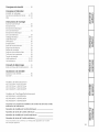
Safety Instructions ............ 2
Operating Instructions
Batteries ............................ 3
Careand Cleaning ............... 6, 7
RemoteControlFeatures ........ 4, 5
Installation Instructions
AirPurgingand LeakageTest..... 15
BeforeYouBegin ................... 8
ConnectionTubing ............... 11
Dimensions ........................ 9
Drainage Hose ................... 11
ElectricalRequirements............. 8
ElectricalWiring .............. 12-14
Indoor Unit .................... 12,1:3
Location .......................... 10
Outdoor Unit .................. 14,15
Tubing Hole....................... 11
PowerLine........................ 14
Mounting Plate ................... 11
TestOperation .................... 16
Wiring Indoor Unit ................ 12
Wiring Outdoor Unit .............. 14
Troubleshooting Tips ........ 17
Normal Operating Sounds........ 17
Consumer Support
ConsumerSupport ...... BackCover
Warrantg ......................... 18
Cool Only Models
AE1CDIOAM / AEOCDIOAM
AE1CD14DM / AEOCD14DM
AE1CD2ODM / AEOCD2ODM
Heat/Cool Models
AE1 RD10AM / AEORD10AM
AE1 RD14DM / AEORD14DM
AE1 RD2ODM / AEORD2ODM
Climatiseurs
inibloc
La section franqaise commence a la page 19
Acondicionadordeaire
desistemaminisplit
La secci6n en espahol empieza en la pdgina 37
Write the model und seriul numbers here
for the indoor und outdoor units:
Indoor Model #
Indoor Seriul #
Outdoor Model #
Outdoor Seriul #
Find these numbers on a label on the side of
eachunit.
49-7600 05-09JR

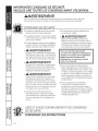
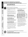
IMPORTANT SAFETY INFORMATION.
READ ALL INSTRUCTIONS BEFORE USING.
tl WARNING!
For your safety, the information in this manual must be followed to minimize the risk of fire, electric
shock or personal injury.
SAFETY PRECAUTIONS
Use this equipment onlg for its intended
purpose as described in this Owner's
Manual.
This sgstem must be properlg installed
in accordance with the Installation
Instructions before it is used.
@All wiring should be rated appropriate for
the current value listed on the rating plate.
Use onlg copper wiring.
,tl, WARNING!Riskofelectric
shock. Can cause injurg or death: Earth
connection is essential before connecting
the power supplg.
,_ WAR N ! N G_ Riskof electric
shock. Can cause injurg or death: Disconnect
all remote electric power supplies before
servicing.
WARN!NG!Riskof electric
shock. Can cause injurg or death: Repair or
replace immediatelg all electrical wiring
that has become fraged or otherwise
damaged. Do not use wiring that shows
cracks or abrasion damage along its
length or at either end.
iiiiiiiiiiii_iiii_
iiiiiiiiiiii_iiii_
All electrical work must be completed bg a
qualified electrician and completed to local
and national building codes and regulations.
Any servicing must be performed by a
qualified individual.
WARNING!Riskof fire. Can
cause injurg or death: Do not store or use
combustible materials, gasoline or other
flammable vapors or liquids in the vicinitg
of this or ang other appliance.
For any service which requires entry
into the refrigerant sealed system,
Federal regulations require the work
be performed by a technician having
a Class II or Universal certification.
iiiiiiiiiiii_iiii_
All air conditioners contain refrigerants,
which under federal law must be removed
prior to product disposal. If gou are getting
rid of an old product with refrigerants, check
with the compang handling disposal.
R/410Aair conditioning sgstems require
contractors and technicians to use tools,
equipment and safetg standards approved
for use with this refrigerant. DO NOT use
equipment certified for R22 refrigerant onlg.
READAND FOLLOW THISSAFETY INFORMATION
CAREFULLY.
SAVE THESE INSTRUCTIONS

Operating the air conditioner. GEAppliances.com
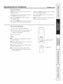
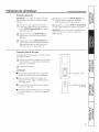
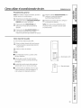
General Procedure
NOTE:Forbest results,point the remote control
at the indoor unit.
r-_ Hake surepower isconnected and pressthe
ON/OFFpad to start the sgstem.
F2-] Pressthe NODE pad to selectthe desired
operation mode.
r-_ Pressthe SWINGpad for automatic rotation of
the louvers.Pressagain to stop the rotation.
[_] Pressthe FAN pad to setthe desiredfan speed
(AUTO/Low/Medium/High).
[_ Pressthe TENP+/- pads to set the desired
temperature.
NOTE:Fordetailed remote control instructions, see
About the remote control section.
How to Insert Batteries
Theremote control usestwo AM batteries.
r-_ Removethe cover from the back of the remote
control and insert two new batteries (pag
attention to the polaritg).
F2-] Reattach the cover.
NOTES:
m Do not mix new and usedbatteries or different
tgpes of batteries.
[] Removebatterieswhen the remote control isnot
in usefor an extended time.
[] The remote control signal can onlg be received
within a range of 20ft.
[] The remote control should be placed about
] feet or more awag from TVsetsor ang other
electrical appliances.
Batterytype:AAA
-- Batterycover
]

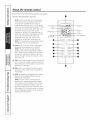
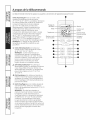
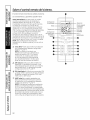
About the remote control.
Theremotecontrol transmitsthesignalsto thesystem.
Featuresand appearancemay vary.
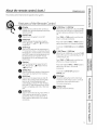
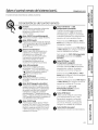
AUTO--In this mode, the unit automatica%
controls the room temperature within the
range of 77°F and 68°F.The fan will run
continuously while the unit is in AUTOmode.
When the room temperature exceeds 77°F,the
unit will go into COOLMode. When the room
temperature drops to 73°F,the fan will
continue to run but COOLMode will turn off.
When the temperature drops below 68°F,the
unit will go into HEATMode. When the
temperature reaches 73°F,the fan will
continue to run but HEATMode turns off.
NOTE:This temperature range setting cannot
be adjusted and will not be displaged.
¢_ COOL--Use to cool the room to the desired
temperature set between 61°F and 86°F.
NOTE:The unit will not provide optimum
cooling if the outside temperature is below
60°F. Under certain conditions, the unit mag
activate the antifreeze protection cgcle for
approximatelg 5 minutes to remove ice from
the indoor coil.
666DRY--Use to dehumidifg the room. The fan will
run at a fixed low speed to provide maximum
dehumidification. The temperature can be set
between 61°F and 86°F.
_€ FAN--Use to turn ON and OFFthe fan-onlg
operation. COOL,HEATor DRYmode will not
be provided.
_X HEAT (on models so equipped)--Use to warm
the room to the desired temperature set
between 61°F and 86°F.
NOTE:The unit will not provide optimum
heating if the outside temperature is below
14°F.Under certain conditions, the unit mag
activate the antifreeze protection cgcle for
approximatelg 8 minutes to remove ice from
the outdoor coil. During this cgcle, it is normal
to hear operating sounds such as refrigerant
flowing inside the sgstem.
e
o
o
______@
@
-- Operation
-- Sleep on
gon
-- Clock andtimer

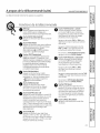
About the remote control. contJ
The remote control transmits the signals to the system.
GEAppliances.com
Features of the Remote Control
O isplag 0
Displagsall set contents when turned on.
Displagsonlg the set temperature and time
when turned off.
O
0
0
ON/OFF Pad
Pressto turn the sgstem on and off.
MODE Pad
Pressto change the operation mode to
AUTO,_ (COOL),666(DRY),dSf_(FANONLY)
or _:_(HEAT).
TEMP Pads
Press+to increasethe set temperature in
!°F increments. Press- to decrease the set
temperature in !°F increments.Inthe COOL
and HEATmodes,the settemperature can
be selected from 6!°F to 86°RTheset
temperature will not be displaged in the
AUTOmode.
FAN Pad
Pressto change the fan speedto AUTO
FAN,-,,(LowFan),..,J (Medium Fan)or
_-,IJ (HighFan).
SWING Pad
Pressfor automatic rotation of the louvers.
Pressagain to stop them from rotating.
SLEEPPad
Pressto turn the sleepmode on and off.
When in the cooling mode and the sleep
timer isset,the set temperature will
automaticallg increase 2°Fafter the first
hour and 2°Fafter the second hour.SLEEP
Mode iscompatible with COOL,HEATand
DRY.
CLOCK Pad
Pressto set the time of dag. PressTIME-or
TIME+padsto set the time in 1-minute
increments.Pressand hold the TIME-or
TIME+padsto set the time in !0-minute
increments.
O
0
0
T-ON (Timer © ON) Pad
When the air conditioner is off,pressT-ON
(timer on)to set it to turn on automaticallg
(usingits previoussettings)at the time gou
set.
PressTIME- or TIME+pads to set the start
time in 1-minute increments.
Pressand hold the TIME-or TIME+ padsto
set the start time in !0-minute increments.
TocancelQ ON (T-ON),pressthe CANCEL
pad.
T-OFF (Timer © OFF)Pad
When the air conditioner ison,pressT-OFF
(timer off)to set itto automatically turn off
at the time you set.
PressTIME- or TIME+pads to set the turn-
off time in 1-minute increments.
Pressand hold the TIME-or TIME+ padsto
set the turn-off time in !0-minute
increments.
Tocancel © OFF(T-OFF),pressthe
CANCELpad.
TIME Pads
Usewhen setting the CLOCKand timers
(T-ONand T-OFF).Pressto set in 1-minute
increments. Pressand hold to set in
!0-minute increments.
CANCEL Pad
Pressto cancel the timer(s).

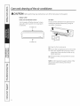
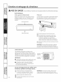
Careand cleaning of the air conditioner.
Indoor Unit
Grille, Case and Remote Control
Turn the sgstem off beforecleaning. Toclean,
wipe with a soft, drg cloth. Donot usebleach
or abrasives.
Air intakevent
Airoutletvent
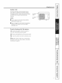
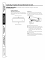
Air Filters
Thetwo air filters behind the front grilleshould be
checked and cleaned at least everg 30 dags or
more often, ifnecessarg.
r_ open the front access panel.
F2-] Pullthe filter tab slightlg forward to remove the
filter.Cleanthe filter with a vacuum or warm,
soapgwater. Rinseand allow the filter to drg
before replacing it.
r_ Reinsertthe filters and closethe front access
panel.
NOTE:DONOToperate the sgstem without a filter
becausedirt and lint will clog it and reduce
performance.

Outdoor Unit
The heat exchanger coils and panel vents of
the outdoor unit should be checked regularlg.
If clogged with dirt or debris, the heat exchanger
and panel vents should be professionallg
cleaned.
NOTES:
mPower supplgmust be disconnectedbefore
cleaningthe outdoor unit.
mOirt_lor cloggedcoils wi!!reducethe operating
e_ciency ofthe sgstem and cause higher
operating costs.
Airintake
vents
Airoutlet
vent
GEAppliances.com
If you're closing up for the season...
IT] Operate the sgstem in the fan mode for 2
hours. This will drg out the sgstem.
[_ Remove the batteries from the remote control.
[_ Cover the outdoor unit with a protective cover.
NOTE: Next season make sure to remove the
protective cover from the outdoor unit before
restarting the sgstem.

I
I
stall tio
structio
Mi
Air
i Split-Sg
Co diti
te
e
BEFORE YOU BEGIN
Readthese instructions completely and
carefuIIg.
• IMPORTANT - savethese instructions for local
inspector's use.
• IMPORTANT - Observeallgoverningcodes
and ordinances.
• Note to Installer - Besure to leave these instructions
with the Consumer.
• Note to Consumer - Keep these instructions for future
reference.
• Skill level - A licensed, certified (to handle refrigerant-
R410A,recovery, etc.)technician and a qualified
electrician ore required for installation of this split
air conditioning system.
• Completion time - Approximately 2V2hours
• Two people are required to install this unit due to
the weight of the product.
• Proper installation isthe responsibility of the installer.
• Product failure due to improper installation is not
covered under the Warranty.
• For personal safety, this system must be properly
grounded.
• Protective devices (fuses or circuit breakers)
acceptable for installation ore specified on the
nameplate of each unit.
• Servicing and installation of the refrigerant system
must be performed only by a licensed, HVAC-certified
technician.
• Make sure to avoid wiring or plumbing inside the wall
when installing.
• Forany service which requires entry into the refrigerant
sealed system, Federal regulations require the work be
performed by o technician having o Class IIor Universal
certification.
ELECTRICAL REQUIREMENTS
• Becertain all wiring complieswith local building codes and
NECand that the supply voltage for this system iscorrect.
Thesystem supply voltage isconnected to the outdoor
unit only.
• Checkthe rating nameplate on the sidepanel of outdoor
unit for requiredcircuit protection rating and required supply
voltage.
UseUL-opprovedelectrical branch circuit disconnect
for providing supply voltage to split system indoor and
outdoor units.Locate disconnect within sight and readily
accessibleper NECand localcodes.
Allwiring shouldbe rated appropriate for the current value
listed on the rating plate.
• Becertain there isan uninterrupted, unbroken electrical
ground connection.
• Wiring should be encased in liquid-tight tubing with
connections sealedwith liquid-tight connectors.
-&CAUTION:
• Do not use on extension cord with this system.
• Aluminum building wiring mag present special
problems-consult a qualified electrician.
• When the unit is in the STOPposition, there is still
voltage to the electrical controls.
• Disconnect the power to the system before
servicing bg removing the branch circuit fuses
or turning the circuit breakers off at the panel.
• DO NOT use equipment certified for R22refrigerant
only.

Installation Instructions
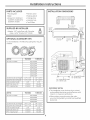
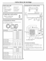
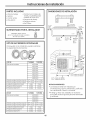
PARTS INCLUDED
• Mounting plate
• Sealer
• Screws(5for 10,000and
la,000 BTUmodels/10 for
20,000 BTUmodels)
• Remotecontrol
• BatteriesAAA(2)
• Drainagehose
• Insulationhose
• Two (2)filters
SUPPLIED BY INSTALLER
Adapter: 1/4" male flare with Schrader
valve x 5/16" female (1/2"-20UN)
OPTIONAL ACCESSORY KITS
To aid installation, the following tubing kits may be
ordered:
GE Kit TUE1650 TUE3250
Foruseon models AE1CD!0AM
AEOCD!0AM
AE1RD10AM
AEORD10AM
AE1CD!4DM
AEOCD14DM
AEIRD14DM
AEORD14DM
1/2" x 16 ft.
1/4" x 16 ft.
16 ft.
included
included
Suction line dia. and length 1/2" x 32 ft.
Liquid line dia. and length 1/4" x 32 ft.
Tube insulation length 32 ft.
Wall hole sleeves (2) included
PVCwrapping tape included
GE Kit
For use on models
TUE1662 TUE3262
AE1CD20DM
AEOCD20DM
AEIRD20DM
AEORD20DM
Suction line dia. and length 5/8" x 16ft. 5/8" x 32 ft.
Liquid line dia. and length 3/8" x 16ft. 3/8" x 32 ft.
Tube insulation length 16 ft. 32 ft.
Wall hole sleeves (2) included included
PVCwrapping tape included included
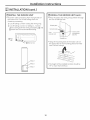
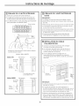
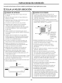
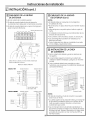
INSTALLATION DIMENSIONS
_6" ormorespace
6" or more _ tothe ceiling 6" or more
spaceto f'//' ......................_................... spaceto
thewall f/ " ' "_ tf?e_all
,
118"ormore_ 79"ormore_ // VVrappiFg
airoutletside, hspacetothe --I- TublnoTuhin_holehnb,tapep
T_oor T sleeve
:"20"ormorespace
Ltothecover
12"ormore
spacetothe
wall
79"or moreair
outlet side
21¼"-10Kand14KBTUmodels
22_?'-20KBTUmodels
11¼"-10Kand14KBTUmodels
11_"-20KBTUmodels
IMPORTANT NOTES:
,,The installation must be done bg a trained
and qualified electrician and technician with
Class II or Universal certification.
,,When picking up and moving the units,
you must be guided bg trained and qualified
personnel.

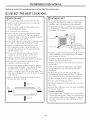
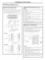
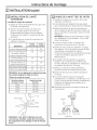
Installation Instructions
Read these instructions completely and carefully; then follow step by step.
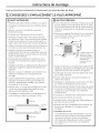
SELECT THE BEST LOCATION
r_ INDOOR UNIT
• Do not allow ang heat or steam near the unit.
• Select a location where there are no obstacles
in front of the unit.
• Make sure that condensate drainage can be
convenientlg routed awag.
• Do not install near a doorwag.
• Ensure that the space around the left and right
of the unit is more than 6". The unit should be
installed as high on the wall as possible, allowing
a minimum of 6" from ceiling.
• Use a stud finder to locate studs for mounting and
to prevent unnecessarg damage to the wall.
• Install on studs and in a location from which
the condensation water can be drained out
convenientlg and that permits easg connection
with the outdoor unit.
• Do not cover the inlet and outlet so that the
outflow air can reach all parts of the room.
• Install in a location that is strong enough to
withstand the full weight and vibration of the unit.
• Be sure that the installation conforms to the
installation dimension diagram.
• Leave enough space to allow access for routine
maintenance. The height of the installed location
should be 79" or more awag from the floor.
• Install in a location that is 3 ft. or more awag from
other electrical appliances, such as televisions and
audio devices.
• Select a location that gives gou easg access to
remove and clean the filter.
Morethan6"
More f, _ , , .... More
Morethan79"
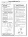
[]OUTDOOR UNIT
• If an awning is built over the unit to prevent direct
sunlight or rain exposure, make sure that heat
radiation from the condenser is not restricted.
• Ensure that the space around the back and sides
is more than 12". The front of the unit should have
more than 79" of space.
H
Morethan12"
Theplatformmust
supporta minimumof
Morethan79" 200Ibs.SeeInstallation
Dimensionsformounting
holespacing.
• Install in a location that is strong enough to permit
safe installation and to withstand the full weight
and vibration of the unit.
• Construct and anchor o strong and level mounting
base or pod for the outdoor unit.
• Anchor the outdoor unit through its four mounts,
using bolts.
• Select o location from which noise and outflow
air emitted bg the unit will not inconvenience
neighbors.
• In humid locations, the unit mog sweat and
condensation (water) mag drip from it. Take this
into consideration when choosing the location.
• Select a location that has sufficient ventilation.
• Do not cover the inlet and outlet.
• Install unit owog from flammable gas or corrosive
gas leaks.
• Be sure the installation conforms to the installation
dimension diagram.
• Rooftop Installations:
If the outdoor unit is installed on a roof structure,
be sure to level the unit. Ensure the roof structure
and anchoring method are adequate for the unit
location. Consult local codes regarding rooftop
mounting.
10

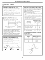
Installation Instructions
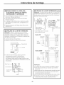
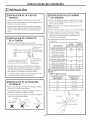
INSTALLATION
[] INSTALL THE MOUNTING PLATE
• Always mount the mounting plate horizontally.
• Attach the mounting plate at the selected location
with screws supplied with the unit.
• Be sure that the mounting plate has been
attached firmly enough to withstand the weight
of on adult of 130 Ibs. Also, the weight should be
evenly shored by each screw.
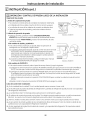
171INSTALL THE TUBING HOLE
• Make the tubing hole in the wall at o slight
downward slant to the outdoor side.
3"fromright
edgetocenterof
righttubinghole
f
\
Holeis2"diameterfor1OKand14KBTU l_A''frombottom
modelsand2_''diameterfor edgetocenterof
20KBTUmodels, righttubinghole
• To let water drain and prevent damage to wiring
and tubing, insert o 2V/' plastic pipe, cut to o
length equal to the wall depth. Insert the tubing
and wiring through the pipe.
• Copper tubing should be copped until ready to
install flare fitting, to prevent contamination.
[_] INSTALL THE DRAINAGE HOSE
• For good drainage, the drain hose should be
placed at o downward slant.
• Do not wrench or bend the drain hose or allow
it to contact standing water.
• The extended drainage tube in the room should
be wrapped with the insulating materials.
\
X X Flooded
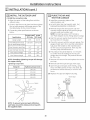
I_ INSTALL THE CONNECTION TUBING
• Connect the copper tubing with the relevant union
tubes of the indoor unit and tighten the flare nut
of the connection tubes.
NOTE: Be careful when bending the connection
tubes to ovoid damaging them.
1. Align the center of the tube flere with the relevant
velve.
2. Screw in the flare nut by hand end then tighten
the nut with spanner and torque wrench. See the
table below for the correct torque.
3. Connecting tube specifications ere shown below:
10,000/14,00020,000
Specifications BTU Units BTU Units
DesignLength 20 ft. 26.2ft.
Extra RefrigerantCharge 0.16oz./ft. 0.54oz./ft.
PerFt.AboveDesignLength
Outer Diameter Liquid Pipe 1/4" 3/8"
Outer Diameter GasPipe 1/2" 5/8"
Max.Distance Height 33 ft. 33ft.
Max.Distance Length 68 ft. 98 ft.
NOTE: Exceeding tightening torque will damage
the copper tubing.
Tightening torque table
Tubing OD
1/4"
3/8"
1/2"
5/8"
Tightening torque(in./Ib.)
140-170
270-310
440-480
530-570
Flarenut
Joint
Spanner
uewrench
11

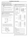
Installation Instructions
INSTALLATION (cont.}
[_] CONNECT ELECTRICAL WIRING
BETWEEN INDOOR AND OUTDOOR
UNITS
• All wiring should be rated appropriately for the
current value listed on the rating plate.
• The power supply should accommodate the rated
voltage.
• Wiring must be done by a qualified electrician
according to local codes, regulations and this
manual.
• All wiring connections should be tightened securely.
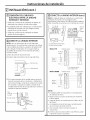
[61WIRE THE INDOOR UNIT
NOTE: Use UL-approved electrical branch circuit
disconnect for providing supply voltage to split system
indoor and outdoor units. Locate disconnect within sight
ond readilg occessible per NECand local codes.
1. Open the front access panel.
2. Remove the cover plate of the electrical box.
\
:::::::':_ Accesspanel
i -- Coverplate
J o
3. On the back of the indoor unit, remove the
conduit connecting cover. Using the fixing nut,
connect the conduit to the connecting cover.
Route the wire leads through the unit to the
electrical box area. Reinstall the connecting cover.
Backof unit IIII
Fixingnut /1/
Connecting cover
Conduit
12
F6]WIRE THE INDOOR UNIT {cont.}
NOTE: Wiring must be done by a qualified electrician
according to the local codes and regulations and
this manual. The connecting wire should be correctly
connected to the circuit interface.
Electricalwiresmustbesecured
with attachedstrainreliefs.
_w -way
terminal
board
er
j onnection
cord
115VModels Outdoorunit Indoorunit
Tobranch
circuit
Powersupply _
:tI:i!
roun
3.
o
_3J
B_
%1will beusedfor neutral
in 115Vmodels.
230/208V Models
Outdoorunit
Tobranch
circuit
Powersupply _1
Indoorunit
NOTES:
• Wiring should be consistent with the wiring
diagrams above.
• Tighten the nut of the terminal board to keep
the board secured.
• After tightening, the wire cannot be removed
if pulled.
• Incorrect wiring will cause the air conditioner
to work abnormally.
• Incorrect grounding will cause a short circuit.
4. Replace the cover plate over the electrical box
and lower the access panel into position.

Installation Instructions
INSTALLATION (cont.}
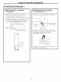
[71INSTALL THE INDOOR UNIT
• Route the tubes and wiring from the right side of
the indoor unit. Cut off the railings from the
chassis as necessary.
1. Cut off tailings 1 when routing the wiring only.
2. Cut off railings 1 and 2 (or railings 1, 2 and 3)
when routing both the wiring and tubing. (_ and
(_ below are the recommended tubing.
C) Right
tube
jTailings 3
I Jl jTailings 2
I_[_ i-- Tailings1
[2] INSTALL THE INDOOR UNIT (cont.}
• Wrap the tubes and wiring and pull them through
the cut-off-tailings hole.
Wrappingtape
Connectiontubes
Power Controlcord(for
connectioncord cooling/heating
typeonly)
Drainagehose
• Hang the mounting slots of the indoor unit on
the upper tabs of the mounting plate and make
sure it is firm enough.
• The height of the installed location should be
79" or more from the floor.
13

Installation Instructions
INSTALLATION (cont.}
[_]WIRE THE OUTDOOR UNIT
1. Open the cover of the outdoor unit.
2. The connecting wire lead from the terminal board
of the indoor unit must be connected correctly.
3. The connecting wire should be a little longer so
that it can be maintained easily.
6-wayterminalboard
\
,x
\\
O
©
Wrapelectricalcordswith attached
metaltietoprovidestrainrelief.
10,000and14,000BTUModels
115VModels Outdoorunit Indoorunit
Tobranch
circuit
Powersupply _]
roun
%1will beusedfor neutral
in 115Vmodels.
230/208VModels Outdoorunit
Powersupply _
T° r nchl
circuit
Ground_ I
Indoorunit
FsqWIRE THE OUTDOOR UNIT (cont.}
NOTES:
• Wiring should be consistent with the above wiring
diagrams.
• Wiring must be correct.
• Tighten the nut of the terminal board to keep the
board secured.
• After tightening, the wire cannot be removed if
pulled.
• Incorrect wiring will cause the air conditioner to
work abnormally.
• Incorrect grounding will cause a short circuit.
• Electrical connections must be made by a qualified
electrician.
• All electrical work must be completed according to
local codes and regulations.
[] INSTALL THE POWER LINE
1. Open the wiring cover and remove the knockouts.
2. The connector should be secured by the nut, and
the wiring cover should be replaced and secured
with the included screw.
3. All wiring should be protected by liquid-tight
tubing, and connections to the wiring cover
should be with liquid-tight connectors.
14
Electricalbox
assembly
Wiringcover
Connector
NOTES:
• The connecting wire and connection tube cannot
touch each other.
• The top cover of the outdoor unit and the electrical
box assembly should be fixed by the screw.
Otherwise, it can cause a fire or a short circuit
caused by water or dust.
• Use a UL-approved electrical branch circuit
disconnect for providing supply voltage to the split
system outdoor unit. Locate the disconnect within
sight and readily accessible per NEC and local
codes.

Installation Instructions
INSTALLATION (cont.}
| INSTALL THE OUTDOOR UNIT
• Install the connection tube
i. Align the center of the tubing flare with the
relevant valve.
2. Screw in the flare nut by hand and then tighten
the nut with spanner and torque wrench. See
the table below for the correct torque.
3. Connecting tube specifications are shown
below:
10,000/14,00020,000
Spedficetions BTU Units BTU Units
Design Length 20ft. 26.2ft.
ExtraRefrigerantCharge 0.16oz./ft. 0.54oz./ft.
PerFt.AboveDesignLength
Outer Diameter Liquid Pipe 1/4" 3/8"
Outer Diameter GasPipe 1/2" 5/8"
Max.Distance Height 33 ft. 33ft.
Max.Distance Length 68 ft. 98 ft.
NOTE: Exceeding tightening torque will damage
the copper tubing.
Tightening torque table
Tubing OD
1/4"
3/8"
1/2"
5/8"
Tighteningtorque(in./Ib.)
140-170
270-310
440-480
530-570
Flarenut
Joint
Spanner
uewrench
NOTE: To prevent wind and pest infiltration,
seal holes around the tubing and wiring with
the supplied sealer.
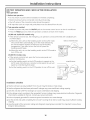
I-_ PURGE THE AIR AND
TEST FOR LEAKAGE
,
2.
3.
,
5.
Install the connecting tubes of the
indoor/outdoor unit.
DO NOT OPEN THE GAS VALVES UNTIL THE
EVACUATION PROCESSIS COMPLETE.
Remove the gas line service port cap and
connect the gas valves of the vacuum gauge,
vacuum pump and outdoor unit.
NOTE: Connect bg using a 1/4" Female x
1/2" Male Adapter Access Fitting (obtain Iocallg).
Start the vacuum pump. (Running time should
be more than 15 minutes.)
Check the vacuum with the vacuum gauge. The
gauge should read -30 in. Hg. After evacuation,
fulls close the handle on the manifold valve
(on the vacuum pump device). Then stop the
vacuum pump and disconnect it.
6. The pressure should be kept for 1-2 minutes
to confirm that the reading of the vacuum
gauge does not change. The pressure should
be-30 in. Hg.
7. Remove the vacuum line and replace the service
port cap.
8. Remove both the liquid and gas valve caps.
9. Open the gas and liquid valve entirelg, using
the 5 mm Allen wrench. If this is not done, the
performance will be reduced, or an error will
OCCUr.
i0. Replace the caps and tighten securelg.
(
Cap
Liquid_hp_
Gastube
Vacuumgauge
Vacuumpump
15

Installation Instructions
_-_ TEST OPERATION AND CHECK AFTER INSTALLATION
Test operation
1. Before test operation
• Do not switch on power before installation is finished completely.
• Electrical wiring must be connected correctly and securely.
• Shut-off valves of the connection tubes should be opened.
• All impurities such us scraps and particulates must be cleared from the unit.
2. Test operation method
• Switch on power and press the ON/OFF pod on the remote control to turn on the air conditioner.
• Press the MODE pad and check the operation conditions of each of the modes.
i0,000 and 14,000 BTU models onlg:
• If the remote control is lost, the emergency run operation can be performed with a ballpoint pen
or similar object.
a. When the unit is off, set the handling switch to the AUTO mode.
The unit will then automatically run in the mode selected by
the microcomputer system according to the surrounding
temperature. If you want to turn the unit off, press the
handling switch again.
b. When the unit is on, set the handling switch to the STOP mode to q
turn off the unit.
20,000 BTU models only:
• If the remote control is lost, open the front access panel and
perform the following:
a. Set the handling switch to the AUTO position to operate in the
AUTO mode. Once there is a remote control signal, the unit will
again be controlled by that signal.
b. Set the handling switch to the STOPposition to turn off the unit.
10,000and14,000BTUModels
20,000BTUModels
Handling
switch
switch
Installation Checklist
Has the unit been securely installed? If not, the unit may full, shake or make noises.
Has the refrigerant leak test been performed? Leakage may cause insufficient cooling capacity.
Does the unit drain well? Poor drainage con cause condensation and dripping.
Is the voltage correct according to the nameplate? Incorrect voltage may cause electrical malfunction. Diagnostic
information is available for this unit. Contact your service technician.
Is the unit properly grounded? A nonsecure ground connection can cause damage.
Are the air inlet and outlet completely free of cover? Covering the air inlet or outlet may cause insufficient cooling
capacity.
Have the length of the connection tubing and refrigerant capacity been recorded? It is important to know these
things for future reference.
16

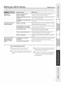
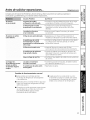
Before gou call for service... GEAppliances.com
Troubleshooting Tips:Save time and moneg! Review the chart below first and gou mag not need to call for service.
Possible Causes What To Do
The sgstem
does not start
The fuse is blown/circuit • Check the house fuse/circuit breaker box and
breaker is tripped, replace the fuse or reset the breaker.
The Timer operation is not set • Check the Timer functions and make sure they are
correctly, set to the desired settings.
The unit does not operate when .This is normal. Wait about ] minutes and the unit
restarted, will restart.
The sgstem does not Airflow is restricted. • Make sure there are no curtains, blinds or furniture
cool as it should blocking the front of the system.
The temperature control mag • Turn to a lower or higher setting. The lowest setting
not be set high or low enough, provides maximum cooling.
The air filter is dirty. • Clean the filter at least every ]0 days.
See the Operating Instructions section.
The room mag have been hot. .When the system is first turned on, you need
to allow time for the room to cool down.
Cold air is escaping. • Check for open furnace floor registers and cold air
returns.
The remote control The batteries are inserted • Check the position of the batteries. They should be
displag is faint or incorrectlg, inserted in the opposite (+)and (-) direction.
shows no displag
at all The batteries mag be dead. - Replace the batteries.
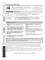
Normal Operating Sounds
m These sounds are common during the
antifreeze cooling or heating modes.
m You may hear a sound like water flowing. This
isthe sound of refrigerant flowing inside the
system.
m A noise that sounds like air being released is a
design feature of dehumidifying water being
processed inside the system.
m You may hear a clicking noise when you start
or stop the unit. This sound isthe expansion
or contraction of the unit due to changes in
the temperature.
17

Split Sgstem Warrantg.
All warrantg service provided bg our designated service network.
Toschedule service,call 866.404.5245. For service in Canada, contact
Gordon Williams Corp. at 1.888.209.0999. Pleasehave serial number
and model number available when calling for service.
Staple Four receipt here.
Proof of the origina! purchase
date is needed to obtain service
under the warrant F.
6E Will Replace:
Any part of the air conditioner which fails dueto a defect in materials or workmanship.
Duringthis limited one-year warranty, GEwill also provide,free of charge, all labor
and related serviceto replacethe defective part.
One Year
Fromthe dateof the
origina!purchase
Five Years
Fromthe dateof the
original purchase
Any part of the sealed refrigerating system (thecompressor,condenser,evaporator
and all connecting tubing) which fails due to a defect inmaterials or workmanship.
Duringthis four-year limited additional warranty, GEwill also provide,free of charge,
all labor and related serviceto replace the defective part.
Service trips to gout home to teach you how to use
the product.
Improper installation, delivers or maintenance. If Sou
have an installation problem, or if the air conditioner is
of improper cooling capacity for the intended use,
contact your dealer or installer. You are responsible for
providing adequate electrical connecting facilities.
Failure of the product resulting from modifications to
the product or due to unreasonable use including
failure to provide reasonable and necessary
maintenance.
In commercial locations labor necessary to move the
unit to a location where it is accessible for service by
an individual technician.
Replacement of house fuses or resetting of circuit
breakers.
Failure due to corrosion on models not corrosion-
protected.
Damage to the product caused by improper power
supply voltage, accident, fire, floods or acts of God.
Incidental or consequential damage caused by possible
defects with this air conditioner.
Damage caused after delivery.
Product not accessible to provide required service.
i XCLUSION OF IMPLIED WARRANTIES--Your sole and exclusive remedy is product repair as provided in this Limited
Warranty. Any implied warranties, including the implied warranties of merchantability or fitness for u particular
purpose, are limited to one year or the shortest period allowed bg law.
This warrant_l is extended to the original purchaser and an_l succeeding owner for products purchased
for home use within the USA and Canada. If the product is located in an area where service b!da GE
Authorized Servicer is not available, Sou may be responsible for a trip charge or Sou ma_l be required
to bring the product to an Authorized GE Service location for service. In Alaska, the warrantbt excludes
the cost of shipping or service calls to sour home.
Some states do not allow the exclusion or limitation of incidental or consequential damages. This warrants
gives Sou specific legal rights, and Sou ma!d also have other rights which vary from state to state. To know
what Four legal rights are, consult btour local or state consumer affairs office or btour state's Attomebt
General.
Warrantor: General Electric Company. Louisville, KV 40225
18
Page is loading ...
Page is loading ...
Page is loading ...
Page is loading ...
Page is loading ...
Page is loading ...
Page is loading ...
Page is loading ...
Page is loading ...
Page is loading ...
Page is loading ...
Page is loading ...
Page is loading ...
Page is loading ...
Page is loading ...
Page is loading ...
Page is loading ...
Page is loading ...
Page is loading ...
Page is loading ...
Page is loading ...
Page is loading ...
Page is loading ...
Page is loading ...
Page is loading ...
Page is loading ...
Page is loading ...
Page is loading ...
Page is loading ...
Page is loading ...
Page is loading ...
Page is loading ...
Page is loading ...
Page is loading ...
Page is loading ...
Page is loading ...
Page is loading ...

Consumer Support.
GEAppliances Website GEAppliances.com
Havea question or need assistancewith your appliance?Try the GEAppliances Website 24 hours a day,
any day ofthe year! Forgreater convenience and faster service,you can now download Owner's Manuals,
order parts or even scheduleservice on-line.
Schedule Service GEAppliances.com
ExpertGErepair serviceisonly one step away from your door.Geton-line and schedule your serviceat
your convenience any day of the year! Or call 800.GE.CARES(800.432.2737)during normal businesshours.
RealLife Design Studio GEAppliances.com
GEsupports the UniversalDesignconcept-products, services and environments that can be usedby
people of all ages, sizesand capabilities.We recognizethe need to design for a wide range of physical and
mental abilities and impairments. Fordetails of GE'sUniversalDesignapplications, including kitchen designideas
for people with disabilities,check out our Website today. Forthe hearing impaired, pleasecall 800.TDD.GEAC
(800.833.4322).
Parts and Accessories
GEAppliances.com
Individualsqualified to servicetheir own appliances can have parts or accessoriessent directly to their homes
(VISA,MasterCordand Discovercards ore accepted).Orderon-line today, 24 hours every day or by phone at
800.626.2002during normal businesshours.
Instructions contained in this manual coverprocedures to be performed by any user. Other servicing
generally should be referred to qualified service personnel. Caution must be exercised,since improper
servicing may causeunsafe operation.
Contact Us
GEAppliances.com
Ifyou are not satisfiedwith the service you receivefrom GE,contact uson our Website with all the details
including your phone number,or write to: General Manager,Customer Relations
GEAppliances,Appliance Park
Louisville,KY/40225
l Register YourAppliance GEAppliances.com
Register your new appliance on-line--at your convenience! Timely product registration will allow for
enhanced communication and prompt serviceunder the terms of your warranty, should the need arise.
Youmay alsomail in the pre-printed registration card included inthe packing material.
Printed in China
-
 1
1
-
 2
2
-
 3
3
-
 4
4
-
 5
5
-
 6
6
-
 7
7
-
 8
8
-
 9
9
-
 10
10
-
 11
11
-
 12
12
-
 13
13
-
 14
14
-
 15
15
-
 16
16
-
 17
17
-
 18
18
-
 19
19
-
 20
20
-
 21
21
-
 22
22
-
 23
23
-
 24
24
-
 25
25
-
 26
26
-
 27
27
-
 28
28
-
 29
29
-
 30
30
-
 31
31
-
 32
32
-
 33
33
-
 34
34
-
 35
35
-
 36
36
-
 37
37
-
 38
38
-
 39
39
-
 40
40
-
 41
41
-
 42
42
-
 43
43
-
 44
44
-
 45
45
-
 46
46
-
 47
47
-
 48
48
-
 49
49
-
 50
50
-
 51
51
-
 52
52
-
 53
53
-
 54
54
-
 55
55
-
 56
56


GE AE1RD20DM0V1 Owner's manual
- Category
- Split-system air conditioners
- Type
- Owner's manual
- This manual is also suitable for
Ask a question and I''ll find the answer in the document
Finding information in a document is now easier with AI
in other languages
Related papers
-
GE AE1CD20DM User manual
-
-
-
-
-
-
GE ZGG300NBP1SS Owner's manual
-
-
-
GE PVB98ST2SS Installation guide
Other documents
-
Woods 59020WD Operating instructions
-
Hoover S5626 Installation guide
-
 GE Monogram Refrigerator refrigerator User manual
-
 Acoustic Energy AE1 Active User manual
-
 Acoustic Energy AE1 Classics Owner's manual
-
Frigidaire FRA062AT72 Owner's manual
-
 Acoustic Energy AE1 Classic LE User manual
-
Hotpoint HTDX100GM0WW Installation guide
-
Black & Decker BPC14CJ Owner's manual
-
Franklin Chef FBC20 Owner's manual


