Shure MICROPHONE WL93 User manual

Category
Microphones
Type
User manual

This manual is also suitable for

GENERAL
Shure Model WL93 and SM93 Microphones are omnidirec-
tional, subminiature, lavalier electret condenser micro-
phones. Their visually unobtrusive design and tailored fre-
quency response make them ideal for body-worn
applications in TV broadcasting, theater, and sound rein-
forcement. Both the Model WL93 and the SM93 feature a
small microphone element that provides full, clear sound
comparable to that of much larger microphones.
The WL93, intended for wireless use, connects directly to a
Shure wireless body-pack transmitter. The SM93, intended for
wired applications, includes a preamplifier assembly for con-
nection to three-pin professional (XLR) audio connectors.
The SM93 requires phantom power, and operates over a
range of 11 to 52 Vdc, covering both DIN and IEC phantom
power standards.
FEATURES
Subminiature lavalier design; ideal size for theater, televi-
sion broadcasting, video, film, and sound reinforcement
Small, inconspicuous mounting hardware
Full, clear sound comparable to larger microphones
Smooth extended frequency response with presence rise
specially tailored for chest-worn microphone operation
Controlled low-frequency rolloff reduces low-frequency
clothing and room noise
Low distortion, wide dynamic range
Uniform omnidirectional polar pattern
Preamplifier assembly (SM93) can be pocketed, strapped
to the body, or clipped to belt or waistband
Wide-range phantom powering (SM93) accepts all com-
monly used voltages
VARIATIONS
Version Cable Color
WL93
1 2 m (4 ft )
Black matte microphone and
SM93
1
.
2
m
(
4
f
t.
)
Black matte microphone and
cable with black accessories
WL93–6 1.8 m (6 ft.)
ca
bl
e
w
ith bl
ac
k
accessor
i
es
WL93T 1.2m (4 ft.) Tan matte microphone and
WL93–6T 1.8 m (6 ft.)
p
cable with tan accessories
CONNECTIONS
Connect the male, four-pin miniature connector (TA4M) at
the end of the 93 microphone cable to the supplied preamplifi-
er (SM93) or to a Shure wireless body–pack (WL93).
NOTE: Do not connect the 93 microphone directly to a
mixer without using the supplied preamplifier or body-pack.
MOUNTING THE MICROPHONE
The tie clips and mounting bracket provided with the WL93
and SM93 allow the user to wear the microphone in a variety
of ways. To achieve optimum pickup, attach the microphone
to the user’s chest. You can also obtain high–quality sound
when the microphone is worn in the hair, sewn into clothing, or
attached to an acoustic instrument such as a guitar.
Tie Clip. A spring-loaded clasp attaches easily to a neck-
tie, lapel, blouse, or shirt. Snap the microphone into the
clip’s mounting bracket and attach the clip to an article of
clothing. The dual tie clip supplied with the SM93 provides
simultaneous mounting of two microphones.
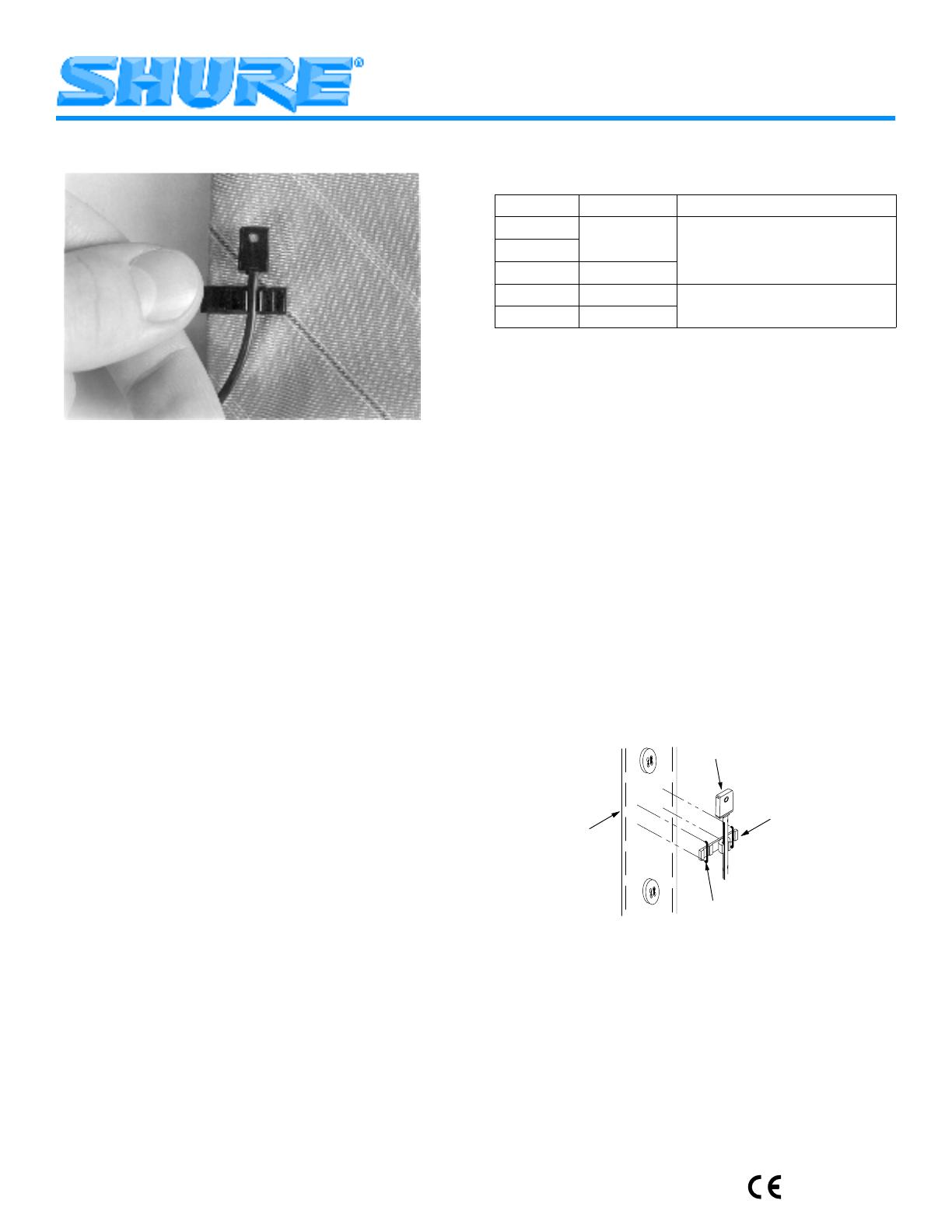
Sew-On Bracket. Sew the supplied sew-on mounting
bracket directly to a garment (Figure1). Use dark or light
thread as necessary to match the color of the the bracket.
GARMENT
MICROPHONE
BRACKET
THREAD
SEW–ON MOUNTING
FIGURE 1
MOUNTING THE SM93 PREAMPLIFIER
Use the spring-loaded belt clip to hold the amplifier to a
belt, skirt or trouser waistband, or inside pocket.
WINDSCREENS
An acoustic foam windscreen is supplied to help reduce
undesirable wind noise associated with outdoor miking.
Models WL93 and SM93 User Guide
27C3106 (CG)
2003, Shure Incorporated
Printed in U.S.A.
2
POWERING THE SM93 PREAMPLIFIER
Power the preamplifier supplied with the SM93 using any
phantom supply providing 11 to 52 Vdc, such as the Shure
Model PS1A Power Supply.
SM93 PREAMPLIFIER IMPEDANCE
Use a minimum load impedance of 800 or greater for
maximum signal handling and minimum distortion. Load as
low as 150 can be used, but a reduction in output clipping
level will result. Note that the power supply itself may add
loading (3300 in the Shure PS1A) to the microphone.
USING OTHER PREAMPLIFIERS OR BODY–PACKS
If connecting the 93 microphone to anything OTHER than
a Shure wireless body-pack or the preamplifier supplied with
the SM93, make sure it provides a regulated +5 Vdc source
(40 mA minimum) at pin 2 of the microphone connector, as
shown in Figure 2.
CONDENSER
CARTRIDGE
IMPEDANCE
CONVERTER
G
SHIELD
BLK
RED
S
D+
4
1
2
3
MICROPHONE WIRING DIAGRAM
FIGURE 2
SPECIFICATIONS
WL93 MICROPHONE (with standard test circuit
shown in Figure 3)
SM93 MICROPHONE (with preamplifier)
Type Condenser (electret bias) Condenser (electret bias)
Frequency Response (Figure 4) 50 to 20,000 Hz 80 to 20,000 Hz, 12 dB/octave rolloff below 100 Hz
Polar Pattern Omnidirectional, uniform with frequency Omnidirectional, uniform with frequency
Output Impedance 3000 Rated at 150 (90 actual)
Recommended minimum load impedance: 800
(May be used with loads as low as 150 with reduced
clipping level)
Output Level
(1 Pascal = 94 dB SPL)
Open Circuit Voltage: –38 dBV/Pa
(13 mV)
Open Circuit Voltage: –43 dBV/Pa (7.0 mV)
Output Clipping Level
(at 1,000 Hz)
0.25 V at 120 dB –18 dBV (0.13 V) minimum
Total Harmonic Distortion Less than 1% at 120 dB Less than 1% at 120 dB
Maximum SPL 120 dB 120 dB
Dynamic Range (maximum SPL
to A-weighted noise level)
102 dB 98 dB
Output Noise (equivalent SPL) 18 dB typical, A-weighted 22 dB typical, A-weighted
26 dB, weighted per DIN 45 405
Hum Pickup (electromagnetic) N/A –4 dB equivalent SPL in a 1 mOe field (60 Hz)
Signal-to-Noise Ratio 76 dB at 94 dB SPL (IEC 651) 72 dB at 94 dB SPL (IEC 651)
Polarity Positive pressure on microphone diaphragm
produces positive voltage on pins 3 and 4 with
respect to pin 1 (ground)*
Positive pressure on microphone diaphragm produces
positive voltage on pin 2 relative to pin 3 of preamplifier
output cable connector
Recommended Operating
Voltage
2 to 10 V; 5 V nominal (pin 2 to pins 3 and 4) 11 to 52 Vdc phantom. Protected against reverse
voltage application
Current Drain
40 mA typical
0.33 mA
Environmental Conditions Operating Temperatures: –18
o
to 57
o
C
(0
o
to 135
o
F)
Storage Temperatures: –29
o
to 74
o
C
(–20
o
to 165
o
F)
Operating Temperatures: –18
o
to 57
o
C (0
o
to 135
o
F)
Storage Temperatures: –29
o
to 74
o
C (–20
o
to 165
o
F)
Cable Black 1.27 m (4.17 ft), attached, two-conductor,
shielded, terminated by miniature connector type
TA4F (WL93T: Tan 1.27 m [4.17 ft])
Black 1.27 m (4.17 ft), attached, two-conductor,
shielded, terminated by miniature connector type
(TA4F)
Case Microphone: Black ABS thermoplastic case with
stainless-steel-mesh grille
Microphone: Black ABS thermoplastic case with
stainless-steel-mesh grille
P lifi St l ith fl ti bl k
Preamplifier: Steel case with non–reflective black
finish, black–chrome belt clip
Net Weight Microphone: 16 g (0.57 oz)
Microphone: 16 g (0.57 oz)
g
Preamplifier: 118 g (4.17 oz)
* Produces positive voltage at pin 2 of Shure L4/EC4 wireless receiver three–pin connector.
3
FURNISHED ACCESSORIES
Preamplifier (SM93) 90A4360. . . . . . . . . . . . . . . . . . . . . . .
Black Windscreen (WL93, SM93) RK355WS*. . . . . . . . . .
Black Tie Clip Assembly (WL93, SM93) RK354SB*. . . . .
Dual Black Tie Clip Assembly (SM93) RK307DB. . . . . . .
Tan Windscreen (WL93T) RK304T**. . . . . . . . . . . . . . . . .
Tan Tie Clip Assembly (WL93T) RK304T**. . . . . . . . . . . .
Black Sew-on Mounting Bracket (WL93, SM93) 65B1733. .
Tan Sew-on Mounting Bracket (WL93T) 65B1733A. . . .
Zippered Carrying Bag 26A13. . . . . . . . . . . . . . . . . . . . . . .
* Replacements furnished in multiples of 4.
** RK304 includes 2 tie clips and 2 windscreens.
OPTIONAL ACCESSORIES
In-Line On/Off Switch WA360. . . . . . . . . . . . . . . . . . . . . . .
CERTIFICATION
Eligible to bear CE Marking. Conforms to European EMC
Directive 89/336/EEC. Meets applicable tests and perfor-
mance criteria in European Standard EN 55103 (1996) parts
1 and 2, for residential (E1) and light industrial (E2) environ-
ments.
1
2
4
3
+5V
20 K
V out
2.2 mF
TEST CIRCUIT
FIGURE 3
500 1,000 2,000 5,000 10,000 20,00050 100 20020
0
+10
–10
SM93
dB
Hz
TYPICAL FREQUENCY RESPONSE
FIGURE 4
0.23 IN.
(5.84 mm)
0.24 IN.
(6.10 mm)
0.37 IN
(9.40 mm)
0.15 IN.
(3.81 mm)
(1–1/16 IN.)
27 mm
(3–29/32 IN.)
18.8 mm
(3/4 IN.)
SM93 PREAMPLIFIER
SM93/WL93 MICROPHONE
98.8 mm
OVERALL DIMENSIONS
FIGURE 5
4.1V
86B429
D1
R2
C
C3
1
3
2
P1
L1
2
.6V
.1V
.05V
3.5V
D2
86A415
Q1
86A348
R1
R6
C5
33K
Q2
86A350
150 pF
24K
R5
62K
150 pF
C8
C7
1.9V
.1V
B
C6
R4
360K
.047,5%
33X6.3
.047,5%
.05V
BRN
C2
C1
L2
3
1
150 pF
150 pF
YEL
GRNBLK
WHT
1. ALL RESISTORS 5%,1/8 WATT, UNLESS OTHERWISE SPECIFIED.
A
NOTES:
2. ALL NON–POLAR CAPACITORS IN µF, TOLERANCE 10% AND 50 VOLTS OR MORE
UNLESS OTHERWISE SPECIFIED. POLARIZED CAPACITORS SHOWN IN µF x VOLTS.
T1
D.C. VOLTAGE
A.C. VOLTAGE
3. D.C. VOLTAGES MEASURED WITH 11 MEG INPUT VOLTMETER; A.C. VOLTAGE MEA-
SURED WITH 1 MEG INPUT VOLTMETER. VALUES SHOWN ARE TYPICAL AND MAY
VARY ± 20%.
4. THE FOLLOWING SYMBOLS DENOTE:
CASE GROUND
CIRCUIT BOARD GROUND
1
3
2
RED
BLK
GRN
4
P2
5. POWER SOURCE IS 21 VDC THROUGH TWO 1.691 KOHM, 1% RESISTORS FROM
SUPPLY TO PINS 2 AND 3 OF CONNECTOR P1.
6. INPUT SIGNAL OF 0.1V AT 2 KHZ
APPLIED TO CIRCUIT BELOW:
.1V
A
B
C
18K
1.2K
10x10
SM93 PREAMPLIFIER CIRCUIT DIAGRAM
FIGURE 6
12
BLINDAGE
ABSCHIRMUNG
BLINDAJE
SCHERMATURA
SCHÉMA DE CÂBLAGE DU MICROPHONE
MIKROFONSCHALTPLAN
DIAGRAMA DE ALAMBRADO DEL MICROFONO
SCHEMA CIRCUITALE DEL MICROFONO
FIGURE 2
500 1,000 2,000 5,000 10,000 20,00050 100 20020
0
+10
–10
SM93
dB
Hz
RÉPONSE EN FRÉQUENCE TYPIQUE
TYPISCHER FREQUENZGANG
RESPUESTA DE FRECUENCIA TIPICA
RISPOSTA IN FREQUENZA TIPICA
FIGURE 3
0.23 IN.
(5.84 mm)
0.24 IN.
(6.10 mm)
0.37 IN
(9.40 mm)
0.15 IN.
(3.81 mm)
(1–1/16 IN.)
27 mm
(3–29/32 IN.)
18.8 mm
(3/4 IN.)
SM93 PREAMPLIFIER
SM93/WL93 MICROPHONE
98.8 mm
DIMENSIONS HORS TOUT S GESAMTABMESSUNGEN S DIMENSIONES GENERALES S DIMENSIONI COMPLESSIVE
FIGURE 4
4.1V
86B429
D1
R2
C
C3
1
3
2
P1
L1
2
.6V
.1V
.05V
3.5V
D2
86A415
Q1
86A348
R1
R6
C5
33K
Q2
86A350
150 pF
24K
R5
62K
150 pF
C8
C7
1.9V
.1V
B
C6
R4
360K
.047,5%
33X6.3
.047,5%
.05V
BRN
C2
C1
L2
3
1
150 pF
150 pF
YEL
GRNBLK
WHT
1. ALL RESISTORS 5%,1/8 WATT, UNLESS OTHERWISE SPECIFIED.
A
NOTES:
2. ALL NON–POLAR CAPACITORS IN µF, TOLERANCE 10% AND 50 VOLTS OR MORE
UNLESS OTHERWISE SPECIFIED. POLARIZED CAPACITORS SHOWN IN µF x VOLTS.
T1
D.C. VOLTAGE
A.C. VOLTAGE
3. D.C. VOLTAGES MEASURED WITH 11 MEG INPUT VOLTMETER; A.C. VOLTAGE MEA-
SURED WITH 1 MEG INPUT VOLTMETER. VALUES SHOWN ARE TYPICAL AND MAY
VARY ± 20%.
4. THE FOLLOWING SYMBOLS DENOTE:
CASE GROUND
CIRCUIT BOARD GROUND
1
3
2
RED
BLK
GRN
4
P2
5. POWER SOURCE IS 21 VDC THROUGH TWO 1.691 KOHM, 1% RESISTORS FROM
SUPPLY TO PINS 2 AND 3 OF CONNECTOR P1.
6. INPUT SIGNAL OF 0.1V AT 2 KHZ
APPLIED TO CIRCUIT BELOW:
.1V
A
B
C
18K
1.2K
10x10
SCHÉMA DE PRINCIPE DU PRÉAMPLIFICATEUR SM93 S STROMLAUFPLAN FÜR VORVERSTÄRKER SM93 S DIAGRAMA
ESQUEMATICO DEL PREAMPLIFICADOR SM93 S SCHEMA CIRCUITALE DEI MODELLI DEL PREAMPLIFICATORE SM93
FIGURE 5
1
2
4
3
+5V
20 K
V out
2.2 mF
CIRCUIT D’ESSAI S PRÜFSCHALTUNG S CIRCUITO DE
PRUEBA S CIRCUITO DI PROVA
FIGURE 6
SHURE Incorporated Web Address: http://www.shure.com
5800 W. Touhy Avenue, Niles, IL 60714-4608, U.S.A.
Phone: 800-257-4873 Fax: 847-600-1212
In Europe, Phone: 49-7131-72140 Fax: 49-7131-721414
In Asia, Phone: 852-2893-4290 Fax: 852-2893-4055
Elsewhere, Phone: 847-600-2000 Fax: 847-600-8446
  • Page 1 1
  • Page 2 2
  • Page 3 3
  • Page 4 4
  • Page 5 5
  • Page 6 6
  • Page 7 7
  • Page 8 8
  • Page 9 9
  • Page 10 10
  • Page 11 11
  • Page 12 12

Shure MICROPHONE WL93 User manual

Category
Microphones
Type
User manual
This manual is also suitable for

Ask a question and I''ll find the answer in the document

Finding information in a document is now easier with AI