Electrolux EI36EC45KS Installation guide

Category
Ovens
Type
Installation guide

This manual is also suitable for

1
ELECTRIC COOKTOP INSTALLATION INSTRUCTIONS
3 1/8
(7,9)
5 5/8
(14,3)
3 ½
(8,9)
7 ½
(19,1)
6 5/8
(16,8)
A
I
B
C
G
H
30” Min. *
(76.2 cm)
E
F
D
All dimensions are in inches (cm).
P/N 318205426 (1202) Rev. B
English – pages 1-6
Español – pages 7-12
Français - pages 13-18
Notes - pages 19-20
Cooktop Dimensions
IMPORTANT INSTALLATION INFORMATION
•Allelectriccooktopsrunoffasinglephase,three-wireor
four-wirecable,240/208volt,60hertz,AConlyelectrical
supplywithground.
•Minimumdistancebetweencooktopandoverheadcabinetry
is 30” (76.2 cm).
*30”(76.2cm)min.forunprotectedcabinet
24”(61cm)min.forprotectedsurface
CooktopCutout
Dimensions
Figure 1
Printed in Canada
4” X 8(10.2 cm x 20.3 cm)
openingtoroutearmoredcable
ifapanelispresent
Front Rear
Sideview
Countertop
Countertop
INSTALLATION AND SERVICE MUST BE PERFORMED
BY A QUALIFIED INSTALLER.
IMPORTANT: SAVE FOR LOCAL ELECTRICAL INSPECTOR’S USE.
READ AND SAVE THESE INSTRUCTIONS FOR FUTURE REFERENCE.
WARNING
FOR YOUR SAFETY: Do not store or use gasoline or other
flammable vapors and liquids in the vicinity of this or any other appliance.
Canada United States
PRODUCT DIMENSIONS
MODEL A. WIDTH B. DEPTH C. HEIGHT D. HEIGHT E. BOX WIDTH F. BOX DEPTH
30’CeramicModel 30¾ (78.1) 21¾ (55.2) 3 1/8 (7.9) 6 5/8 (16.8) 28 5/8 (72.7) 19¼ (48.9)
36’’CeramicModel 36¾ (93.3) 21¾ (55.2) 3 1/8 (7.9) 6 5/8 (16.8) 34 5/8 (87.9) 19¼ (48.9)
CUT OUT DIMENSIONS
MODEL
G. WIDTH H. DEPTH I. HEIGHT BELOW
COOKTOP
MINIMUM MAXIMUM MINIMUM MAXIMUM
30’CeramicModel 29¾ (75.6) 30 (76.2) 20 3/8 (51.8) 20 5/8 (52.4) 8½ (21.6)
36’’CeramicModel 35¾ (90.8) 36 (91.4) 20 3/8 (51.8) 20 5/8 (52.4) 8½ (21.6)
2
ELECTRIC COOKTOP INSTALLATION INSTRUCTIONS
I
H
G
A
Figure2–COUNTERTOPCUTOUTOPENING
CAUTION
Toeliminatetheriskofburnsor
rebyreachingoverheatedsurfaces,cabinet
storagespacelocatedabovethecooktopshould
beavoided.Ifcabinetstorageisprovided,risk
canbereducedbyinstallingarangehoodthat
projectshorizontallyaminimumof5”(12.7cm)
beyondthebottomofthecabinets.
LettersonthisgurerefertochartonfrontpageexceptforJ , K & L.
OverheadCabinetShouldNotExceeda
MaximumDepthof13”(33cm)
30”(76.2cm)Min.
ClearanceBetweenthe
TopoftheCooking
PlatformandtheBottom
ofanUnprotectedWood
orMetalCabinet.
24”(61cm)Min.when
BottomofWoodorMetal
CabinetisProtectedby
Not Less Than 1/8” (0.3
cm) Flame Retardant
MillboardCoveredWith
Not Less Than No. 28
MGSSheetSteel,0.015”
(0.4 mm) Stainless
Steel,0.024”(0.6mm)
Aluminumor0.020”(0.5
mm) Copper.
21/2”(6.4cm)Min.FromEdge
ofCutouttoFrontEdgeof
Countertop
18”
(45.7 cm)
J Min.FromEdgeof
Cooktop to Nearest
CombustibleWall
(EitherSideofUnit).
12”
(30.5 cm)
10”
( 25.4 cm)
KMin.Recommended
DistanceBetweenRear
EdgeofCutoutand
NearestCombustible
SurfaceAbove
Countertop
24”
(61 cm)
Installjunctionboxata
locationwhichwillbeeasy
toreachandthatwillnot
interferewiththecooktop
installation.Wesuggest
12”(30.48cm)lowerthan
thecountertop.
Ifadrawerispresent
underneath,allowatleast
10”(25.4cm)ofclearance
belowthecountertop.
CAUTION
Never store
ammableproductsinthe
drawer.
L
Min.
MODEL J K L
30’’ (76.2 cm) 2’’ (5.1 cm) 2’’ (5.1 cm) 30’’ (72.6 cm)
36’’ (91.4 cm)
2’’ (5.1 cm) 2’’ (5.1 cm) 36’’ (91.4 cm)
3
ELECTRIC COOKTOP INSTALLATION INSTRUCTIONS
Onlycertaincooktopmodelsmaybeinstalledover
certainbuilt-inelectricovenmodels.Approved
cooktopsandbuilt-inovensarelistedbytheMFG
IDnumberandproductcode(seetheinsertsheet
includedintheliteraturepackageandcooktop
installationinstructionsfordimensions).
36”Min.
(91.4cm)Min.
Use3/4”(1.9cm)plywood,
installedontworunners,ush
withtoeplate.Basemustbe
capableofsupporting150
pounds(68kg)for27”models
and200pounds(90kg)for
30” models.
Cutanopeninginwoodbaseminimum
4”x4”(10.2X10.2cm),2”(5cm)from
leftsidellerpanel,toroutearmoured
cabletojunctionbox.
*Ifnocooktopisinstalleddirectlyovertheovenunit,5”(12.7cm)maximumisallowedabovetheoor.
208/240Voltjunctionbox
forbuilt-inoven.
TYPICAL UNDER COUNTER INSTALLATION OF A SINGLE ELECTRIC BUILT-IN OVEN
WITH AN ELECTRIC COOKTOP MOUNTED ABOVE
Approx. 3”
(7.5 cm)
Cabinetsideller
panelsarenecessaryto
isolatetheunitfrom
adjoiningcabinets.
Cabinetsideller
heightshouldallowfor
installationofapproved
cooktop models
To reduce the risk of
personal injury and
tipping of the wall
oven, the wall oven
must be secured to
the cabinet (s) by
mounting brackets.
4½” (11.5 cm)
Max.*
For typical under counter installation of an electric built-in oven with an electric cooktop over.
Approx. 3”
(7.5 cm)
See
Note 1
Note 1:4”x4”(10.2X10.2cm)openingtoroute
armouredcablefromcooktoptojunctionbox.
208/240Volt
junctionbox
forCooktop
Unitwill
overlap
cutout
(minimum)
edgesby
1” (2.5cm)
CUTOUT DIMENSIONS
F. WIDTH G. DEPTH H. HEIGHT
27’’ (68.6 cm)
Wall Oven
24 7/8’(63.2cm)Min.
25¼’’(64.1cm)Max.
23½’’ (59.7 cm)
27¼’(69.2cm)Min.
28¼’(71.8cm)Max.
30’’ (76.2 cm)
Wall Oven
28½’(72.4cm)Min.
29’’(73.7cm)Max.
23½’’ (59.7 cm)
27¼’(69.2cm)Min.
28¼’(71.8cm)Max.
4
ELECTRIC COOKTOP INSTALLATION INSTRUCTIONS
Important Notes to the Installer
1. Readallinstructionscontainedintheseinstallation
instructionsbeforeinstallingthecooktop.
2. Removeallpackingmaterialbeforeconnectingthe
electricalsupplytothecooktop.
3. Observeallgoverningcodesandordinances.
4. Besuretoleavetheseinstructionswiththeconsumer.
Important Note to the Consumer
KeeptheseinstructionswithyourUseandCareGuidefor
futurereference.
IMPORTANT SAFETY
INSTRUCTIONS
Be sure your cooktop is installed and grounded
properly by a qualified installer or service
technician.
•These cooktops must be electrically grounded in
accordance with local codes or, in their absence,
with the National Electrical Code ANSI/NFPA No.
70—latest edition in the United States, or with
CSA Standard C22.1, Canadian Electrical Code,
Part 1, in Canada.
WARNING
The electrical power to the cooktop
must be shut off while line connections are being
made. Failure to do so could result in serious injury
or death.
Provide Electrical Connection
Installthejunctionboxunderthecabinetandrun
120/240or120/208Volt,ACwirefromthemain
circuitpanel.NOTE:DONOTconnectthewiretothe
circuitpanelatthistime.Waituntilallwireshavebeen
connectedinthejunctionbox.
Electrical Requirements
Observe all governing codes and local ordinances.
1. A3-wireor4-wiresinglephase120/240or120/208
Volt,60HzAConlyelectricalsupplyisrequiredona
separatecircuitfusedonbothsidesoftheline(time-
delayfuseorcircuitbreakerisrecommended,40Aor
50A).DONOTfuseneutral.
NOTE:Wiresizesandconnectionsmustconformwith
thefusesizeandratingoftheapplianceinaccordance
withtheNationalElectricalCodeANSI/NFPANo.70–
latestedition,orwithCSAstandardC22.1,Canadian
ElectricalCode,Part1,andlocallocalcodesand
ordinances.
WARNING
An extension cord must not be used
with this appliance. Such use may result in a fire,
electrical shock, or other personal injury.
2. Theapplianceshouldbeconnectedtothefused
disconnect(orcircuitbreaker)boxthroughexible
armoredornonmetallicsheathedcable.Theexible
armoredcableextendingfromthisapplianceshould
beconnecteddirectlytothegroundedjunctionbox.
Thejunctionboxshouldbelocatedasshownin
Figure3withasmuchslackaspossibleremainingin
thecablebetweentheboxandtheappliance,soit
canbemovedifservicingisevernecessary.
3. Asuitablestrainreliefmustbeprovidedtoattach
theexiblearmoredcabletothejunctionbox.
Unpacking Instructions
1. Unpackandvisuallyinspectthecooktop
2. Besurethebottleofcleanerconditionerpacked
intheliteraturebagisleftwheretheusercan
nditeasily.Itisimportantthattheceramic-glass
smoothtopbepretreatedbeforeuseseeCooktop
Cleaning and Maintenance section in the Use and
Care Guide.
Model and Serial Number Location
Theserialplateislocatedunderthecooktop.
Whenorderingpartsforormakinginquiresaboutyour
cooktop,alwaysbesuretoincludethemodelandserial
numbersandalotnumberorletterfromtheserialplate
onyourcooktop.
Figure3
5
ELECTRIC COOKTOP INSTALLATION INSTRUCTIONS
Electrical connection
Itistheresponsibilityandobligationoftheconsumerto
contactaqualiedinstallertoassurethattheelectrical
installationisadequateandisinconformancewiththe
NationalElectricalCodeANSI/NFPANo.70-latestedition,
orwithCSAStandardC22.1,CanadianElectricalCode,
Part1,andlocalcodesandordinances.
Risk of electrical shock (Failure to
heed this warning may result in electrocution or
other serious injury.) This appliance is equipped
with copper lead wire. If connection is made to
aluminum house wiring, use only connectors that
are approved for joining copper and aluminum wire
in accordance with the National Electrical Code
and local code and ordinances. When installing
connectors having screws which bear directly on
the steel and/or aluminum flexible conduit, do no
tighten screws sufficiently to damage theexible
conduit. Do not over bend or excessively distort
flexible conduit to avoid separation of convolutions
en exposure of internal wires.
DONOTgroundtoagassupplypipe.DONOTconnect
toelectricalpowersupplyuntilapplianceispermanently
grounded.Connectthegroundwirebeforeturningon
thepower.
(If your appliance is equipped with a
white neutral conductor.)
This appliance is manufactured with a white neutral
power supply and a frame connected copper wire.
The frame is grounded by connection of grounding
lead to neutral lead at the termination of the
conduit, if used in USA, in a new branch circuit
installation (1996 NEC), mobile home, recreational
vehicles, where local code do not permit grounding
trough the neutral (white) wire or in Canada,
disconnect the white and green lead from each
other and use ground lead to ground unit in
accordance with local codes, connect neutral lead
to branch circuit-neutral conductor in usual manner
see Figure 5. If your appliance is to be connected
to a 3 wire grounded junction box (US only),
where local code permit connecting the appliance-
grounding conductor to the neutral (white) see
Figure 4.
NOTE TO ELECTRICIAN:Thearmoredcableleads
suppliedwiththeapplianceareUL-recognizedfor
connectiontolargergaugehouseholdwiring.The
insulationoftheleadsisratedattemperaturesmuch
higherthantemperatureratingofhouseholdwiring.The
currentcarryingcapacityoftheconductorisgovernedby
thetemperatureratingoftheinsulationaroundthewire,
ratherthanthewiregaugealone.
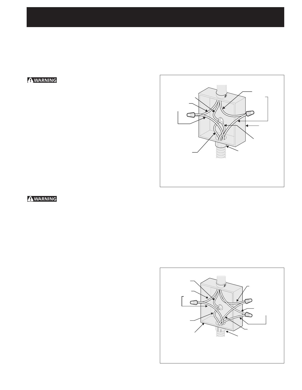
Where local codes permit connecting the appliance-
grounding conductor to the neutral (white) wire
(US Only) (seegure 4):
1. Disconnectthepowersupply.
2. Inthejunctionbox:
Connectapplianceandpowersupplycablewiresas
showninFigure4.
Figure 4
3-WIRE GROUNDED JUNCTION BOX
CablefromPowerSupply
Black
Wires
Junction
Box
Cablefromappliance
GroundWire
(Bare or Green Wire)
White Wire
(Neutral)
U.L.-ListedConduit
Connector (or CSA listed)
Red
Wires
White Wire
(Neutral)
Figure 5
4-WIRE GROUNDED JUNCTION BOX
CablefromPowerSupply
White Wire
JunctionBox
Cablefrom
appliance
White Wire
Black
Wires
Red
Wires
GroundWire
GroundWire
(Bare or Green
Wire)
U.L.-ListedConduit
Connector (or CSA
listed)
If the appliance is used in a new branch circuit
installation (1996 NEC), mobile home, recreational
vehicle, or where local codes DO NOT permit
grounding through the neutral (white) wire, the
appliance frame MUST NOT be connected to the
neutral wire of the 4-wire electrical system. (see
figure 5):
1. Disconnectthepowersupply.
2. Separatethegreen(orbarecopper)andwhite
appliancecablewires.
3.Inthejunctionbox:
Connectapplianceandpowersupplycablewiresas
showninFigure5.
6
ELECTRIC COOKTOP INSTALLATION INSTRUCTIONS
Cooktop Installation
1. Visuallyinspectthecooktopfordamage.Alsomake
sureallcooktopscrewsaretight(seeFigure6).
3. Setthecooktopintothecountertopcutout.
NOTE:Donotusecaulkingcompound;cooktopshould
beremovableforservicewhenneeded.
WARNING
Do not remove the nylon spacers on
the edges of the cooktop. These spacers center the
cooktop in the space provided. The cooktop must
be centered to prevent excess heat buildup that
may result in heat damage or fire (see Figure 8).
2.Installtheretainerbrackets.SeeFigure7
The retainer brackets MUST be installed, to meet
local codes or, in their absence, with the National
Electrical Code ANSI/NFPA No. 70—latest edition
in the United States, or with CSA Standard C22.1,
Canadian Electrical Code, Part 1 in Canada (see
Figure 7).
Screws
Figure6
Figure7
Cooktop
Nylon
spacer
Countertop
Retainerbracket
Figure8
6Nylonspacers
2 Retainer
brackets
Positionbrackets
onunitcutout
center line
Granite countertop Installation Kit
AGraniteCountertopInstallationkit#903061-9010can
beorderedthroughaServiceCenterorbyphoneat1-877-
ELECTROLUX (1-877-435-3287).
Checking Operation
RefertotheUse and Care Guideforoperation.
CAUTION
Donottouchcooktopglassorelements.
Theymaybehotenoughtoburnyou.
Model and Serial Number Location
Theserialplateislocatedunderthecooktop.
Whenorderingpartsforormakinginquiresaboutyour
cooktop,alwaysbesuretoincludethemodelandserial
numbersandalotnumberorletterfromtheserialplate
onyourcooktop.
Before you Call for Service
ReadtheBeforeYouCallforServiceChecklistand
operatinginstructionsinyourUseandCareGuide.
Itmaysaveyoutimeandexpense.Thisincludes
commonoccurencesthatarenottheresultofdefective
workmanshipormaterialsinthisappliance.
RefertoyourUse and Care Guideforsevicephonenum-
bers.
7
INSTRUCCIONES PARA LA INSTALACIÓN DE LA ESTUFA ELÉCTRICA
3 1/8
(7,9)
5 5/8
(14,3)
3 ½
(8,9)
7 ½
(19,1)
6 5/8
(16,8)
A
I
B
C
G
H
30” Min. *
(76.2 cm)
E
F
D
Todas las dimensiones se dan en pulgadas (cm).
P/N 318205426 (1202) Rev. B
English – pages 1-6
Español – pages 7-12
Français - pages 13-18
Notas - pages 19-20
INFORMACIÓN IMPORTANTE PARA LA INSTALACION
• Todaslasestufaseléctricasfuncionanconunaalimentacióneléctricacon
puestaatierradefasesingular,3o4alambres,240/208voltios,60hertz
ysóloAC.
• Favordenotarqueladistanciamínimaentrelasuperciedelaestufay
losgabinetesadyacentesyporencimasonde30"(76.2cm).
* 30"(76.2cm)mín.paraungabinetedesprotegido.
24"(61cm)mín.paraunasupercieprotegida.
Figura 1
DimensionesdelaEstufa
Dimensiones del
RecortadodelaEstufa
ImpresoenCanada
4"X8"(10.2cmX
20.3 cm) apertura
paraelcablesi
existe un panel.
Parte delantera Parte trasera
Vista de lado
Mostrador
Mostrador
LA INSTALACIÓN Y EL SERVICIO DEBEN SER EFECTUADOS POR
UN INSTALADOR CALIFICADO.
IMPORTANTE: GUARDE ESTAS INSTRUCCIONES PARA USO DEL
INSPECTOR LOCAL DE ELECTRICIDAD.
LEA Y GUARDE ESTAS INSTRUCCIONES PARA REFERENCIA FUTURA.
PARA SU SEGURIDAD: No amanece ni utilice gasolina u otros
vapores y líquidos inflamables en la proximidad de este o de cualquier otro
artefacto.
Canadá Estados Unidos
DIMENSIONES DE LA ESTUFA
MODELO A. ANCHURA B. PROFUNDIDAD C. ALTURA D. ALTURA E. ANCHODELACAJA F. PROFUNDIDADDELA
CAJA
MODELO30’ 30¾ (78.1) 21¾ (55.2) 3 1/8 (7.9) 6 5/8 (16.8) 28 5/8 (72.7) 19¼ (48.9)
MODELO36’ 36¾ (93.3) 21¾ (55.2) 3 1/8 (7.9) 6 5/8 (16.8) 34 5/8 (87.9) 19¼ (48.9)
DIMENSIONES DE RECORTADO
MODELO
G. ANCHURA H. PROFUNDIDAD I.ALTURADEBAJO
DELAESTUFA
MÍNIMA MÁXIMA MÍNIMA MÁXIMA
MODELO30’ 29¾ (75.6) 30 (76.2) 20 3/8 (51.8) 20 5/8 (52.4) 8½ (21.6)
MODELO36’ 35¾ (90.8) 36 (91.4) 20 3/8 (51.8) 20 5/8 (52.4) 8½ (21.6)
19
INSTRUCTIONS D'INSTALLATION POUR PLAQUE DE CUISSON ÉLECTRIQUE
Notes
20
INSTRUCTIONS D'INSTALLATION POUR PLAQUE DE CUISSON ÉLECTRIQUE
Notes
  • Page 1 1
  • Page 2 2
  • Page 3 3
  • Page 4 4
  • Page 5 5
  • Page 6 6
  • Page 7 7
  • Page 8 8
  • Page 9 9
  • Page 10 10
  • Page 11 11
  • Page 12 12
  • Page 13 13
  • Page 14 14
  • Page 15 15
  • Page 16 16
  • Page 17 17
  • Page 18 18
  • Page 19 19
  • Page 20 20

Electrolux EI36EC45KS Installation guide

Category
Ovens
Type
Installation guide
This manual is also suitable for

Ask a question and I''ll find the answer in the document

Finding information in a document is now easier with AI