Page is loading ...

1
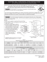
ELECTRIC COOKTOP INSTALLATION INSTRUCTIONS
Cooktop Dimensions
IMPORTANT INSTALLATION INFORMATION
• Allelectriccooktopsrunoasinglephase,three-wire
orfour-wirecable,240/208volt,60hertz,AConly
electricalsupplywithground.
• Pleasenoteminimumdistancebetweencooktopand
adjacentandoverheadunprotectedcabinetryis30"
(76.2cm).
*30"(76.2cm)min.forunprotectedcabinet.
24"(61cm)min.forprotectedsurface.
Cooktop Cutout
Dimensions
Figure 1 - 30" Model shown only
Alldimensionsareininches(cm).
PrintedinChina
P/NA01705001(1607)Rev.A
English–pages1-8
Español–pages9-16
Français–pages17-24
4"X8"(10.2cmx20.3cm)opening
attherightreartoroutearmored
cableifapanelispresent.
WARNING
Thecornersofthisunitare
fragile.Carefullyinstallthecooktopby
itssides.Wheninstalling,neverletthe
weightoftheunitrestonanyonecorner.
INSTALLATION AND SERVICE MUST BE PERFORMED BY A QUALIFIED INSTALLER.
IMPORTANT: SAVE FOR LOCAL ELECTRICAL INSPECTOR'S USE.
READ AND SAVE THESE INSTRUCTIONS FOR FUTURE REFERENCE.
WARNING
FOR YOUR SAFETY: Do not store or use gasoline or other ammable vapors
and liquids in the vicinity of this or any other appliance.
PRODUCT DIMENSIONS
MODEL A. WIDTH B. DEPTH C
1
. HEIGHT C
2
. HEIGHT D. BOX WIDTH E. BOX DEPTH
30"CeramicModel
30¾(78.1) 21½(54.6) 5½(14) 3¼(8.3) 29(73.7) 19½(49.5)
36"CeramicModel
36¾(93.3) 21½(54.6) 5½(14) 3¼(8.3) 345/8(87.9) 19½(49.5)
CUT OUT DIMENSIONS
MODEL F. WIDTH G. DEPTH H. HEIGHT BELOW
COOKTOP
MINIMUM MAXIMUM MINIMUM MAXIMUM
30"CeramicModel
29¾(75.6) 301/8(76.5) 203/8(51.8) 20¾(52.7) 6(15.2)
36"CeramicModel
35½(90.2) 357/8(91.1) 203/8(51.8) 20¾(52.7) 6(15.2)

2
ELECTRIC COOKTOP INSTALLATION INSTRUCTIONS
Figure 2 – COUNTERTOP CUTOUT OPENING
CAUTION
Toeliminatetheriskofburnsorreby
reachingoverheatedsurfaces,cabinetstoragespace
locatedabovethecooktopshouldbeavoided.Ifcabinet
storageisprovided,riskcanbereducedbyinstallinga
rangehoodthatprojectshorizontallyaminimumof5"
(12.7cm)beyondthebottomofthecabinets.
LettersonthisgurerefertochartonfrontpageexceptforI.
OverheadCabinetShouldNotExceed
aMaximumDepthof13"(33cm)
30"(76.2cm)Min.
ClearanceBetween
theTopoftheCooking
PlatformandtheBottom
ofanUnprotected
WoodorMetalCabinet.
24"(61cm)Min.when
BottomofWood
orMetalCabinetis
ProtectedbyNot
LessThan1/8"Flame
RetardantMillboard
CoveredWithNot
LessThanNo.28MGS
SheetSteel,0.015"
(0.4mm)Stainless
Steel,0.024"(0.6mm)
Aluminumor0.020"
(0.5mm)Copper
21/2"(6.4cm)Min.FromEdgeof
CutouttoFrontEdgeofCountertop
ApproximateLocation
ofJunctionBox
18"
(45.7cm)
Itisnotrecommendedtouse
drawerunderneathcooktop.
Emptyspaceisneededfor
installationpurpose.
7½"(19.1cm)
Min.FromEdge
of Cooktop
toNearest
Combustible
Wall(Either
SideofUnit).
12"
(30.5cm)
10"
(25.4cm)
2"(5.1cm)Min.
Recommended
DistanceBetween
RearEdgeof
CutoutandNearest
CombustibleSurface
AboveCountertop
24"
(61cm)
I
Min.
Model I
30"Model 30"(76.2cm)
36"Model 36"(91.4cm)

3
ELECTRIC COOKTOP INSTALLATION INSTRUCTIONS
Important Notes to the Installer
1. Readallinstructionscontainedintheseinstallation
instructionsbeforeinstallingthecooktop.
2. Removeallpackingmaterialbeforeconnectingthe
electricalsupplytothecooktop.
3. Observeallgoverningcodesandordinances.
4. Besuretoleavetheseinstructionswiththeconsumer.
Important Note to the Consumer
KeeptheseinstructionswithyourUseandCareGuidefor
futurereference.
IMPORTANT SAFETY
INSTRUCTIONS
• Be sure your cooktop is installed and grounded
properly by a qualied installer or service
technician.
• These cooktops must be electrically grounded in
accordance with local codes or, in their absence,
with the National Electrical Code ANSI/NFPA No.
70—latest edition in the United States, or with CSA
Standard C22.1, Canadian Electrical Code, Part 1, in
Canada.
WARNING
The electrical power to the cooktop must
be shut o while line connections are being made.
Failure to do so could result in serious injury or death.
Provide Electrical Connection
Installthejunctionboxunderthecabinetandrun
120/240or120/208Volt,ACwirefromthemain
circuitpanel.NOTE:DONOTconnectthewiretothe
circuitpanelatthistime.Waituntilallwireshavebeen
connectedinthejunctionbox.
Electrical Requirements
Observe all governing codes and local ordinances.
1. A3-wireor4-wiresinglephase120/240or120/208
Volt,60HzAConlyelectricalsupplyisrequired
onaseparatecircuitfusedonbothsidesofthe
line(a40Atime-delayfuseorcircuitbreakeris
recommended).DONOTfuseneutral.
NOTE:Wiresizesandconnectionsmustconformwith
thefusesizeandratingoftheapplianceinaccordance
withtheNationalElectricalCodeANSI/NFPANo.70–
latestedition,orwithCSAstandardC22.1,Canadian
ElectricalCode,Part1,andlocalcodesandordinances.
WARNING
An extension cord must not be used with
this appliance. Such use may result in a re, electrical
shock, or other personal injury.
2. Theapplianceshouldbeconnectedtothefused
disconnect(orcircuitbreaker)boxthroughexible
armoredornonmetallicsheathedcable.Theexible
armoredcableextendingfromthisapplianceshould
beconnecteddirectlytothegroundedjunctionbox.
Thejunctionboxshouldbelocatedasshownin
Figure2withasmuchslackaspossibleremainingin
thecablebetweentheboxandtheappliance,soit
canbemovedifservicingisevernecessary.
3. Asuitablestrainreliefmustbeprovidedtoattach
theexiblearmoredcabletothejunctionbox.
Observe all governing codes and local ordinances.
Unpacking Instructions
1. Leavecornersupportsoncooktopuntilcompletion
ofElectricalConnection.
2. Besurethebottleofcleanerconditionerpacked
in0theliteraturebagisleftwheretheusercan
nditeasily.Itisimportantthattheceramic-glass
smoothtopbepretreatedbeforeuse.SeeCeramic
Glass Cooktop Cleaning and Maintenance section
intheUse and Care Guide.
Figure 3

4
ELECTRIC COOKTOP INSTALLATION INSTRUCTIONS
Electrical connection
Itistheresponsibilityandobligationoftheconsumerto
contactaqualiedinstallertoassurethattheelectrical
installationisadequateandisinconformancewith
theNationalElectricalCodeANSI/NFPANo.70-
latestedition,orwithCSAStandardC22.1,Canadian
ElectricalCode,Part1,andlocalcodesandordinances.
WARNING
Risk of electrical shock (Failure to
heed this warning may result in electrocution or
other serious injury.) This appliance is equipped with
copper lead wire. If connection is made to aluminum
house wiring, use only connectors that are approved
for joining copper and aluminum wire in accordance
with the National Electrical Code and local code and
ordinances. When installing connectors having screws
which bear directly on the steel and/or aluminum
exible conduit, do no tighten screws suciently to
damage the exible conduit. Do not over bend or
excessively distort exible conduit to avoid separation
of convolutions en exposure of internal wires.
DONOTgroundtoagassupplypipe.DONOT
connecttoelectricalpowersupplyuntilapplianceis
permanentlygrounded.Connectthegroundwirebefore
turningonthepower.
WARNING
(If your appliance is equipped with a
white neutral conductor.)
This appliance is manufactured with a white neutral
power supply and a frame connected copper wire.
The frame is grounded by connection of grounding
lead to neutral lead at the termination of the conduit,
if used in USA, in a new branch circuit installation
(1996 NEC), mobile home, recreational vehicles, where
local code do not permit grounding trough the neutral
(white) wire or in Canada, disconnect the white and
green lead from each other and use ground lead to
ground unit in accordance with local codes, connect
neutral lead to branch circuit-neutral conductor in
usual manner see Figure 6 or 7. If your appliance is
to be connected to a 3 wire grounded junction box
(US only), where local code permit connecting the
appliance-grounding conductor to the neutral (white)
see Figure 4 or 5.
NOTE TO ELECTRICIAN:Thearmoredcableleads
suppliedwiththeapplianceareUL-recognizedfor
connectiontolargergaugehouseholdwiring.The
insulationoftheleadsisratedattemperaturesmuch
higherthantemperatureratingofhouseholdwiring.The
currentcarryingcapacityoftheconductorisgoverned
bythetemperatureratingoftheinsulationaroundthe
wire,ratherthanthewiregaugealone.
Figure 5
3-WIRE GROUNDED JUNCTION BOX
36" Models with Warmer Zone
CablefromPowerSupply
Black
Wires
JunctionBox
Cablefromappliance
GroundWire(Bare
orGreenWire)
WhiteWire
(Neutral)
U.L.-ListedConduit
Connector(orCSAlisted)
Red
Wires
WhiteWire
(Neutral)
Where local codes permit connecting the appliance-
grounding conductor to the neutral (white) wire:
If your cooktop has a 3-wire cable to be connected to
a 3-wire grounded junction box (see gure 4):
1. Disconnectthepowersupply.
2. Inthecircuitbreaker,fuseboxorjunctionbox:
connectapplianceandpowersupplycablewiresas
showningure4.
If your cooktop has a 4-wire cable to be connected to
a 3-wire grounded junction box (see gure 5):
1. Disconnectthepowersupply.
2. Inthecircuitbreaker,fuseboxorjunctionbox:
connectapplianceandpowersupplycablewiresas
showningure5.
Figure 4
3-WIRE GROUNDED JUNCTION BOX
CablefromPowerSupply
Black
Wires
JunctionBox
Cablefromappliance
Red
Wires
U.L.-ListedConduit
Connector(orCSA
listed)
GroundWire
(BareorGreenWire)
WhiteWire
(Neutral)

5
ELECTRIC COOKTOP INSTALLATION INSTRUCTIONS
If the appliance is used in a new branch circuit
installation (1996 NEC), mobile home, recreational
vehicle, or where local codes DO NOT permit
grounding through the neutral (white) wire, the
appliance frame MUST NOT be connected to the
neutral wire of the 4-wire electrical system.
If your cooktop has a 3-wire cable (see gure 6):
1. Disconnectthepowersupply.
2. Separatethegreen(orbarecopper)andwhite
appliancecablewires.
3. Capthewhitewirefromthepowersupplycableifa
3-wireappliancecableissupplied.
4.Inthecircuitbreaker,fuseboxorjunctionbox:
connectapplianceandpowersupplycablewiresas
showningure6.
If your cooktop has a 4 wire cable (see gure 7):
1. Disconnectthepowersupply.
2. Separatethegreen(orbarecopper)andwhite
appliancecablewires.
3.Inthecircuitbreaker,fuseboxorjunctionbox:
connectapplianceandpowersupplycablewiresas
showningure7.
WARNING
If connecting to a 4-wire power supply
cable electrical system, the appliance frame connected
ground wire MUST NOT be connected to the neutral
wire of the 4-wire electrical system.
Figure 6
4-WIRE GROUNDED JUNCTION BOX
CablefromPowerSupply
GroundWire
Red
Wires
Black
Wires
WhiteWire
Cablefromappliance
JunctionBox
U.L.-ListedConduit
Connector(orCSA
listed)
GroundWire(Bare
orGreenWire)
Figure 7
Models 36" with Warmer Zone
4-WIRE GROUNDED JUNCTION BOX
CablefromPowerSupply
JunctionBox
Cablefromappliance
White
Wires
Black
Wires
Red
Wires
GroundWire
GroundWire
(BareorGreen
Wire)
U.L.-ListedConduit
Connector(orCSAlisted)

6
ELECTRIC COOKTOP INSTALLATION INSTRUCTIONS
3. Setthecooktopintothecountertopcutout.
NOTE:Donotusecaulkingcompound;cooktopshould
beremovableforservicewhenneeded.
WARNING
Do not remove the nylon spacers on the
edges of the cooktop. These spacers center the cooktop
in the space provided. The cooktop must be centered
to prevent excess heat buildup that may result in heat
damage or re (see Figure 10).
Cooktop Installation
1. Visuallyinspectthecooktopfordamage.Alsomake
sureallcooktopscrewsaretight(seeFigure8).
2.Installtheretainerbrackets(SeeFigure9).
The retainer brackets MUST be installed, to meet local
codes or, in their absence, with the National Electrical
Code ANSI/NFPA No. 70—latest edition, or with CSA
Standard C22.1, Canadian Electrical Code, Part 1 (see
Figure 9).
Screws
Figure 8
WARNING
The corners of this unit are fragile.
Carefully install the cooktop by its sides. When
installing, never let the weight of the unit rest on any
one corner.
Checking Operation
RefertotheUse and Care Guideforoperation.
CAUTION
Donottouchcooktopglassorelements.
Theymaybehotenoughtoburnyou.
Model and Serial Number Location
Theserialplateislocatedunderthecooktop.
Whenorderingpartsforormakinginquiriesaboutyour
cooktop,alwaysbesuretoincludethemodelandserial
numbersandalotnumberorletterfromtheserialplate
onyourcooktop.
Before You Call for Service
ReadtheBeforeYouCallforServiceChecklistand
operatinginstructionsinyourUse and Care Guide.
Itmaysaveyoutimeandexpense.Thelistincludes
commonoccurrencesthatarenottheresultofdefective
workmanshipormaterialsinthisappliance.
RefertoyourUse and Care GuideforSearsservice
phonenumbers,orcall1-800-4-MY-HOME
®
.
2Nylon
spacers
2Retainerbrackets
Cooktop
Nylon
spacer
Countertop
Retainerbracket
Figure 9
L
C
Figure 10

7
ELECTRIC COOKTOP INSTALLATION INSTRUCTIONS
Onlycertaincooktopmodelsmaybeinstalled
overcertainbuilt-inelectricovenmodels.
Approvedcooktopsandbuilt-inovensarelisted
bytheMFGIDnumberandproductcode(seethe
insertsheetincludedintheliteraturepackageand
cooktopinstallationinstructionsfordimensions).
36"Min.
(91.4cm)Min.
Use¾"(1.9cm)plywood,
installedontworunners,
ushwithtoeplate.
Basemustbecapableof
supporting150pounds
(68kg)for27"modelsand
200pounds(90kg)for30"
models.
Cutanopeninginwoodbaseminimum4"x4"
(10.2X10.2cm),2"(5cm)fromleftsideller
panel,toroutearmouredcabletojunctionbox.
*Ifnocooktopisinstalled
directlyovertheovenunit,
5"(12.7cm)maximumis
allowedabovetheoor.
208/240Voltjunction
boxforbuilt-inoven.
Figure 9- TYPICAL UNDER COUNTER INSTALLATION OF A SINGLE ELECTRIC BUILT-IN OVEN
WITH AN ELECTRIC COOKTOP MOUNTED ABOVE
Approx.3"
(7.5cm)
Cabinetsidellerpanels
arenecessarytoisolate
theunitfromadjoining
cabinets.Cabinetside
llerheightshould
allowforinstallation
ofapprovedcooktop
models
Fortypicalundercounterinstallationofanelectricbuilt-inovenseeFigurebelow.
Note 1:4"x4"(10.2cmX10.2cm)openingtoroute
armoredcablefromcooktoptojunctionbox.
Approx.3"
(7.5cm)
Unitwill
overlapcutout
(minimum)
edgesby1"
(2.5cm)
See
Note 1
208/240Volt
junctionbox
for cooktop
CUTOUT DIMENSIONS
F. WIDTH G. DEPTH H. HEIGHT
27"(68.6cm)
WallOven
24
7
/
8
"(63.2cm)Min.
25¼"(64.1cm)Max.
23½"(59.7cm)Min.
27¼"(69.2cm)Min.
28¼"(71.8cm)Max.
30"(76.2cm)
WallOven
28½"(72.4cm)Min.
29"(73.7cm)Max.
23½"(59.7cm)Min.
27¼"(69.2cm)Min.
28¼"(71.8cm)Max.
WARNING
To reduce the risk of
personal injury and
tipping of the wall
oven, the wall oven
must be secured to the
cabinet(s) by mounting
brackets.
41/2"(11.5cm)
Max.*

8
ELECTRIC COOKTOP INSTALLATION INSTRUCTIONS
Notes

24
INSTRUCTIONS D'INSTALLATION POUR TABLE DE CUISSON
Notes
/