Dell Inspiron 7500 (End of Life) Owner's manual
- Category
- Notebooks
- Type
- Owner's manual
This manual is also suitable for

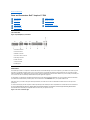
Dell™Inspiron™7500SystemReference
Information in this document is subject to change without notice.
©1999–2000 Dell Computer Corporation. All rights reserved.
Reproduction in any manner whatsoever without the written permission of Dell Computer Corporation is strictly forbidden. Trademarks used in this text: Dell, the DELL logo,
MegaBay, and Inspiron are trademarks of Dell Computer Corporation; Microsoft, Windows, MS-DOS, and WindowsNT are registered trademarks of Microsoft Corporation;
Intel and Pentium are registered trademarks, and Celeron is a trademark of Intel Corporation; Adobe is a trademark of Adobe Systems Incorporated, which may be registered
in certain jurisdictions.
Other trademarks and trade names may be used in this document to refer to either the entities claiming the marks and names or their products. Dell Computer Corporation
disclaims any proprietary interest in trademarks and trade names other than its own.
Initial release: 20 Sep 1999
Last revised: 17 Aug 2000
Conventions
Technical Overview
Using the Computer
Utilities and Drivers for Windows 98
Utilities and Drivers for Windows NT
Technical Specifications
Setup Program
System Codes and Messages
Passwords and Security
Ports and Connectors
Power Sources
Power Conservation
Removing and Replacing Parts
Documentation

Back to Contents Page
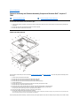
13.3-InchLCDBracketsandCarrierTrayRemoval:Dell™Inspiron™7500
This procedure assumes that you have removed the front bezel and the 13.3-inch LCD panel. To remove the brackets from the LCD panel, follow
these steps:
1. Detach the LCD wire harness from connector CN1 on the top left side of the inverter board.
2. Remove the (4) 6-mm screws from the sides of the mounting brackets.
3. Remove the brackets from the LCD panel.
To remove the 13.3-inch LCD panel from the carrier tray, follow these steps:
1. Remove any Kapton tape covering the CCFL cable.
2. Gently pull the cable out of its connector.
3. Remove any Kapton tape from the LCD wire harness.
4. Disconnect the LCD wire harness from the LCD panel.
5. Lift the LCD panel out of carrier tray.
Back to Contents Page
NOTICE: The metal on the carrier tray is sharp. Be careful not to cut yourself.

Back to Contents Page
13.3-InchLCDPanelRemoval:Dell™Inspiron™7500
This procedure assumes that you have removed the front bezel. Follow these steps to remove the 13.3-inch LCD panel:
1. Remove the (8) 6-mm screws that secure the left and right LCD brackets to the front plastic cover.
2. Detach the LCD wire harness from connector CN2 on the right side of inverter board.
3. If present, carefully remove the grounding tape between the inverter board and LCD panel.
4. Loosen the 3-mm screw securing the inverter board.
5. Lift the LCD panel, LCD brackets, and carrier tray, as a unit, out of the back cover.
Rotate upward from the bottom of the panel because the top slides underneath the plastic hooks.
6. Remove the hinges, which were previously held in place by pressure and screws.
To remove the inverter board, follow these steps:
1. Remove the 3-mm screw securing the inverter board to the back cover.
2. If you have not removed the LCD panel, disconnect the LCD wire harness from connectors CN1 and CN2 on the inverter board.
3. Remove the inverter board from the back cover.
Back to Contents Page

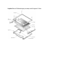
14.1-InchLCDPanel,Brackets,andCarrierTrayRemoval:Dell™Inspiron™7500
This procedure assumes that you have removed the front bezel. Follow these steps to remove the 14.1-inch LCD panel:
1. Remove the (8) 6-mm screws that secure the left and right LCD brackets to the front plastic cover.
2. Detach the CCFL cable from connector CN2 on the right side of inverter board.
3. Carefully remove the grounding tape between the inverter board and LCD panel.
4. Remove the 3-mm screw securing the inverter board, and unsnap the inverter board from the back cover.
5. Lift the LCD panel, LCD brackets, and inverter board as one unit out of the back cover.
Rotate upward from the bottom of the panel because the top slides underneath the plastic hooks.
6. Remove the hinges, which were previously held in place by pressure and screws.
To remove the LCD brackets from the LCD panel, follow these steps:
1. Remove the (4) 4-mm screws from the sides of the LCD brackets.
2. Remove the brackets from the LCD panel.
To remove the LCD panel from the carrier tray, follow these steps:
1. Lift the inverter board shield, pull it slightly away from the panel to expose the cabling, and detach the LCD wire harness from connector CN1 on the inverter
board.
2. Remove any Kapton tape covering the CCFL cable on the back of the LCD.
3. Gently pull the interposer board off the connector to the LCD panel.
4. Lift the LCD panel up and remove any tape between the LCD wire harness and the carrier tray.
5. Disconnect the LCD wire harness from the LCD panel.
6. Lift the LCD panel out of the carrier tray.
7. Disconnect the LCD wire harness from the LCD panel.
NOTICE: The metal on the carrier tray is sharp. Be careful not to cut yourself.

Back to Contents Page
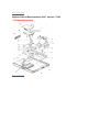
15-inchLCDPanelRemoval:Dell™Inspiron™7500
To remove the 15-inch LCD panel, perform the following steps:
1. Turn the computer over and remove the 4 screws from the bottom of the computer.
2. Turn the computer back over and open the display.
3. Remove the plastic hinge covers.
4. Insert a small flat-blade screwdriver or a similar plastic tool along the top-right edge of the keyboard, above the row of function keys. Working
from right to left, free the keyboard by prying it toward the front of the unit. When free, lift the top of the keyboard slightly to clear the palmrest
assembly.
5. Remove the keyboard bracket (located in the upper-right corner of the keyboard).
6. Remove the four screws that secure the two hinges.
7. Unplug the LCD wire harness and lift the assembly off the computer base.
To remove the front bezel, follow these steps:
1. Remove the two rubber screw covers and screws on the LCD near the hinge. Remove the remaining three plastic screw covers and screws,
one on either side and one in the front.
2. With all screws removed, unsnap the front bezel from the back cover and remove the bezel from the assembly.
To remove the LCD panel, hinges, and inverter board, follow these steps:
1. Remove the 4 remaining screw covers and screws on the sides of the LCD.
2. With all screws removed, lift the LCD panel out and disconnect the CCFL wire from the inverter board.
3. Detach the LCD wire harness from connector CN2 on the right side of the inverter board.
4. Carefully remove the grounding tape between the inverter board and the LCD panel.
5. Remove the two 2.5-mm screws securing the inverter board to the back cover.
6. Remove the inverter board from the back cover.
To reassemble, perform the steps in reverse order.
Back to Contents Page


Back to Contents Page
AudioDevices:Dell™Inspiron™7500
You can connect speakers, a microphone, headphones, and record/playback devices such as cassette players, CD players, and VCRs to the
audio connectors on the computer. The connectors are located directly under the PC Card slot. Dell recommends using amplified speakers for the
best sound.
Connect headphones or speakers to the headphone connector on the right of the audio connectors. Connect a microphone to the microphone-in
connector in the middle. Connect record/playback devices such as cassette players, CD players, and VCRs to the line-in connector on the left.
See your Microsoft
®
Windows
®
98 documentation for the location of sound application programs such as mixers and volume control.
You can control the sound coming from the external speakers and the computer's integrated speakers with the volume control dial. You can also
use the keyboard to adjust the volumes. Press to lower the volume. Press to increase the volume. Press to enable or
disable both the integrated and external speakers.
See Drivers for information about reinstalling the audio drivers. The drivers are located on the Dell Inspiron 7500 System Software CD.
Back to Contents Page
NOTE: If no sound comes from the speakers, make sure that the sound is not disabled. Press and check the volume
control dial.

Back to Contents Page
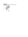
AudioCardandAudioThermalShieldRemoval:Dell™Inspiron™7500
****New artwork pending
This procedure assumes that you have removed the system board from the plastic case and have removed the PC Card cage from the system
board. To remove the audio card and audio thermal shield, follow these steps:
1. Gently pull the audio card off of connectors JP12 and JP13 on the system board. Do not rock the card to remove it, because this may
damage the connectors.
2. Remove the 10-mm screw securing the audio thermal shield, and then remove the shield.


Back to Contents Page
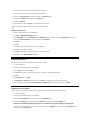
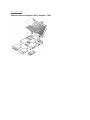
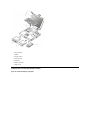
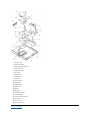
Base Assembly Component Removal:Dell™Inspiron™7500
Base Assembly
****New artwork pending
Base Assembly Component Removal
The following procedures assume that the keyboard, thermal shield, display assembly, and palmrest assembly have been removed.
Back to Contents Page
Base Assembly
Base Assembly Component Removal
PC Card Heat Sink Removal
Heat Exchanger/Fan Removal
DC-DC Board Removal
Processor Board and Memory Module Removal
Hinge Saddle Removal
RJ-11 Card Removal
System Board Removal
PC Card Cage Removal
Audio Card and Audio Thermal Shield Removal
Latch Assembly Removal


Back to Contents Page
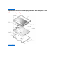
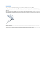
FrontBezelRemoval:Dell™Inspiron™7500
This procedure assumes that you have removed the display assembly from the computer base. To remove the front bezel, follow these steps:
1. Use a dental pick to pry the rubber screw covers off of the bottom 2 screws and the rubber bumpers off of the top 2 screws.
2. Remove the (4) 6-mm screws from the front bezel.
3. Unsnap the front bezel from the back cover and remove it from the assembly.
Carefully insert your fingers between the LCD panel and the bezel. Roll the plastic up slightly to insert your fingers further in, and then lift upward to free the snaps.
Start at the middle bottom and then work around.
When replacing the bezel, ensure that the LCD wire harness is routed correctly through the openings in the back cover and is not pinched.

Back to Contents Page
UsingtheComputer:Dell™Inspiron™7500
Storage Devices
Removing and Installing a Device in the Media Bay
The media bay holds a second battery, a combination CD-ROM drive/diskette drive, a combination DVD-ROM drive/diskette drive, a combination
DVD-ROM drive/LS-120 diskette drive, or an optional hard-disk drive.
To remove a device from the media bay, perform the following steps:
1. Save any open files.
2. Shut down the computer.
3. Remove the currently installed device from the media bay.
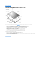
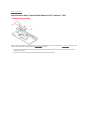
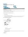
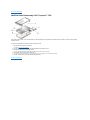
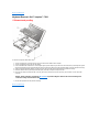
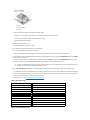
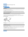
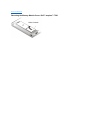
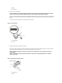
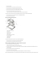
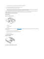
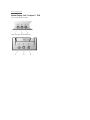
Close the display and turn the computer over. Push the latch lock to the unlocked position (see Figure 1), and slide the latch release in the
direction of the arrow. Keep holding the latch release with one hand while pulling the device out of the media bay with the other.
Figure 1. Removing Devices From the Media Bay
4. Install the new device in the media bay.
Insert the device into the media bay and push the latch lock back into the locked position. The label on the device will be facing away from
you when the computer is turned over.
5. Reboot the system.
Hard-Disk Drive
Storage Devices
Touch Pad
Audio Devices
PC Cards
Embedded Numeric Keypad
External Monitor
External Keyboard, Keypad, or Mouse
NOTE: All devices are removed and installed the same way.
1
Latch release
2
Combo module or secondary battery
3
Latch lock (unlocked position)

To install a hard-disk drive, perform the following steps.
1. Save any open files.
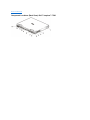
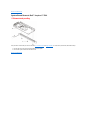
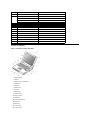
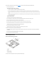
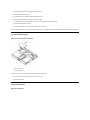
2. Shut down the computer and remove any installed batteries (see Figure 2).
Figure 2. Removing a Battery From the Media Bay
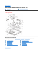
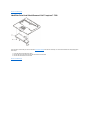
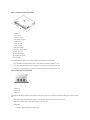
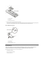
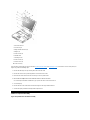
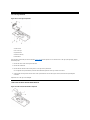
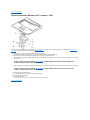
3. Remove the currently installed hard-disk drive (see Figure 3).
Turn the computer over, and loosen the two captive screws securing the hard-disk drive cover. The screws are held captive in the lip of the
carrier. A spring causes the front edge of the cover to pop up. If the front edge of the cover does not pop up, pull on one of the screws to lift
the front edge.
Figure 3. Removing the Hard-Disk Drive
4. Push the hard-disk drive forward until it stops, and then pull it up.
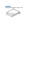
5. Remove the new drive from its packaging.
Save the original packaging to use when storing or shipping the hard-disk drive.
6. Slide the new drive into place.
NOTE: The computer's BIOS may not support hard-disk drives obtained from vendors other than Dell. Dell does not guarantee
compatibility or provide support for hard-disk drives obtained from other sources.
NOTICE: To prevent data loss, shut down your computer before removing or installing your hard-disk drive. Do not remove the
hard-disk drive if the computer is in suspend mode or save-to-disk mode or if the hard-disk drive access indicator is lit.
1
Latch lock (unlocked position)
2
Battery
3
Latch release
NOTICE: When the hard-disk drive is not in the computer, protect the drive from exposure to static electricity by storing it in
protective packaging.
1
Hard-disk drive
2
Hinge
3
Captive screws (2)
NOTICE: While sliding the drive in, do not force it into place.

There may be some resistance as the drive connects to its interface connector at the back of the bay.
7. Tighten the screws you loosened in step 3.
8. Test the drive by running the Hard-Disk Drives (Non-SCSI) test group in the Dell Diagnostics.
For information on running the diagnostics, see "Running the Dell Diagnostics" in Chapter 3 of the Dell Inspiron 7500 Reference and
Troubleshooting Guide.
Audio Devices
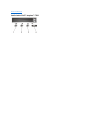
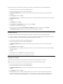
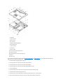
You can connect speakers, a microphone, headphones, and record/playback devices such as cassette players, CD players, and VCRs to the
audio connectors on the computer (see Figure 4). The connectors are located directly under the PC Card slot. Dell recommends using amplified
speakers for the best sound.
Figure 4. Audio connectors
Connect headphones or speakers to the line-out jack on the left of the audio connectors. Connect a microphone to the microphone jack in the
middle. Connect record/playback devices such as cassette players, CD players, and VCRs to the line-in jack on the right.
See your Microsoft®Windows®98 documentation for the location of sound application programs such as mixers and volume control.
You can control the sound coming from the external speakers and the computer's integrated speakers with the volume control dial. You can also
use the keyboard to adjust the volumes. Press to lower the volume. Press to increase the volume. Press to enable or
disable both the integrated and external speakers.
See Utilities and Drivers for Microsoft Windows 98 and Utilities and Drivers for Microsoft Windows NT® for information about reinstalling the audio
drivers. The drivers are located on the Dell Inspiron 7500 System Software CD.
Embedded Numeric Keypad
As you work, you may want to use the embedded numeric keypad (see Figure 5) to enter numbers into a spreadsheet or financial program. The
embedded numeric keypad shares some of the keys on the computer's keyboard. The embedded keypad numbers and symbols are marked on
the right of the keypad keys in blue.
Figure 5. Embedded Numeric Keypad
To activate the embedded numeric keypad, press <Num Lock>. The Number Lock indicator lights up.
1
Line-in jack
2
Microphone jack
3
Line-out jack
4
Volume control dial
NOTE: If no sound comes from the speakers, make sure that the sound is not disabled. Press and check the
volume control dial.

To deactivate the embedded keypad, press <Num Lock>. The Num Lock indicator is no longer illuminated.
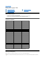
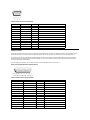
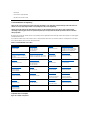
When the embedded keypad is activated, the key combinations in Table 1 temporarily disable specific keypad keys.
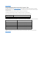
Table 1. Activated Keypad Functions
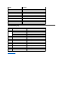
To use the embedded arrow keys, ensure that <Num Lock> is off. Press and hold <Fn> and the corresponding key displayed in Table 2.
Table 2. Deactivated Keypad Functions
External Keyboard, Keypad, or Mouse
You can connect a keyboard with a standard connector to the Personal System/2 (PS/2) connector on the computer by using an adapter available
from Dell. You can use the integrated keyboard even when an external keyboard is attached to the computer. You can also connect a Universal
Serial Bus (USB) keyboard to the computer's USB connector.
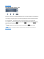
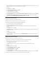
Attach a PS/2 mouse to the PS/2-compatible connector on the computer (see Figure 6) or a USB-compatible mouse to the USB connector. If you
attach a USB mouse to the computer, you do not need to reboot the computer in order to use the mouse. The touch pad device drivers that Dell
installed on your hard-disk drive work with a PS/2 mouse, serial mouse, or USB mouse from Dell.
Figure 6. Attaching a PS/2 Mouse
If you did not receive your mouse from Dell, you may need to install device drivers separately to use the mouse. This software is usually included
with mouse installation kits.
Touch Pad
The PS/2-compatible touch pad detects the position of your finger over a touch-sensitive area and provides the computer full mouse functionality.
The touch pad's two buttons correspond to the left and right buttons on a standard mouse.
When Keypad Is Activated
(Number Lock Indicator ON)
Function
<Fn><key>
Enables the lowercase letter or primary function of that specific key
<Fn><Shift><key>
Enables the uppercase letter or shift function of that specific key
When Keypad Is Deactivated
Function
<Fn><j>
Performs the same function as pressing <End>
<Fn><7>
Performs the same function as pressing <Home>
<Fn><k>
Performs the same function as pressing the down-arrow key
<Fn><8>
Performs the same function as pressing the up-arrow key
<Fn><u>
Performs the same function as pressing the left-arrow key
<Fn><o>
Performs the same function as pressing the right-arrow key
<Fn><.>
Performs the same function as pressing <Delete>
NOTE: The embedded numeric keypad is automatically disabled if an external keyboard or keypad is connected to the computer.
NOTE: If you are using a PS/2 mouse that is not Microsoft-compatible and the mouse does not work properly, reboot the computer. If
the mouse still does not work, install the drivers from the diskette that came with the mouse and reboot the computer.

To move the cursor, lightly slide your finger over the smooth sensor area. To select an object, gently tap once on the surface of the touch pad. To
select and move (or drag) an object, position the cursor on the object and tap down-up-down on the touch pad. On the second down motion, leave
your finger on the touch pad and move the selected object by sliding your finger across the surface. To double-click an object, position the cursor
on the object and then tap twice.
To customize touch pad and cursor features, perform the following steps:
1. Click the Start button, point to Settings, and then click Control Panel.
The Control Panel window appears.
2. Double-click the Mouse icon.
3. Select the Touch Pad tab.
4. Make your selections. Click the Help button if you need more information.
Dell has already installed the touch pad drivers for you.
Installing the Touch Pad/Mouse Driver
See Utilities and Drivers for Microsoft Windows 98 and Utilities and Drivers for Microsoft Windows NT for information about reinstalling touch
pad/mouse drivers.
PC Cards
The computer has two slots (see Figure 7) into which up to two 3.3- or 5-volt (V) PC Cards that comply with the Personal Computer Memory Card
International Association (PCMCIA) standard and Japanese Electronic Industry Development Association (JEIDA) Release 4.2 can be installed.
Both PC Card slots support CardBUS technology. In addition, a zoomed video (ZV) port is available from the lower slot (slot 0). If you ordered an
Moving Pictures Experts Group (MPEG)-2 decoder PC Card from Dell, install it in the lower PC slot for high-performance graphics.
Figure 7. PC Card Slots
The computer supports two Type I, two Type II, or one Type III PC Card, including such memory devices as static random-access memory (SRAM)
cards that emulate diskettes, RAM cards, one-time programmable (OTP) ROM cards, and Advanced Technology Attachment (ATA) cards that
emulate integrated drive electronics (IDE) hard-disk drives. Also supported are input/output (I/O) cards such as modem communication cards,
local area network (LAN) cards, wireless LAN cards, small computer system interface (SCSI) cards, and sound cards. You can also use extended
PC Cards in the computer.
Installing a PC Card
The PC Card slot has two PC Card connectors and can hold up to two cards in one of the following configurations:
l A single Type I or Type II card (using either the top or bottom PC Card connector)
NOTE: Keep your fingers away from the touch pad while the computer is booting or loading the operating system. If you touch the touch
pad at either time, the cursor will not move until you remove your finger from the touch pad surface.
1
Top eject button
2
PC card
NOTE: A PC Card is not a boot device.
NOTICE: Take extra precautions if you use extended PC Cards in the computer. Extended cards are longer versions of standard
PC Cards. They fit into, and operate correctly with, the computer. However, they extend beyond the edge of the computer when
installed. If something strikes the exposed end of an installed card, the card or the system board can be damaged.
NOTICE: Because of space considerations, you may have trouble using two PC Cards in the computer if one of them is an
extended card. Always install an extended card in the top PC Card connector. Always remove an extended PC Card before you
pack the computer for traveling.

l One Type I card and one Type II card (using either connector)
l Two Type I cards or two Type II cards
l A single Type III card (using the bottom connector)
The type of card refers to its thickness, not its functionality. Because a Type III card is thicker than Type I and Type II cards, it takes up the entire
PC Card slot, although it uses only one PC Card connector.
PC Cards are generally marked (with a triangle or an arrow) to indicate which end should be inserted into the slot. The cards are keyed to prevent
incorrect insertion. If card orientation is not clear, see the documentation that came with the card.
You can install a PC Card while the computer is running. The PC Card is automatically detected. To install a PC Card, hold the card with its
orientation symbol pointing into the slot and the top side of the card facing up. Insert the card into the slot, and press in firmly until the card is
completely seated in the internal PC Card connector. If there is too much resistance when inserting the card, do not force the card. Check the
card's orientation, and try again.
When a PC Card is being used, the PC Card access indicator appears in the status display panel. The computer recognizes most I/O cards and
automatically loads the appropriate device driver. If you have older modem communications software that cannot use interrupt request (IRQ)8 or
higher, you must disable the serial port or infrared port to use the software.
Removing a PC Card
To remove a PC card from the top connector, press the top eject button twice (identified by an arrow pointing up). To remove a PC card from the
bottom connector, press the bottom eject button twice (identified by an arrow pointing down). If you are removing a Type III card, press the bottom
eject button twice.
The first time you press an eject button, the eject button itself pops out. The second time you press the eject button, the PC Card is released and
extends slightly from the slot. Grasp the end of the card, and pull it completely from the slot.
See Utilities and Drivers for Microsoft Windows 98 and Utilities and Drivers for Microsoft Windows NT for information on installing utilities and
drivers.
Configuring a PC Card
If you are using the Microsoft Windows 98 operating system, click the Start button, point to Settings, and then click Control Panel. Double-click
the PC Card to open the PC Card Properties window. For more information, check the documentation that came with your operating system.
You can also double-click the PC Card icon on the Windows 98 desktop.
External Monitor
Use the 15-pin video connector to attach an external monitor to the computer. If you reconfigure your hardware, you may need pin number and
signal information for the monitor connector. To connect an external monitor, perform the following steps.
1. Turn off the external monitor.
Set the monitor on a monitor stand, desktop, or other level surface near the computer.
2. Connect the external monitor's video cable to the computer.
Plug the monitor cable connector into the matching video connector at the back of the computer. If the cable is not permanently attached to
the monitor, connect it to the monitor also. Tighten all the screws on the video cable connector(s) to eliminate radio frequency interference
(RFI).
3. Connect your external monitor to a grounded AC power source.
Plug the three-prong connector on one end of the monitor's power cable into a grounded power strip or some other grounded power source.
If the cable is not permanently attached to the monitor, connect it to the monitor also.
The video image can be displayed on an external monitor, on the computer's display, or on both simultaneously. To toggle between the three
display modes, press <Fn><F8>.
If the external monitor is turned off when you boot the computer, and if the Video Display Device category is set to CRT Mode in the Main menu
of the Setup program, the computer sends the video image to the external monitor. In this case, you do not see an image on either the computer's
display or on the external monitor. To resolve this situation, turn on the external monitor or press <Fn><F8> to switch the video image to the
computer's display.
Whether you are using an appropriately equipped multifrequency monitor only or an external monitor and the built-in display simultaneously, you
can display up to 256 colors at a noninterlaced resolution of 1400 x 1050 pixels at a 32-bit color depth.
NOTICE: Do not place the external monitor directly on top of your portable computer, even if it is closed. Doing so can
crack the computer case, the display, or both.
Page is loading ...
Page is loading ...
Page is loading ...
Page is loading ...
Page is loading ...
Page is loading ...
Page is loading ...
Page is loading ...
Page is loading ...
Page is loading ...
Page is loading ...
Page is loading ...
Page is loading ...
Page is loading ...
Page is loading ...
Page is loading ...
Page is loading ...
Page is loading ...
Page is loading ...
Page is loading ...
Page is loading ...
Page is loading ...
Page is loading ...
Page is loading ...
Page is loading ...
Page is loading ...
Page is loading ...
Page is loading ...
Page is loading ...
Page is loading ...
Page is loading ...
Page is loading ...
Page is loading ...
Page is loading ...
Page is loading ...
Page is loading ...
Page is loading ...
Page is loading ...
Page is loading ...
Page is loading ...
Page is loading ...
Page is loading ...
Page is loading ...
Page is loading ...
Page is loading ...
Page is loading ...
Page is loading ...
Page is loading ...
Page is loading ...
Page is loading ...
Page is loading ...
Page is loading ...
Page is loading ...
Page is loading ...
Page is loading ...
Page is loading ...
Page is loading ...
Page is loading ...
Page is loading ...
Page is loading ...
Page is loading ...
Page is loading ...
Page is loading ...
Page is loading ...
Page is loading ...
Page is loading ...
Page is loading ...
Page is loading ...
Page is loading ...
Page is loading ...
Page is loading ...
Page is loading ...
Page is loading ...
Page is loading ...
Page is loading ...
Page is loading ...
Page is loading ...
Page is loading ...
Page is loading ...
Page is loading ...
Page is loading ...
Page is loading ...
Page is loading ...
Page is loading ...
Page is loading ...
Page is loading ...
Page is loading ...
Page is loading ...
Page is loading ...
Page is loading ...
Page is loading ...
Page is loading ...
Page is loading ...
Page is loading ...
Page is loading ...
Page is loading ...
Page is loading ...
Page is loading ...
Page is loading ...
Page is loading ...
Page is loading ...
Page is loading ...
Page is loading ...
Page is loading ...
Page is loading ...
Page is loading ...
Page is loading ...
Page is loading ...
Page is loading ...
Page is loading ...
Page is loading ...
Page is loading ...
Page is loading ...
Page is loading ...
Page is loading ...
Page is loading ...
Page is loading ...
Page is loading ...
Page is loading ...
Page is loading ...
Page is loading ...
Page is loading ...
Page is loading ...
Page is loading ...
Page is loading ...
Page is loading ...
Page is loading ...
Page is loading ...
Page is loading ...
Page is loading ...
Page is loading ...
Page is loading ...
Page is loading ...
Page is loading ...
Page is loading ...
Page is loading ...
Page is loading ...
Page is loading ...
Page is loading ...
Page is loading ...
Page is loading ...
Page is loading ...
Page is loading ...
Page is loading ...
Page is loading ...
-
 1
1
-
 2
2
-
 3
3
-
 4
4
-
 5
5
-
 6
6
-
 7
7
-
 8
8
-
 9
9
-
 10
10
-
 11
11
-
 12
12
-
 13
13
-
 14
14
-
 15
15
-
 16
16
-
 17
17
-
 18
18
-
 19
19
-
 20
20
-
 21
21
-
 22
22
-
 23
23
-
 24
24
-
 25
25
-
 26
26
-
 27
27
-
 28
28
-
 29
29
-
 30
30
-
 31
31
-
 32
32
-
 33
33
-
 34
34
-
 35
35
-
 36
36
-
 37
37
-
 38
38
-
 39
39
-
 40
40
-
 41
41
-
 42
42
-
 43
43
-
 44
44
-
 45
45
-
 46
46
-
 47
47
-
 48
48
-
 49
49
-
 50
50
-
 51
51
-
 52
52
-
 53
53
-
 54
54
-
 55
55
-
 56
56
-
 57
57
-
 58
58
-
 59
59
-
 60
60
-
 61
61
-
 62
62
-
 63
63
-
 64
64
-
 65
65
-
 66
66
-
 67
67
-
 68
68
-
 69
69
-
 70
70
-
 71
71
-
 72
72
-
 73
73
-
 74
74
-
 75
75
-
 76
76
-
 77
77
-
 78
78
-
 79
79
-
 80
80
-
 81
81
-
 82
82
-
 83
83
-
 84
84
-
 85
85
-
 86
86
-
 87
87
-
 88
88
-
 89
89
-
 90
90
-
 91
91
-
 92
92
-
 93
93
-
 94
94
-
 95
95
-
 96
96
-
 97
97
-
 98
98
-
 99
99
-
 100
100
-
 101
101
-
 102
102
-
 103
103
-
 104
104
-
 105
105
-
 106
106
-
 107
107
-
 108
108
-
 109
109
-
 110
110
-
 111
111
-
 112
112
-
 113
113
-
 114
114
-
 115
115
-
 116
116
-
 117
117
-
 118
118
-
 119
119
-
 120
120
-
 121
121
-
 122
122
-
 123
123
-
 124
124
-
 125
125
-
 126
126
-
 127
127
-
 128
128
-
 129
129
-
 130
130
-
 131
131
-
 132
132
-
 133
133
-
 134
134
-
 135
135
-
 136
136
-
 137
137
-
 138
138
-
 139
139
-
 140
140
-
 141
141
-
 142
142
-
 143
143
-
 144
144
-
 145
145
-
 146
146
-
 147
147
-
 148
148
-
 149
149
-
 150
150
-
 151
151
-
 152
152
-
 153
153
-
 154
154
-
 155
155
-
 156
156
-
 157
157
-
 158
158
-
 159
159
-
 160
160
-
 161
161
-
 162
162
-
 163
163
-
 164
164
-
 165
165


Dell Inspiron 7500 (End of Life) Owner's manual
- Category
- Notebooks
- Type
- Owner's manual
- This manual is also suitable for
Ask a question and I''ll find the answer in the document
Finding information in a document is now easier with AI
Related papers
-
Dell 24YUM User manual
-
Dell 24YUM User manual
-
-
-
-
Dell Inspiron 3700 Quick start guide
-
Dell Inspiron 7000 Quick start guide
-
-
-
Other documents
-
Gleason Reel Mouse Pad Tray Assembly Instructions
-
Zebra NX-7510/NX-7520/NX-7530 Owner's manual
-
Clevo P170EM User manual
-
Samsung N860GU4004 User manual
-
-
Apple CD/DVD Drive User manual
-
D ADDARIO Varigrip Operating instructions
-
 Chint Power CPS SCE4 Operating instructions
-
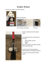 Mophorn Button Maker Operating instructions
-
BTC 2001ARF User manual

