THUNDER TIGER Raptor 30 V2 Assembly & Maintenance Manual
- Category
- Toys & accessories
- Type
- Assembly & Maintenance Manual


(3)
(4)
(1)
75mm
3
[1]The engine will not start.
* The engine starting shaft will not turn:
The engine may be flooded with too much fuel. Please remove the glow plug first, then turn the engine
with the electric starter until the excess fuel spits out of the glow plug hole.
* The engine turns when the electric starter is applied, but the engine will not start:
(1) Is the glow plug working? Remove the glow plug and does the platinum coil glow red when a 1.5
volt battery is applied to the plug? If not, then the glow plug battery may be weak and old.
(2) Is the carburetor needle properly set? Please refer to the engine instruction manual for the proper
needle setting.
(3) Does the throttle control arm move properly and in the correct direction according your transmitter
command?
* Engine will start, but quits immediately.
(1) Use the transmitter to increase the carburetor opening slightly. The throttle stick should never exceed
the 1/3 positiom when starting the engine.
(2) Try a new or different type of glow plug. There are different types of glow plugs on the market for
different types of fuel and operating conditions. Seek the advice of experienced fliers and also
experiment with di
fferent types of glow plugs until you find the one that suits your operating condition
the best.
*Engine runs, but the helicopter will not lift off.
(1) Check the main rotor blade pitch angle, they should be set at 5.5 to 6 degrees when the transmitter
throttle/collective stick is at the center position.
(2) Does the engine throttle arm move properly? The carburetor opening should be fully open when
the transmitter throttle/collective stick is moved up. The carburetor opening should be nearly closed
when the transmitter throttle/collective stick is moved down. And the opening should be completely
closed when the transmitter throttle/collective stick is moved down and the throttle trim is also
moved down.
(3) The carburetor needle is not set properly. Close the needle (turn it clockwise) all the way, then
open the needle (turn it counter clockwise) 1 and 1/2 turns and try again. If the model still will not
lift, then the engine maybe running too rich. If th
e symptom is the engine exhaust has a lot of
smoke and the engine coughs and wants to quit when the transmitter throttle/collective stick is
moved up, then close the needle 1/8 turn at a time, until the model will lift off. Do not turn the
needle too far inward, that will make the engine run too lean and over-heat and damage the engine.
[2] Helicopter problems.
* The helicopter shakes.
(1) Is the blade spindle bent?
(2) Is the flybar bent?
(3) Is the main rotor shaft bent?
(4) Are the two control paddles mounted at the same distance from the rotor shaft, and the paddles
are parallel to each other, and in the proper direction?
(5) Is the tail rotor shaft bent? The tail rotor blades mounted properly or damaged?
(6) Are the main rotor blades damaged or mounted in the proper orientation? The blades may require
additional balancing. The blade balance can be checked by removing both blades and then use
one of the 4mm blade bolt a
nd nut to hold the two blades together like a teeter totter. Then, hold
the blade bolt with your thumb and index finger. The two blades should teeter and remain in a
level position. If not, then add some tape to the lighter blade near the blade tip until the two blades
teeter in a level position. Hobby shops also sell blade balancers that are designed solely for
balancing model helicopter blades.
TOOLS REQUIRED FOR ASSEMBLY
OTHER ITEMS REQUIRED
7
4 Main Drive Gear Assembly
8
6 Main Frame Assembly-Part2
9
7 Main Frame Assembly-Part3
10
9 Engine Assembly
11
11 Main Rotor Head Assembly
12131516
17
18 19 21 22
FLIGHT TRAINING SECTION
23 24 25
28
26 27
29
30
MAINTENANCE SECTION
31
3233
Preflight Checklist and Starting Procedure
(1) Check to make sure there is no radio interfence before operating the model helicopter.
(2) Make sure the transmitter and receiver are on and all controls operate properly before flight.
Range check the radio.
(3) The engine carburetor must be in the idle position before starting the engine. Please read
the engine instruction manual on how to properly adjust the engine. Set the carburetor main
needle according to the engine instruction. Depending on the fuel and glow plug used, the
carburetor idle screw may require fine adjustment of 1/4 to 1/2 turn away from the factory
setting.
(4) Fill the fuel tank, move the throttle stick to idle, and connect the glow plug battery to the glow
plug.
(5) Use a 12 volt electric starter along with
a 6 mm hex starter extension (sold
seperately) to start the engine.
*Always grab on the
helicopter main rotor head
when starting the engine.
Otherwise, the main rotor
may start spinning
immediately after the
engine is started.
Flying Adjustments (1)
Tracking adjustment ... When the two main rotor blades are in track it means their blade tips
should follow the same path as they rotate.
(1) Rev up the motor until the helicopter becomes
light on its skids. Stand about 15 feet(4 meters)
alway from the helicopter.
(2) When the two main rotor blades are in
track it means the blade tips should follow
the same path as they rotate.
(3) When both blades are in track, the blade
tips will appear to overlap as seen from
the edge of the rotor plane.
If the blades are out of track, then adjust
one of the pushrods that connects to the
main rotor blade pitch arm.
Redo steps (1) to (3) until
the blades are tracking
properly.
In hover, the main blades should be
around 5.5 to 6 degrees in pitch.
Flying Adjustments (2)
Trimming: All helicopters are inherently unstable. But when a helicopter is properly trimmed, it
will not drift away or yaw by itself quickly. Use the following procedure to trim your
helicopter.
(1) If the helicopter nose starts to yaw left or right,
then
use the transmitter trim to compensate:
Hover Training (1)
Hovering is when the helicopter is floating in a stationary position in the air. Hovering is the
fundamental manuever to learn first. Here is the procedure to practice hovering:
(1) Make sure there are no spectators anywhere
near the model helicopter. You, the pilot,
should stand at least 10 meters (30 feet)
behind and slightly to the side of the model
helicopter.
(3) Increase the throttle/collective to lift the model helicopter skids off the
ground to no more than 10 cm(4 inches). Initially, it will be very difficult
to control the model to prevent it from moving. For a beginner it will
also be difficult to determine whether the helicopter is in trim or not.
But with repeated practice close to the ground you will develop a feel
for the controls. It is recommended to let a more experienced model
helicopter pilot trim out your new model before you attempt to learn
to hover.
Hover Training (2)
(1) It will take a few hours of hover practice with the helicopter skids at 10 to 20 cm (4-8 inches)
off the ground in order to comfortably control the model.
Do not try to lift the model to more than 10 to 20 cm(4-8 inches) in the beginning because
then the model may tip over readily when the beginner panics and an incorrect command is
given. Once you can keep the model in one place, then it is time to slowly increase the height
by a few centimeters (inches) each flight. Soon, you will be able to hover the helicopter
confidently a few feet high. Beginners should always practice hovering close to the ground
because in an emergency, throttle and collective can be reduced rapidly without causing a
large drop or damage to the model. If the model is hovering beyond one meter(3 feet) altitude,
always descend slowly. A panic drop can damage the helicopter.
(2) Always stand behind the model heli
copter when learning how to hover.Then you can watch
the nose of the helicopter. A left tail rotor command will yaw the helicopter nose to the left,
and a right command will yaw to the right. Similarly, a left cyclic command will cause the
helicopter to translate left. After you can comfortably hover the model at one meter high
without drifting, then start practice hovering while standing to either side of the model.
Eventually, you need to be comfortable at hovering
the model from any orientation, including with
the helicopter nose pointing at you. This is
challenging because control directions are
reversed.
(3) Once you can confidently hover a model helicopter at any altitude and at any orientation,
then congratulate yourself because y
ou have mastered 80% of the fundamental control
movements of a helicopter.
Forward Flight Training
After mastering hovering flight:
(1) Start practicing moving the helicopter laterally to the left or right slowly from a 1.5 meter (60
inches) high hover. This is the beginning exercise of translational flight.
(2) After a few hours of practicing step (1) and you are comfortable with translational movement,
start using some tail rotor control so the helicopter nose will point slightly to the left or right as
you fly it to the left or right. Eventually, this pattern will become a figure-eight in front of you.
Please visualize these movements in your mind.
After Flight Checklist
(1) Check every screw and bolt to make sure none has loosened due to vibration.
(2) Check every rotating and movable part to ensure they still move smoothly and
normally.
(3) Clean off the exhaust residue from the muffler, engine, and helicopter.
(4) Check all movable parts, such as gears, ball links, belt, etc. for unusual wear.
Trouble Shooting
(1) HMC3-12B Socket Screw (M3x12).......... 4
(2) HMQ14 Snap Ring....................................2
(3) BV0033 One Way Clutch Housing.............1
(4) BK0031 Main Spur Gear........................... 1
(5) BK0032 Tail Drive Pulley...........................1
(6) BK0034 One Way Clutch Shaft..................1
12 Main Frame Assembly-Part5
14 Tail Boom Assembly
16 Servo Installation-Part1
17 Servo Installation-Part2
Receiver
Transmitter
(helicopter type only
6 or more channels)
Servo x 5
Battery
1000mAh
Switch harness
Extended 6mm Hex
Starting Tool
Fuel Pump
HELI ENGINE(39-size)
34
Socket Drivers
Hex WrenchGrease
Blue Locktite
Instant Glue
Hobby Knife
Metric
4-way Wrench
ScissorsNipper5.5mm WrenchNeedle Nose PliersScrew Driver
Glow Plug Wrench
Gyro
Glow Fuel(15%-30%)
12V Battery
1.5V Glow starter
(1.2V~1.5V)
Rubber Band
Foam
RADIO SET
ENGINE
Glow Plug
12V Electric starter
7mm
5.5mm
7mm
8mm
5.5mm
7mm
8mm
10mm
*On the left side frame, there are
three pitch scales molded onto
the plastic frame. The three
different scales are designed for
beginner, intermediate or expert
F3C and 3D pilots.
*Use the "pointer" on the collective
tray and the plastic molded scales
to set up the initial collective
control.
*The actual blade angle in degrees
can be checked using a pitch
gauge (sold seperately).
Setting up Main Rotor Blades Pitch Angle
Changing tail rotor shaft:
1. Remove the tail rotor gear box from the tail boom.
2. Take apart the blade grips and remove or loosen the
M3x18 set screws.
3. Remove the tail rotor hub.
4. Pull out the tail rotor shaft.
5. Remove the plastic pulley by pushing out the 2mm
steel pin.
The hoveing pitch angle should be at 6˚. To get the 0˚ to 12˚
collective range, mount the steel linkage ball at 10.5mm away
from the center of the collective servo horn.
6˚ hovering pitch angle is used for beginners, intermediates and experts. The throttle/collective must be
in the center position when adjusting the collective pushrod length to make the "point" line up with the 6˚
hover point on the molded scale(see above diagrams).
For Beginners
For Intermediates
For F3C or 3D
Top End Pitch 12˚
Hover 6˚
Beginners 0˚
Intermediates -4˚
Bottem End Pitch -8˚
Pointer
Throttle Stick in the center
position
Move the throttle/collective stick to the full throttle position(see upper right diagram). The molded "pointer"
should now line up with the upper limit mark, which should provide about 12˚ of blade pitch.
*Move the throttle/collective stick to the low stick position. Use the ATV function of your transmitter to make
the "pointer" line up with the 0˚ mark for beginners(with the -4˚ mark for intermediates, and -8-degree
mark for experts).
Throttle at High Position
Throttle at Low Position
Collective Travel for F3C and 3D Flying
*To achieve +12˚ to -8˚ of collective travel range, the steel linkage ball must be moved to the inner
location as shown in the figure.
*Use ATV function of the transmittler to get the necesary servo travel.
The molded "pointer" should line up with the upper limit mark, which
should provide about 12˚ of blade pitch.
For intermediates set the low end to -4˚. For advanced F3C and 3D flying,
set the low end to -8˚.
Mount the steel linkage ball to the outer hole on the metal throttle arm. At full throttle stick, the
carburetor hole should open completely. At low throttle and with the throttle trim all the way down,
the carburetor
hole should close completely. Adjust the ATV function in your transmitter to achieve
the above requirement. Listen to the servo, it should not make any binding noise. Try keep the
throttle ATV between 90% and 110%. If your radio does not have ATV, then adjust the location
of the steel link ball on the throttle servo horn to get the correct throttle travel.
Engine Throttle Control Linkage
Preflight Adjustments
Relationship between the control motion and radio transmitter.
Always check all the controls to make sure they move
in the correct direction and there is no mechanical
binding or noise from the servos.
out of track
in track
increase
throttle gently
and not too
much
(3) If the helicopter noses down or up, then:
yaw right
yaw left
(A) situation: move to (b)
(B) situation: move to (a)
(2) If the helicopter rolls to left or right, then:
rolls right
rolls left
(C) situation: move to (d)
(d) situation: move to (c)
Noses down
Noses up
(E) situation: move to (f)
(F) situation: move to (e)
(2) Prior to lifting off, while the main rotor is spinning and the helicopter is
on the ground, check the main rotor fore/aft and left/right cyclic to make
sure the main rotor is tilting in the correct direction according to your
cyclic command. Move the tail rotor control stick to make sure the
helicopter nose will swing in the desired direction.
hovering at 1-1.5 meter
In the event the model has crashed.
(1)
(2)
(3)
(1)
(2)
(3)
(4)
Inspect the flybar, rotor shaft and the blade spindle to make sure they are not bent at all. If any item is
damaged, it must be replaced with a new part to ensure safe operation. Do not glue any broken or damaged
plastic part. Do not repair broken rotor blades. Always inspect the following items immediately:
Engine starting shaft.
All the gears.
Main shaft, flybar and blade spindle.
Tail boom and support.
Vertical and horizontal fins.
Tail rotor shaft and control system.
Main and tail rotor blades.
Changing the blade feathering spindle:
(1) Disconnect the linkage rods to the blade grips.
(2) Remove the 4mmx8 bolt.
(3) Pull out the blade grips gently.
(3)
(1)
(2)
Changing the tail drive belt:
(1)Loosen and remove all the necessary
screws.
(2)After installing the new belt, make sure
the belt is rotated 90˚ counter clockwise.
(1)
(1)
(1)
(1)
(1)
(2)
Changing the flybar:
(1) Loosen or remove the M3x10 set screws.
(2) Unscrew the control paddles.
* Make sure the distance from the rotor shaft to
both paddles are the same.
* If the flybar is not perfectly straight or
smooth, it can be lightly sanded.
(2)
(1)
* After reinstalling the flybar and paddles, make
sure the paddles are level and flat.
Remote Glow Plug
Extension
Epoxy
Mount the Steel
Linkage Ball at
10.5mm from the
center of the servo
horn.
FUTABA
Throttle at High Position
Throttle at Low Position
*High End Blade Pitch Setting
*Low End Blade Pitch Setting
*High End Blade Pitch Setting
*Low End Blade Pitch Setting
(Hint for beginners)
Linkage Position for F3C or 3D
Position for F3C or 3D
Make sure Linkage Balls are attached to the
inside hole of each stabilizer control lever.
Add a drop of CA to the two screws at the pivoting point of the collective pitch control arm.
Attach the linkage rod to the parallel elevator linkage balls.
(1) HSE3-18B
(2) HSE3-12B
(3) HMJ3-22B
(4) HMJ2-14N
(5) HMJ2-10N
(6) HMV1280
(7) HMV740ZZ
(8) HMV840ZZ
(9) BK0076
(10) BK0078
(1) HSE3-18B
(12) BK0084
(13) BK0075
(14) BK0023
(15) BK0018
(16) BK0020
(17) BK0022
(18) BK0019
(20) BK0093
(21) BK0021
(22) BK0017
(14) BK0023
(7) HMV740ZZ
(5) HMJ2-10N
(13) BK0075
(8) HMV840ZZ
(10) BK0078
(11) BK0088
(7) HMV740ZZ
(13) BK0075
(7) HMV740ZZ
(9) BK0076
(6) HMV1280
(13) BK0075
(1) HSE3-18B
(5) HMJ2-10N
(7) HMV740ZZ
(5) HMJ2-10N
(13) BK0075
(7) HMV740ZZ
(9) BK0076
(1) HSE3-18B
(19) BK0086
For sport kit (29BB) version,
(7) will be replaced by Bushing(BK0107x6)
(8) will be replaced by Bushing(BK0108x2)
Warning, do not over-torque the self-tapping screws.
58mm
Insert Main Shaft through the shaft bearings making sure that the end with the holes closest to the end is
pointed down. Next, slide main gear assembly into position on the shaft and line up the holes in the main
shaft with the holes in one way clutch shaft of the main gear assembly. Insert the socket head screw and
secure with the lock nut. Next, slide on the mainshaft lock ring on top of the main shaft bearing and secure
with the two set screws. Then slide on the swash plate assembly and attach the elevator and aileron
control linkages to the outside swash plate linkage balls. Next, slide on washout assembly and attach
washout linkage to the inner linkage balls of the swash plate.
Note: A piston lock purchased from your dealer will make this a
much easier task. You must replace the standard throttle arm
w/t
he extended throttle arm and attach the linkage ball.
Add blue Loctite to all metal to metal screw surfaces.
After installing the engine, connect the silicone fuel tube
to the carburator and muffler.
Assembly Hint: Start from the bottom of the main Rotor Hub and work your way up to the flybar assembly . When
screwing on the flybar paddles to the flybar, stop when you can see the rod in the window of the paddle. Then, lay
the assembly on a flat surface and align the paddles so they are exactly parallel. Insert and tighten the set screws.
Attach the flybar control rod to the flybar control arm and use the Double Link to connect the mixing lever (short
side) to the Main rotor Pitch Housing.
Slide the main Rotor assembly over the main shaft and align the two pins to
slide in the washout assembly. Make sure the holes in the main shaft line
up with the holes in the main rotor head. Insert the socket screw and secure
with locknut. Attach the ball linkage rods to the long end of the mixing lever
and to the remaining inside linkage balls of the swash plate.
Assembly Tip: Work from left to right when assembling the parts
. The tail pitch
control lever screws into the arm extending from the tail unit housing.
Assembly Tip: Slide the 3 rod guides onto the boom and space them out evenly as shown. Then slide the tail linkage
rod into the rod guides. Next, insert the tail rotor drive belt into the boom so that it comes out of both ends. Place
drive belt over tail drive pulley and complete balance of tail boom assembly. Remember to connect the tail linkage
rod to the tail control lever.
15 Main Frame Assembly-Part6
Pull the belt through the tail base, keeping the belt correctly aligned.
Push the tail boom into the tail base all the way to the end. Place the
drive belt over the tail drive spur gear. Then, gently pull back on the tail
boom until the tension on the belt allows no more than 5mm(3/16") of
free play in the belt. Tighten the locknuts and proceed with the rest of
the assembly.
Insert the four 3x20 socket screws into the tail base of the Main Frame
and secure with lock nuts. Do not tighten at this point.
Hold the tail boom in one hand and hook your index finger on your free
hand through the exposed loop of the tail rotor drive belt. Hold it so the
belt is vertical and parallel to the tail drive pulley.
Boom Drive belt
Important: Next, rotate the belt 90-degree counter clockwise.
90-degree
Assembly Tip: Remove all the servo wheels prior to attaching the steel linkage
balls. Make sure all linkages are the correct length.
Before installing Aileron Servo, tape the
wire as shown.
86mm
73mm
Mount the Steel Linkage Balls at 10.5mm
(approx 7/16") from the center of the servo
horn.
FUTABA
(1) HSE2612N Self Tapping Screw(M2.6x12)....12
(2) HMF2-8N Screw(M2x8).................................4
(3) HML2 Hex Nut(M2).......................................4
(4) HME4-5B Set Screw(M4x5)..........................2
(5) BK0093 Linkage Rod....................................2
(6) BK0094 Linkage Rod.....................................1
(7) BK0100-1 Linkage Rod.................................1
(8) BK0105 Tail Control Rod Joint.......................1
(9) BK0075 Linkage Ball.....................................4
(10) BK0086 Ball Link.........................................7
Mount the Steel Link
Ball at 10.5mm(approx
7/16") from the center
of the servo horn.
51mm
(1) HSE2612N Self Tapping Screw(M2.6x12)....8
(2) HMF2-8N Screw(M2x8)................................3
(3) HML2 Hex Nut(M2)......................................3
(4) BK0075 Linkage Ball....................................3
(5) BK0094 Linkage Rod ..................................1
(6) BK0092 Linkage Rod ..................................1
(7) BK0086 Ball Link..........................................4
Assembly Tip: Remove all the servo wheels prior to attaching the steel linkage
balls. Make sure all linkages are the correct length.
Linkage Position for beginner
Training Gear
(for beginners only)
Ball Link Pliers
(1) HMC3-10B
(4) No.9604
(3) BV0038
(1) HMC3-10B
Tighten the engine nut securely by
grabbing the plastic fan with a towel.
Add Blue Locktite
Linkage Ball to
throttle Arm
with a liability insurance plan as well as monthly magazine entitled Model Aviation. All
AMA charter aircraft clubs require all pilots to hold a current AMA sporting license prior
to operation of their models at club fields. For further information, contact the AMA at:
Academy of Model Aeronautics
5151 East Memorial Drive
Muncie, IN 47302
(317) 287-1256
1. Make sure both the transmitter and receiver batteries are fully charged prior to operation the
helicopter.
2. Make sure all flight controls operate properly prior to flying.
3. Range check the radio before the first flight. The servos must operate properly with the
transmitter antenna collapsed at a range of at least 50 ft.(15 meters).
4. Check to make sure there is no radio interference on your radio channel before operating
the helicopter.
5. Use only the recommended engine fuel as specified by the engine manufacturer.
6. Make sure the transmitter and receiver are turned on before starting the engine.
7. The engine throttle must be in the idle position before starting the engine.
8. Model helicopter main and tail rotors operate at high RPM. Make sure nothing can come in
contact with the rotor blades during flight.
9. After starting the helicopter, maintain a safe distance during the flight.
10. N
ever operate the helicopter in rain or excessive wind conditions.
11. Always operate and fly your helicopter in a safe and responsible manner.
12. Never fly a model helicopter over other pilots, spectators or cars.
POST FLIGHT INSPECTION
1. Inspect the model thoroughly to insure no parts have come loose or become damaged during
the flight and landing. Replace damaged parts and tighten loose screws before flying again.
2. Pump out any remaining fuel from the fuel tank.
3. Wipe off excess oil and fuel from helicopter body and other exposed parts.
4. Lubricate all moving parts ensure smooth operation for the next time you fly.
5. Store model in a cool, dry place. Avoid storage in direct sunlight or near a source of heat.
Following these few, simple safety rules will allow you to enjoy the thrill of model helicopter flying
for many years to come.
FLIGHT SAFETY CHECKLIST
2
(2) BV0589
66mm
(4) BK0095
(5) BK0170
(7) BA1578
(4) BK0095
(26) BK0024
100mm
(21) BK0027
14
Blade Modification
1.Mark around blade grips with a felt-tip marker.
2.Remove blade grips and cut covering lightly .125”
inside of mark,being careful not to cut into the blade.
3.Repeat for opposite side.
4.Trim bosses if necessary to allow tight fit to the blades.
5.Lightly sand inside of grips for better adhesion.
Apply Epoxy to blades in area shown top and bottom.
6.Attach blade grips and tighten screws.
7. Wipe off the excess Epoxy.
Idea and original art submitted by Randy Wishon,
Progressive Technologies, inc.
Dear Raptor Customers:
The stock wood blades should be operated with a main rotorspeed of no more than 1700 RPM. If the blades
are going to be operated at more than 1700 RPM, such as for aerobatics, then it is recommended reinforcing
the blade root section with epoxy. The enclosed drawing illustrate how to remove the plastic blade grips and
then carefully slice away some of the covering material, and add the "thin" type CA glue to further strengthen
the wood. After installing the plastic blade grips, apply epoxy around the seem of the plastic grip and the wood
to seal it off. This adds more strength and prevent oil from seeping through. For beginners, the best rotorspeed
is around 1550 RPM. For advanced fliers, a good hovering RPM is around 1550, and a constant 1800RPM in
idle-up for 3D aerobatics.
35
1
INTRODUCTION
CONTENTS
WARNING
This radio controlled helicopter is not a toy. It is a sophisticated piece of equipment and
is designed for hobby use only. If not properly assembled and operated, it is capable of
causing property damage and bodily harm to both the operator and/or spectators. Thunder
Tiger and its duly authorized distributors assume no liability for damage that could occur
from the assembly and/or use/misuse of this product.
AMA INFORMATION
Operating a model helicopter requires a high degree of diligence and skill. If you are a
newcomer to the hobby, it is best to seek help and guidance from accomplished model
helicopter pilots. This will greatly speed up the learning process and have you flying
successfully in a reasonable time. We also would strongly urge you to join the Academy
of Model Aeronautics. The AMA is a non-profit organization that provides its members
Congratulations on your purchase of the Raptor 30 V2 helicopter. This model was designed and
engineered by the World-renowned Mr. Shigetada Taya. It combines elements of his previously
successful designs with today's advanced technologies. Since the introduction of the original
Raptor 30 in 1998, many have been sold around the world. It is the most popular 30-size helicopter
in the world. The Raptor 30 has helped beginners master th
e art of RC helicopter flying. The
Raptor 30 has helped experienced pilots learn new 3-D maneuvers. This is truly a versatile model
helicopter for everyone. We did not just sat on our laurel, our team of engineers and test pilots
have collected feedbacks from around the world and have now made the Raptor 30 an even better
helicopter. We made new molds and tooling for new parts. Many area have subtle changes to
increase strength and durability.
As one of the largest R/C manufacturers in the world, Thunder Tiger has spared no expense to
bring you this incredible new machine. All production parts are manufactured by use of the most
modern technology available and meets or exceeds the standards as set forth by ISO-9001.
In the last few years we have spend time and resource to develop a new Thunder Tiger PRO-
39H(R) ring engine for the Raptor 30 V2 and for other 30-size helicopters. The new PRO-39
H(R)
has much better transition characteristics than the Pro 36H ABC engine. The needles are easy
to set. The ring design eliminates the criticalness of ABC engines. You will find the new 39H
engine produce more power than any other available 30-size engines. Together, the new Raptor
30 V2 and the PRO 39H(R) engine will provide you with many hours of enjoyment. Thank you
again for purchasing our fine products.
Introduction.........................................p.1
Contents..............................................p.1
Warnings.............................................p.1
Additional Items Needed.....................p.3
Tools Needed......................................p.3
Assembling Section............................ p.4
Flight Training Section........................ p.22
Maintenance Section.......................... p.30
Blade Modification............................. p.35
4
ASSEMBLING SECTION
The parts in the Raptor kit are packed according to the assembly steps. The part number and quantity contained
in each are always shown in the square box on each page. Do not open all the bags at once. Open only the
bag that is needed for the current assembly step.
6
3 Main Frame Assembly-Part1
(1) HSE3-12B Self Tapping Screw (M3x12).. 30
(2) HMV696Z Bearing (d6xD15xW5).......... 1
(3) HMV6800 Bearing (d10xD19xW5).......... 2
(4) BK0059 Frame Spacer (S)....................... 8
(5) BK0058 Frame Spacer (L)...................... 4
(6) HME4-5B Set Screw (M4x5)................... 2
(7) BK0081 Pin............................................. 2
(8) BK0057 Servo Frame.............................. 1
(9) BK0599 Main Frame Left Side.............. 1
(10) BK0600 Main Frame Right Side..........1
(11) BV0035 Guide Pulley.......................... 2
(12) BK0036 Pulley Collar.......................... 4
(13) BK0592 Starter Shaft..........................1
(14) BK0594 Starter Coupling.................... 1
(15) Fuel Tank Assembly
(16) Clutch Assembly
(17) HMS5 E-CLIP..................................... 1
(18) BK0584 Thrust Washer.......................1
Please insert the frame spacers, bearings, pulley and parts in the frames according the drawing below. Tighten the
screws snugly, but do not over torque them which could strip the plastic.
Insert starter shaft through the center of the clutch bell assembly, through the top starter shaft bearing and into the
starter coupling. Secure with the two set screws. Make sure this is tightly secured.
(17) HMS5
The above pushrod lengths will permit 3D with the Raptor.
Use these lengths as a starting point. Beginners can also use those pushrod lengths, but just connect the
collective control to the outside point on the pitch control arm. Pushrod lengths are measured from ball link
center to ball link center.
Suggested throttle and collective pitch set up: Idle-up1 is used for continuous 3-D flips and aerobatics.
Idle-up2 is used for switchless inverted hover. Use a pitch gauge to check blade angles. It is easier to start
setting up idle-up2 blade pitch angles first. Beginners should inhibit idle-up1, idle-up2 and throttle hold.
Beginners should only use the Normal mode values. The model should hover at around 1550 rpm in Normal
mode, and flies at 1800 in idle-up1. Rotorspeed can be checked using TTR2000 MTF-301 helicopter
tachometer.
CONFIGURING THE RAPTOR FOR 3D
20
(18) BK0584
Changing the main rotor shaft:
(1) Disconnect the control rods to the washout arms.
(2) Disconnect the washout link to the swashplate.
(3) Loosen the set screws on the collar.
(4) Remove the 3mm x 20 bolt.
(5) Hold on to the plastic main gear and pull the 10mm
main rotor shaft upward.
Warning:
Please note the assembling
direction of the angular bearing.
If they are not assembled properly
as illustrated, they will easily fail
and result in unexpected danger.

(3)
(4)
(1)
75mm
3
[1]The engine will not start.
* The engine starting shaft will not turn:
The engine may be flooded with too much fuel. Please remove the glow plug first, then turn the engine
with the electric starter until the excess fuel spits out of the glow plug hole.
* The engine turns when the electric starter is applied, but the engine will not start:
(1) Is the glow plug working? Remove the glow plug and does the platinum coil glow red when a 1.5
volt battery is applied to the plug? If not, then the glow plug battery may be weak and old.
(2) Is the carburetor needle properly set? Please refer to the engine instruction manual for the proper
needle setting.
(3) Does the throttle control arm move properly and in the correct direction according your transmitter
command?
* Engine will start, but quits immediately.
(1) Use the transmitter to increase the carburetor opening slightly. The throttle stick should never exceed
the 1/3 positiom when starting the engine.
(2) Try a new or different type of glow plug. There are different types of glow plugs on the market for
different types of fuel and operating conditions. Seek the advice of experienced fliers and also
experiment with di
fferent types of glow plugs until you find the one that suits your operating condition
the best.
*Engine runs, but the helicopter will not lift off.
(1) Check the main rotor blade pitch angle, they should be set at 5.5 to 6 degrees when the transmitter
throttle/collective stick is at the center position.
(2) Does the engine throttle arm move properly? The carburetor opening should be fully open when
the transmitter throttle/collective stick is moved up. The carburetor opening should be nearly closed
when the transmitter throttle/collective stick is moved down. And the opening should be completely
closed when the transmitter throttle/collective stick is moved down and the throttle trim is also
moved down.
(3) The carburetor needle is not set properly. Close the needle (turn it clockwise) all the way, then
open the needle (turn it counter clockwise) 1 and 1/2 turns and try again. If the model still will not
lift, then the engine maybe running too rich. If th
e symptom is the engine exhaust has a lot of
smoke and the engine coughs and wants to quit when the transmitter throttle/collective stick is
moved up, then close the needle 1/8 turn at a time, until the model will lift off. Do not turn the
needle too far inward, that will make the engine run too lean and over-heat and damage the engine.
[2] Helicopter problems.
* The helicopter shakes.
(1) Is the blade spindle bent?
(2) Is the flybar bent?
(3) Is the main rotor shaft bent?
(4) Are the two control paddles mounted at the same distance from the rotor shaft, and the paddles
are parallel to each other, and in the proper direction?
(5) Is the tail rotor shaft bent? The tail rotor blades mounted properly or damaged?
(6) Are the main rotor blades damaged or mounted in the proper orientation? The blades may require
additional balancing. The blade balance can be checked by removing both blades and then use
one of the 4mm blade bolt a
nd nut to hold the two blades together like a teeter totter. Then, hold
the blade bolt with your thumb and index finger. The two blades should teeter and remain in a
level position. If not, then add some tape to the lighter blade near the blade tip until the two blades
teeter in a level position. Hobby shops also sell blade balancers that are designed solely for
balancing model helicopter blades.
TOOLS REQUIRED FOR ASSEMBLY
OTHER ITEMS REQUIRED
7
4 Main Drive Gear Assembly
8
6 Main Frame Assembly-Part2
9
7 Main Frame Assembly-Part3
10
9 Engine Assembly
11
11 Main Rotor Head Assembly
12131516
17
18 19 21 22
FLIGHT TRAINING SECTION
23 24 25
28
26 27
29
30
MAINTENANCE SECTION
31
3233
Preflight Checklist and Starting Procedure
(1) Check to make sure there is no radio interfence before operating the model helicopter.
(2) Make sure the transmitter and receiver are on and all controls operate properly before flight.
Range check the radio.
(3) The engine carburetor must be in the idle position before starting the engine. Please read
the engine instruction manual on how to properly adjust the engine. Set the carburetor main
needle according to the engine instruction. Depending on the fuel and glow plug used, the
carburetor idle screw may require fine adjustment of 1/4 to 1/2 turn away from the factory
setting.
(4) Fill the fuel tank, move the throttle stick to idle, and connect the glow plug battery to the glow
plug.
(5) Use a 12 volt electric starter along with
a 6 mm hex starter extension (sold
seperately) to start the engine.
*Always grab on the
helicopter main rotor head
when starting the engine.
Otherwise, the main rotor
may start spinning
immediately after the
engine is started.
Flying Adjustments (1)
Tracking adjustment ... When the two main rotor blades are in track it means their blade tips
should follow the same path as they rotate.
(1) Rev up the motor until the helicopter becomes
light on its skids. Stand about 15 feet(4 meters)
alway from the helicopter.
(2) When the two main rotor blades are in
track it means the blade tips should follow
the same path as they rotate.
(3) When both blades are in track, the blade
tips will appear to overlap as seen from
the edge of the rotor plane.
If the blades are out of track, then adjust
one of the pushrods that connects to the
main rotor blade pitch arm.
Redo steps (1) to (3) until
the blades are tracking
properly.
In hover, the main blades should be
around 5.5 to 6 degrees in pitch.
Flying Adjustments (2)
Trimming: All helicopters are inherently unstable. But when a helicopter is properly trimmed, it
will not drift away or yaw by itself quickly. Use the following procedure to trim your
helicopter.
(1) If the helicopter nose starts to yaw left or right,
then
use the transmitter trim to compensate:
Hover Training (1)
Hovering is when the helicopter is floating in a stationary position in the air. Hovering is the
fundamental manuever to learn first. Here is the procedure to practice hovering:
(1) Make sure there are no spectators anywhere
near the model helicopter. You, the pilot,
should stand at least 10 meters (30 feet)
behind and slightly to the side of the model
helicopter.
(3) Increase the throttle/collective to lift the model helicopter skids off the
ground to no more than 10 cm(4 inches). Initially, it will be very difficult
to control the model to prevent it from moving. For a beginner it will
also be difficult to determine whether the helicopter is in trim or not.
But with repeated practice close to the ground you will develop a feel
for the controls. It is recommended to let a more experienced model
helicopter pilot trim out your new model before you attempt to learn
to hover.
Hover Training (2)
(1) It will take a few hours of hover practice with the helicopter skids at 10 to 20 cm (4-8 inches)
off the ground in order to comfortably control the model.
Do not try to lift the model to more than 10 to 20 cm(4-8 inches) in the beginning because
then the model may tip over readily when the beginner panics and an incorrect command is
given. Once you can keep the model in one place, then it is time to slowly increase the height
by a few centimeters (inches) each flight. Soon, you will be able to hover the helicopter
confidently a few feet high. Beginners should always practice hovering close to the ground
because in an emergency, throttle and collective can be reduced rapidly without causing a
large drop or damage to the model. If the model is hovering beyond one meter(3 feet) altitude,
always descend slowly. A panic drop can damage the helicopter.
(2) Always stand behind the model helicopter when learning how to hover.Then you can watch
the nose of the helic
opter. A left tail rotor command will yaw the helicopter nose to the left,
and a right command will yaw to the right. Similarly, a left cyclic command will cause the
helicopter to translate left. After you can comfortably hover the model at one meter high
without drifting, then start practice hovering while standing to either side of the model.
Eventually, you need to be comfortable at hovering
the model from any orientation, including with
the helicopter nose pointing at you. This is
challenging because control directions are
reversed.
(3) Once you can confidently hover a model helicopter at any altitude and at any orientation,
then congratulate yourself because you have mastered 80% of the fundamental cont
rol
movements of a helicopter.
Forward Flight Training
After mastering hovering flight:
(1) Start practicing moving the helicopter laterally to the left or right slowly from a 1.5 meter (60
inches) high hover. This is the beginning exercise of translational flight.
(2) After a few hours of practicing step (1) and you are comfortable with translational movement,
start using some tail rotor control so the helicopter nose will point slightly to the left or right as
you fly it to the left or right. Eventually, this pattern will become a figure-eight in front of you.
Please visualize these movements in your mind.
After Flight Checklist
(1) Check every screw and bolt to make sure none has loosened due to vibration.
(2) Check every rotating and movable part to ensure they still move smoothly and
normally.
(3) Clean off the exhaust residue from the muffler, engine, and helicopter.
(4) Check all movable parts, such as gears, ball links, belt, etc. for unusual wear.
Trouble Shooting
(1) HMC3-12B Socket Screw (M3x12).......... 4
(2) HMQ14 Snap Ring....................................2
(3) BV0033 One Way Clutch Housing.............1
(4) BK0031 Main Spur Gear........................... 1
(5) BK0032 Tail Drive Pulley........................... 1
(6) BK0034 One Way Clutch Shaft..................1
12 Main Frame Assembly-Part5
14 Tail Boom Assembly
16 Servo Installation-Part1
17 Servo Installation-Part2
Receiver
Transmitter
(helicopter type only
6 or more channels)
Servo x 5
Battery
1000mAh
Switch harness
Extended 6mm Hex
Starting Tool
Fuel Pump
HELI ENGINE(39-size)
34
Socket Drivers
Hex WrenchGrease
Blue Locktite
Instant Glue
Hobby Knife
Metric
4-way Wrench
ScissorsNipper5.5mm WrenchNeedle Nose PliersScrew Driver
Glow Plug Wrench
Gyro
Glow Fuel(15%-30%)
12V Battery
1.5V Glow starter
(1.2V~1.5V)
Rubber Band
Foam
RADIO SET
ENGINE
Glow Plug
12V Electric starter
7mm
5.5mm
7mm
8mm
5.5mm
7mm
8mm
10mm
*On the left side frame, there are
three pitch scales molded onto
the plastic frame. The three
different scales are designed for
beginner, intermediate or expert
F3C and 3D pilots.
*Use the "pointer" on the collective
tray and the plastic molded scales
to set up the initial collective
control.
*The actual blade angle in degrees
can be checked using a pitch
gauge (sold seperately).
Setting up Main Rotor Blades Pitch Angle
Changing tail rotor shaft:
1. Remove the tail rotor gear box from the tail boom.
2. Take apart the blade grips and remove or loosen the
M3x18 set screws.
3. Remove the tail rotor hub.
4. Pull out the tail rotor shaft.
5. Remove the plastic pulley by pushing out the 2mm
steel pin.
The hoveing pitch angle should be at 6˚. To get the 0˚ to 12˚
collective range, mount the steel linkage ball at 10.5mm away
from the center of the collective servo horn.
6˚ hovering pitch angle is used for beginners, intermediates and experts. The throttle/collective must be
in the center position when adjusting the collective pushrod length to make the "point" line up with the 6˚
hover point on the molded scale(see above diagrams).
For Beginners
For Intermediates
For F3C or 3D
Top End Pitch 12˚
Hover 6˚
Beginners 0˚
Intermediates -4˚
Bottem End Pitch -8˚
Pointer
Throttle Stick in the center
position
Move the throttle/collective stick to the full throttle position(see upper right diagram). The molded "pointer"
should now line up with the upper limit mark, which should provide about 12˚ of blade pitch.
*Move the throttle/collective stick to the low stick position. Use the ATV function of your transmitter to make
the "pointer" line up with the 0˚ mark for beginners(with the -4˚ mark for intermediates, and -8-degree
mark for experts).
Throttle at High Position
Throttle at Low Position
Collective Travel for F3C and 3D Flying
*To achieve +12˚ to -8˚ of collective travel range, the steel linkage ball must be moved to the inner
location as shown in the figure.
*Use ATV function of the transmittler to get the necesary servo travel.
The molded "pointer" should line up with the upper limit mark, which
should provide about 12˚ of blade pitch.
For intermediates set the low end to -4˚. For advanced F3C and 3D flying,
set the low end to -8˚.
Mount the steel linkage ball to the outer hole on the metal throttle arm. At full throttle stick, the
carburetor hole should open completely. At low throttle and with the throttle trim all the way down,
the carburetor hole should close completely. Adjust the ATV function in your transmitter to achieve
the above requirement. Listen to the servo, it should not make any binding noise. Try keep the
throttle ATV between 90% and 110%. If your radio does not have ATV, then adjust the location
of the steel link ball on the throttle servo horn to get the correct throttl
e travel.
Engine Throttle Control Linkage
Preflight Adjustments
Relationship between the control motion and radio transmitter.
Always check all the controls to make sure they move
in the correct direction and there is no mechanical
binding or noise from the servos.
out of track
in track
increase
throttle gently
and not too
much
(3) If the helicopter noses down or up, then:
yaw right
yaw left
(A) situation: move to (b)
(B) situation: move to (a)
(2) If the helicopter rolls to left or right, then:
rolls right
rolls left
(C) situation: move to (d)
(d) situation: move to (c)
Noses down
Noses up
(E) situation: move to (f)
(F) situation: move to (e)
(2) Prior to lifting off, while the main rotor is spinning and the helicopter is
on the ground, check the main rotor fore/aft and left/right cyclic to make
sure the main rotor is tilting in the correct direction according to your
cyclic command. Move the tail rotor control stick to make sure the
helicopter nose will swing in the desired direction.
hovering at 1-1.5 meter
In the event the model has crashed.
(1)
(2)
(3)
(1)
(2)
(3)
(4)
Inspect the flybar, rotor shaft and the blade spindle to make sure they are not bent at all. If any item is
damaged, it must be replaced with a new part to ensure safe operation. Do not glue any broken or damaged
plastic part. Do not repair broken rotor blades. Always inspect the following items immediately:
Engine starting shaft.
All the gears.
Main shaft, flybar and blade spindle.
Tail boom and support.
Vertical and horizontal fins.
Tail rotor shaft and control system.
Main and tail rotor blades.
Changing the blade feathering spindle:
(1) Disconnect the linkage rods to the blade grips.
(2) Remove the 4mmx8 bolt.
(3) Pull out the blade grips gently.
(3)
(1)
(2)
Changing the tail drive belt:
(1)Loosen and remove all the necessary
screws.
(2)After installing the new belt, make sure
the belt is rotated 90˚ counter clockwise.
(1)
(1)
(1)
(1)
(1)
(2)
Changing the flybar:
(1) Loosen or remove the M3x10 set screws.
(2) Unscrew the control paddles.
* Make sure the distance from the rotor shaft to
both paddles are the same.
* If the flybar is not perfectly straight or
smooth, it can be lightly sanded.
(2)
(1)
* After reinstalling the flybar and paddles, make
sure the paddles are level and flat.
Remote Glow Plug
Extension
Epoxy
Mount the Steel
Linkage Ball at
10.5mm from the
center of the servo
horn.
FUTABA
Throttle at High Position
Throttle at Low Position
*High End Blade Pitch Setting
*Low End Blade Pitch Setting
*High End Blade Pitch Setting
*Low End Blade Pitch Setting
(Hint for beginners)
Linkage Position for F3C or 3D
Position for F3C or 3D
Make sure Linkage Balls are attached to the
inside hole of each stabilizer control lever.
Add a drop of CA to the two screws at the pivoting point of the collective pitch control arm.
Attach the linkage rod to the parallel elevator linkage balls.
(1) HSE3-18B
(2) HSE3-12B
(3) HMJ3-22B
(4) HMJ2-14N
(5) HMJ2-10N
(6) HMV1280
(7) HMV740ZZ
(8) HMV840ZZ
(9) BK0076
(10) BK0078
(1) HSE3-18B
(12) BK0084
(13) BK0075
(14) BK0023
(15) BK0018
(16) BK0020
(17) BK0022
(18) BK0019
(20) BK0093
(21) BK0021
(22) BK0017
(14) BK0023
(7) HMV740ZZ
(5) HMJ2-10N
(13) BK0075
(8) HMV840ZZ
(10) BK0078
(11) BK0088
(7) HMV740ZZ
(13) BK0075
(7) HMV740ZZ
(9) BK0076
(6) HMV1280
(13) BK0075
(1) HSE3-18B
(5) HMJ2-10N
(7) HMV740ZZ
(5) HMJ2-10N
(13) BK0075
(7) HMV740ZZ
(9) BK0076
(1) HSE3-18B
(19) BK0086
For sport kit (29BB) version,
(7) will be replaced by Bushing(BK0107x6)
(8) will be replaced by Bushing(BK0108x2)
Warning, do not over-torque the self-tapping screws.
58mm
Insert Main Shaft through the shaft bearings making sure that the end with the holes closest to the end is
pointed down. Next, slide main gear assembly into position on the shaft and line up the holes in the main
shaft with the holes in one way clutch shaft of the main gear assembly. Insert the socket head screw and
secure with the lock nut. Next, slide on the mainshaft lock ring on top of the main shaft bearing and secure
with the two set screws. Then slide on the swash plate assembly and attach the elevator and aileron
control linkages to the outside swash plate linkage balls. Next, slide on washout assembly and attach
washout linkage to the inner linkage balls of the swash plate.
Note: A piston lock purchased from your dealer will make this a
much easier task. You must replace the standard throttle arm
w/t
he extended throttle arm and attach the linkage ball.
Add blue Loctite to all metal to metal screw surfaces.
After installing the engine, connect the silicone fuel tube
to the carburator and muffler.
Assembly Hint: Start from the bottom of the main Rotor Hub and work your way up to the flybar assembly. When
screwing on the flybar paddles to the flybar, stop when you can see the rod in the window of the paddle. Then, lay
the assembly on a flat surface and align the paddles so they are exactly parallel. Insert and tighten the set screws.
Attach the flybar control rod to the flybar control arm and use the Double Link to connect the mixing lever (short
side) to the Main rotor Pitch Housing.
Slide the main Rotor assembly over the main shaft and align the two pins to
slide in the washout assembly. Make sure the holes in the main shaft line
up with the holes in the main rotor head. Insert the socket screw and secure
with locknut. Attach the ball linkage rods to the long end of the mixing lever
and to the remaining inside linkage balls of the swash plate.
Assembly Tip: Work from left to right when assembling the parts. The tail pitch
control lever screws into the arm extending from the tail unit housing.
Assembly
Tip: Slide the 3 rod guides onto the boom and space them out evenly as shown. Then slide the tail linkage
rod into the rod guides. Next, insert the tail rotor drive belt into the boom so that it comes out of both ends. Place
drive belt over tail drive pulley and complete balance of tail boom assembly. Remember to connect the tail linkage
rod to the tail control lever.
15 Main Frame Assembly-Part6
Pull the belt through the tail base, keeping the belt correctly aligned.
Push the tail boom into the tail base all the way to the end. Place the
drive belt over the tail drive spur gear. Then, gently pull back on the tail
boom until the tension on the belt allows no more than 5mm(3/16") of
free play in the belt. Tighten the locknuts and proceed with the rest of
the assembly.
Insert the four 3x20 socket screws into the tail base of the Main Frame
and secure with lock nuts. Do not tighten at this point.
Hold the tail boom in one hand and hook your index finger on your free
hand through the exposed loop of the tail rotor drive belt. Hold it so the
belt is vertical and parallel to the tail drive pulley.
Boom Drive belt
Important: Next, rotate the belt 90-degree counter clockwise.
90-degree
Assembly Tip: Remove all the servo wheels prior to attaching the steel linkage
balls. Make sure all linkages are the correct length.
Before installing Aileron Servo, tape the
wire as shown.
86mm
73mm
Mount the Steel Linkage Balls at 10.5mm
(approx 7/16") from the center of the servo
horn.
FUTABA
(1) HSE2612N Self Tapping Screw(M2.6x12)....12
(2) HMF2-8N Screw(M2x8).................................4
(3) HML2 Hex Nut(M2).......................................4
(4) HME4-5B Set Screw(M4x5)..........................2
(5) BK0093 Linkage Rod....................................2
(6) BK0094 Linkage Rod.....................................1
(7) BK0100-1 Linkage Rod.................................1
(8) BK0105 Tail Control Rod Joint.......................1
(9) BK0075 Linkage Ball.....................................4
(10) BK0086 Ball Link.........................................7
Mount the Steel Link
Ball at 10.5mm(approx
7/16") from the center
of the servo horn.
51mm
(1) HSE2612N Self Tapping Screw(M2.6x12)....8
(2) HMF2-8N Screw(M2x8)................................3
(3) HML2 Hex Nut(M2)......................................3
(4) BK0075 Linkage Ball....................................3
(5) BK0094 Linkage Rod ..................................1
(6) BK0092 Linkage Rod ..................................1
(7) BK0086 Ball Link..........................................4
Assembly Tip: Remove all the servo wheels prior to attaching the steel linkage
balls. Make sure all linkages are the correct length.
Linkage Position for beginner
Training Gear
(for beginners only)
Ball Link Pliers
(1) HMC3-10B
(4) No.9604
(3) BV0038
(1) HMC3-10B
Tighten the engine nut securely by
grabbing the plastic fan with a towel.
Add Blue Locktite
Linkage Ball to
throttle Arm
with a liability insurance plan as well as monthly magazine entitled Model Aviation. All
AMA charter aircraft clubs require all pilots to hold a current AMA sporting license prior
to operation of their models at club fields. For further information, contact the AMA at:
Academy of Model Aeronautics
5151 East Memorial Drive
Muncie, IN 47302
(317) 287-1256
1. Make sure both the transmitter and receiver batteries are fully charged prior to operation the
helicopter.
2. Make sure all flight controls operate properly prior to flying.
3. Range check the radio before the first flight. The servos must operate properly with the
transmitter antenna collapsed at a range of at least 50 ft.(15 meters).
4. Check to make sure there is no radio interference on your radio channel before operating
the helicopter.
5. Use only the recommended engine fuel as specified by the engine manufacturer.
6. Make sure the transmitter and receiver are turned on before starting the engine.
7. The engine throttle must be in the idle position before starting the engine.
8. Model helicopter main and tail rotors operate at high RPM. Make sure nothing can come in
contact with the rotor blades during flight.
9. After starting the helicopter, maintain a safe distance during the flight.
10. Never o
perate the helicopter in rain or excessive wind conditions.
11. Always operate and fly your helicopter in a safe and responsible manner.
12. Never fly a model helicopter over other pilots, spectators or cars.
POST FLIGHT INSPECTION
1. Inspect the model thoroughly to insure no parts have come loose or become damaged during
the flight and landing. Replace damaged parts and tighten loose screws before flying again.
2. Pump out any remaining fuel from the fuel tank.
3. Wipe off excess oil and fuel from helicopter body and other exposed parts.
4. Lubricate all moving parts ensure smooth operation for the next time you fly.
5. Store model in a cool, dry place. Avoid storage in direct sunlight or near a source of heat.
Following these few, simple safety rules will allow you to enjoy the thrill of model helicopter flying
for many years to come.
FLIGHT SAFETY CHECKLIST
2
(2) BV0589
66mm
(4) BK0095
(5) BK0170
(7) BA1578
(4) BK0095
(26) BK0024
100mm
(21) BK0027
14
Blade Modification
1.Mark around blade grips with a felt-tip marker.
2.Remove blade grips and cut covering lightly .125”
inside of mark,being careful not to cut into the blade.
3.Repeat for opposite side.
4.Trim bosses if necessary to allow tight fit to the blades.
5.Lightly sand inside of grips for better adhesion.
Apply Epoxy to blades in area shown top and bottom.
6.Attach blade grips and tighten screws.
7. Wipe off the excess Epoxy.
Idea and original art submitted by Randy Wishon,
Progressive Technologies, inc.
Dear Raptor Customers:
The stock wood blades should be operated with a main rotorspeed of no more than 1700 RPM. If the blades
are going to be operated at more than 1700 RPM, such as for aerobatics, then it is recommended reinforcing
the blade root section with epoxy. The enclosed drawing illustrate how to remove the plastic blade grips and
then carefully slice away some of the covering material, and add the "thin" type CA glue to further strengthen
the wood. After installing the plastic blade grips, apply epoxy around the seem of the plastic grip and the wood
to seal it off. This adds more strength and prevent oil from seeping through. For beginners, the best rotorspeed
is around 1550 RPM. For advanced fliers, a good hovering RPM is around 1550, and a constant 1800RPM in
idle-up for 3D aerobatics.
35
1
INTRODUCTION
CONTENTS
WARNING
This radio controlled helicopter is not a toy. It is a sophisticated piece of equipment and
is designed for hobby use only. If not properly assembled and operated, it is capable of
causing property damage and bodily harm to both the operator and/or spectators. Thunder
Tiger and its duly authorized distributors assume no liability for damage that could occur
from the assembly and/or use/misuse of this product.
AMA INFORMATION
Operating a model helicopter requires a high degree of diligence and skill. If you are a
newcomer to the hobby, it is best to seek help and guidance from accomplished model
helicopter pilots. This will greatly speed up the learning process and have you flying
successfully in a reasonable time. We also would strongly urge you to join the Academy
of Model Aeronautics. The AMA is a non-profit organization that provides its members
Congratulations on your purchase of the Raptor 30 V2 helicopter. This model was designed and
engineered by the World-renowned Mr. Shigetada Taya. It combines elements of his previously
successful designs with today's advanced technologies. Since the introduction of the original
Raptor 30 in 1998, many have been sold around the world. It is the most popular 30-size helicopter
in the world. The Raptor 30 has helped beginners master the art of RC helicopter flying. The
Raptor 30 has helped experienced pilots learn new 3-D maneuvers. This is truly a versatile model
helicopter for everyone. We did not just sat on our laurel, our team of engineers and test pilots
have
collected feedbacks from around the world and have now made the Raptor 30 an even better
helicopter. We made new molds and tooling for new parts. Many area have subtle changes to
increase strength and durability.
As one of the largest R/C manufacturers in the world, Thunder Tiger has spared no expense to
bring you this incredible new machine. All production parts are manufactured by use of the most
modern technology available and meets or exceeds the standards as set forth by ISO-9001.
In the last few years we have spend time and resource to develop a new Thunder Tiger PRO-
39H(R) ring engine
for the Raptor 30 V2 and for other 30-size helicopters. The new PRO-39H(R)
has much better transition characteristics than the Pro 36H ABC engine. The needles are easy
to set. The ring design eliminates the criticalness of ABC engines. You will find the new 39H
engine produce more power than any other available 30-size engines. Together, the new Raptor
30 V2 and the PRO 39H(R) engine will provide you with many hours of enjoyment. Thank you
again for purchasing our fine products.
Introduction......................................... p.1
Contents..........................
....................p.1
Warnings.............................................p.1
Additional Items Needed.....................p.3
Tools Needed......................................p.3
Assembling Section............................ p.4
Flight Training Section........................ p.22
Maintenance Section.......................... p.30
Blade Modification............................. p.35
4
ASSEMBLING SECTION
The parts in the Raptor kit are packed according to the assembly steps. The part number and quantity contained
in each are always shown in the square box on each page. Do not open all the bags at once. Open only the
bag that is needed for the current assembly step.
6
3 Main Frame Assembly-Part1
(1) HSE3-12B Self Tapping Screw (M3x12).. 30
(2) HMV696Z Bearing (d6xD15xW5).......... 1
(3) HMV6800 Bearing (d10xD19xW5).......... 2
(4) BK0059 Frame Spacer (S)....................... 8
(5) BK0058 Frame Spacer (L)...................... 4
(6) HME4-5B Set Screw (M4x5)................... 2
(7) BK0081 Pin............................................. 2
(8) BK0057 Servo Frame.............................. 1
(9) BK0599 Main Frame Left Side.............. 1
(10) BK0600 Main Frame Right Side..........1
(11) BV0035 Guide Pulley.......................... 2
(12) BK0036 Pulley Collar.......................... 4
(13) BK0592 Starter Shaft..........................1
(14) BK0594 Starter Coupling.................... 1
(15) Fuel Tank Assembly
(16) Clutch Assembly
(17) HMS5 E-CLIP..................................... 1
(18) BK0584 Thrust Washer.......................1
Please insert the frame spacers, bearings, pulley and parts in the frames according the drawing below. Tighten the
screws snugly, but do not over torque them which could strip the plastic.
Insert starter shaft through the center of the clutch bell assembly, through the top starter shaft bearing and into the
starter coupling. Secure with the two set screws. Make sure this is tightly secured.
(17) HMS5
The above pushrod lengths will permit 3D with the Raptor.
Use these lengths as a starting point. Beginners can also use those pushrod lengths, but just connect the
collective control to the outside point on the pitch control arm. Pushrod lengths are measured from ball link
center to ball link center.
Suggested throttle and collective pitch set up: Idle-up1 is used for continuous 3-D flips and aerobatics.
Idle-up2 is used for switchless inverted hover. Use a pitch gauge to check blade angles. It is easier to start
setting up idle-up2 blade pitch angles first. Beginners should inhibit idle-up1, idle-up2 and throttle hold.
Beginners should only use the Normal mode values. The model should hover at around 1550 rpm in Normal
mode, and flies at 1800 in idle-up1. Rotorspeed can be checked using TTR2000 MTF-301 helicopter
tachometer.
CONFIGURING THE RAPTOR FOR 3D
20
(18) BK0584
Changing the main rotor shaft:
(1) Disconnect the control rods to the washout arms.
(2) Disconnect the washout link to the swashplate.
(3) Loosen the set screws on the collar.
(4) Remove the 3mm x 20 bolt.
(5) Hold on to the plastic main gear and pull the 10mm
main rotor shaft upward.
Warning:
Please note the assembling
direction of the angular bearing.
If they are not assembled properly
as illustrated, they will easily fail
and result in unexpected danger.

(3)
(4)
(1)
75mm
3
[1]The engine will not start.
* The engine starting shaft will not turn:
The engine may be flooded with too much fuel. Please remove the glow plug first, then turn the engine
with the electric starter until the excess fuel spits out of the glow plug hole.
* The engine turns when the electric starter is applied, but the engine will not start:
(1) Is the glow plug working? Remove the glow plug and does the platinum coil glow red when a 1.5
volt battery is applied to the plug? If not, then the glow plug battery may be weak and old.
(2) Is the carburetor needle properly set? Please refer to the engine instruction manual for the proper
needle setting.
(3) Does the throttle control arm move properly and in the correct direction according your transmitter
command?
* Engine will start, but quits immediately.
(1) Use the transmitter to increase the carburetor opening slightly. The throttle stick should never exceed
the 1/3 positiom when starting the engine.
(2) Try a new or different type of glow plug. There are different types of glow plugs on the market for
different types of fuel and operating conditions. Seek the advice of experienced fliers and also
experiment with di
fferent types of glow plugs until you find the one that suits your operating condition
the best.
*Engine runs, but the helicopter will not lift off.
(1) Check the main rotor blade pitch angle, they should be set at 5.5 to 6 degrees when the transmitter
throttle/collective stick is at the center position.
(2) Does the engine throttle arm move properly? The carburetor opening should be fully open when
the transmitter throttle/collective stick is moved up. The carburetor opening should be nearly closed
when the transmitter throttle/collective stick is moved down. And the opening should be completely
closed when the transmitter throttle/collective stick is moved down and the throttle trim is also
moved down.
(3) The carburetor needle is not set properly. Close the needle (turn it clockwise) all the way, then
open the needle (turn it counter clockwise) 1 and 1/2 turns and try again. If the model still will not
lift, then the engine maybe running too rich. If th
e symptom is the engine exhaust has a lot of
smoke and the engine coughs and wants to quit when the transmitter throttle/collective stick is
moved up, then close the needle 1/8 turn at a time, until the model will lift off. Do not turn the
needle too far inward, that will make the engine run too lean and over-heat and damage the engine.
[2] Helicopter problems.
* The helicopter shakes.
(1) Is the blade spindle bent?
(2) Is the flybar bent?
(3) Is the main rotor shaft bent?
(4) Are the two control paddles mounted at the same distance from the rotor shaft, and the paddles
are parallel to each other, and in the proper direction?
(5) Is the tail rotor shaft bent? The tail rotor blades mounted properly or damaged?
(6) Are the main rotor blades damaged or mounted in the proper orientation? The blades may require
additional balancing. The blade balance can be checked by removing both blades and then use
one of the 4mm blade bolt a
nd nut to hold the two blades together like a teeter totter. Then, hold
the blade bolt with your thumb and index finger. The two blades should teeter and remain in a
level position. If not, then add some tape to the lighter blade near the blade tip until the two blades
teeter in a level position. Hobby shops also sell blade balancers that are designed solely for
balancing model helicopter blades.
TOOLS REQUIRED FOR ASSEMBLY
OTHER ITEMS REQUIRED
7
4 Main Drive Gear Assembly
8
6 Main Frame Assembly-Part2
9
7 Main Frame Assembly-Part3
10
9 Engine Assembly
11
11 Main Rotor Head Assembly
12 131516
17
18 19 21 22
FLIGHT TRAINING SECTION
23 24 25
28
26 27
29
30
MAINTENANCE SECTION
31
3233
Preflight Checklist and Starting Procedure
(1) Check to make sure there is no radio interfence before operating the model helicopter.
(2) Make sure the transmitter and receiver are on and all controls operate properly before flight.
Range check the radio.
(3) The engine carburetor must be in the idle position before starting the engine. Please read
the engine instruction manual on how to properly adjust the engine. Set the carburetor main
needle according to the engine instruction. Depending on the fuel and glow plug used, the
carburetor idle screw may require fine adjustment of 1/4 to 1/2 turn away from the factory
setting.
(4) Fill the fuel tank, move the throttle stick to idle, and connect the glow plug battery to the glow
plug.
(5) Use a 12 volt electric starter along with
a 6 mm hex starter extension (sold
seperately) to start the engine.
*Always grab on the
helicopter main rotor head
when starting the engine.
Otherwise, the main rotor
may start spinning
immediately after the
engine is started.
Flying Adjustments (1)
Tracking adjustment ... When the two main rotor blades are in track it means their blade tips
should follow the same path as they rotate.
(1) Rev up the motor until the helicopter becomes
light on its skids. Stand about 15 feet(4 meters)
alway from the helicopter.
(2) When the two main rotor blades are in
track it means the blade tips should follow
the same path as they rotate.
(3) When both blades are in track, the blade
tips will appear to overlap as seen from
the edge of the rotor plane.
If the blades are out of track, then adjust
one of the pushrods that connects to the
main rotor blade pitch arm.
Redo steps (1) to (3) until
the blades are tracking
properly.
In hover, the main blades should be
around 5.5 to 6 degrees in pitch.
Flying Adjustments (2)
Trimming: All helicopters are inherently unstable. But when a helicopter is properly trimmed, it
will not drift away or yaw by itself quickly. Use the following procedure to trim your
helicopter.
(1) If the helicopter nose starts to yaw left or right,
then
use the transmitter trim to compensate:
Hover Training (1)
Hovering is when the helicopter is floating in a stationary position in the air. Hovering is the
fundamental manuever to learn first. Here is the procedure to practice hovering:
(1) Make sure there are no spectators anywhere
near the model helicopter. You, the pilot,
should stand at least 10 meters (30 feet)
behind and slightly to the side of the model
helicopter.
(3) Increase the throttle/collective to lift the model helicopter skids off the
ground to no more than 10 cm(4 inches). Initially, it will be very difficult
to control the model to prevent it from moving. For a beginner it will
also be difficult to determine whether the helicopter is in trim or not.
But with repeated practice close to the ground you will develop a feel
for the controls. It is recommended to let a more experienced model
helicopter pilot trim out your new model before you attempt to learn
to hover.
Hover Training (2)
(1) It will take a few hours of hover practice with the helicopter skids at 10 to 20 cm (4-8 inches)
off the ground in order to comfortably control the model.
Do not try to lift the model to more than 10 to 20 cm(4-8 inches) in the beginning because
then the model may tip over readily when the beginner panics and an incorrect command is
given. Once you can keep the model in one place, then it is time to slowly increase the height
by a few centimeters (inches) each flight. Soon, you will be able to hover the helicopter
confidently a few feet high. Beginners should always practice hovering close to the ground
because in an emergency, throttle and collective can be reduced rapidly without causing a
large drop or damage to the model. If the model is hovering beyond one meter(3 feet) altitude,
always descend slowly. A panic drop can damage the helicopter.
(2) Always stand behind the model helicopter when learning how to hover. Then you can watch
the nose of the helic
opter. A left tail rotor command will yaw the helicopter nose to the left,
and a right command will yaw to the right. Similarly, a left cyclic command will cause the
helicopter to translate left. After you can comfortably hover the model at one meter high
without drifting, then start practice hovering while standing to either side of the model.
Eventually, you need to be comfortable at hovering
the model from any orientation, including with
the helicopter nose pointing at you. This is
challenging because control directions are
reversed.
(3) Once you can confidently hover a model helicopter at any altitude and at any orientation,
then congratulate yourself because you have mastered 80% of the fundamental co
ntrol
movements of a helicopter.
Forward Flight Training
After mastering hovering flight:
(1) Start practicing moving the helicopter laterally to the left or right slowly from a 1.5 meter (60
inches) high hover. This is the beginning exercise of translational flight.
(2) After a few hours of practicing step (1) and you are comfortable with translational movement,
start using some tail rotor control so the helicopter nose will point slightly to the left or right as
you fly it to the left or right. Eventually, this pattern will become a figure-eight in front of you.
Please visualize these movements in your mind.
After Flight Checklist
(1) Check every screw and bolt to make sure none has loosened due to vibration.
(2) Check every rotating and movable part to ensure they still move smoothly and
normally.
(3) Clean off the exhaust residue from the muffler, engine, and helicopter.
(4) Check all movable parts, such as gears, ball links, belt, etc. for unusual wear.
Trouble Shooting
(1) HMC3-12B Socket Screw (M3x12).......... 4
(2) HMQ14 Snap Ring....................................2
(3) BV0033 One Way Clutch Housing.............1
(4) BK0031 Main Spur Gear........................... 1
(5) BK0032 Tail Drive Pulley........................... 1
(6) BK0034 One Way Clutch Shaft..................1
12 Main Frame Assembly-Part5
14 Tail Boom Assembly
16 Servo Installation-Part1
17 Servo Installation-Part2
Receiver
Transmitter
(helicopter type only
6 or more channels)
Servo x 5
Battery
1000mAh
Switch harness
Extended 6mm Hex
Starting Tool
Fuel Pump
HELI ENGINE(39-size)
34
Socket Drivers
Hex WrenchGrease
Blue Locktite
Instant Glue
Hobby Knife
Metric
4-way Wrench
ScissorsNipper5.5mm WrenchNeedle Nose PliersScrew Driver
Glow Plug Wrench
Gyro
Glow Fuel(15%-30%)
12V Battery
1.5V Glow starter
(1.2V~1.5V)
Rubber Band
Foam
RADIO SET
ENGINE
Glow Plug
12V Electric starter
7mm
5.5mm
7mm
8mm
5.5mm
7mm
8mm
10mm
*On the left side frame, there are
three pitch scales molded onto
the plastic frame. The three
different scales are designed for
beginner, intermediate or expert
F3C and 3D pilots.
*Use the "pointer" on the collective
tray and the plastic molded scales
to set up the initial collective
control.
*The actual blade angle in degrees
can be checked using a pitch
gauge (sold seperately).
Setting up Main Rotor Blades Pitch Angle
Changing tail rotor shaft:
1. Remove the tail rotor gear box from the tail boom.
2. Take apart the blade grips and remove or loosen the
M3x18 set screws.
3. Remove the tail rotor hub.
4. Pull out the tail rotor shaft.
5. Remove the plastic pulley by pushing out the 2mm
steel pin.
The hoveing pitch angle should be at 6˚. To get the 0˚ to 12˚
collective range, mount the steel linkage ball at 10.5mm away
from the center of the collective servo horn.
6˚ hovering pitch angle is used for beginners, intermediates and experts. The throttle/collective must be
in the center position when adjusting the collective pushrod length to make the "point" line up with the 6˚
hover point on the molded scale(see above diagrams).
For Beginners
For Intermediates
For F3C or 3D
Top End Pitch 12˚
Hover 6˚
Beginners 0˚
Intermediates -4˚
Bottem End Pitch -8˚
Pointer
Throttle Stick in the center
position
Move the throttle/collective stick to the full throttle position(see upper right diagram). The molded "pointer"
should now line up with the upper limit mark, which should provide about 12˚ of blade pitch.
*Move the throttle/collective stick to the low stick position. Use the ATV function of your transmitter to make
the "pointer" line up with the 0˚ mark for beginners(with the -4˚ mark for intermediates, and -8-degree
mark for experts).
Throttle at High Position
Throttle at Low Position
Collective Travel for F3C and 3D Flying
*To achieve +12˚ to -8˚ of collective travel range, the steel linkage ball must be moved to the inner
location as shown in the figure.
*Use ATV function of the transmittler to get the necesary servo travel.
The molded "pointer" should line up with the upper limit mark, which
should provide about 12˚ of blade pitch.
For intermediates set the low end to -4˚. For advanced F3C and 3D flying,
s
et the low end to -8˚.
Mount the steel linkage ball to the outer hole on the metal throttle arm. At full throttle stick, the
carburetor hole should open completely. At low throttle and with the throttle trim all the way down,
the carburetor hole should close completely. Adjust the ATV function in your transmitter to achieve
the above requirement. Listen to the servo, it should not make any binding noise. Try keep the
throttle ATV between 90% and 110%. If your radio does not have ATV, then adjust the location
of the steel link ball on the throttle servo horn to get the correct throttle travel.
Engine Throttle Control Linkage
Preflight Adjustments
Relationship between the control motion and radio transmitter.
Always check all the controls to make sure they move
in the correct direction and there is no mechanical
binding or noise from the servos.
out of track
in track
increase
throttle gently
and not too
much
(3) If the helicopter noses down or up, then:
yaw right
yaw left
(A) situation: move to (b)
(B) situation: move to (a)
(2) If the helicopter rolls to left or right, then:
rolls right
rolls left
(C) situation: move to (d)
(d) situation: move to (c)
Noses down
Noses up
(E) situation: move to (f)
(F) situation: move to (e)
(2) Prior to lifting off, while the main rotor is spinning and the helicopter is
on the ground, check the main rotor fore/aft and left/right cyclic to make
sure the main rotor is tilting in the correct direction according to your
cyclic command. Move the tail rotor control stick to make sure the
helicopter nose will swing in the desired direction.
hovering at 1-1.5 meter
In the event the model has crashed.
(1)
(2)
(3)
(1)
(2)
(3)
(4)
Inspect the flybar, rotor shaft and the blade spindle to make sure they are not bent at all. If any item is
damaged, it must be replaced with a new part to ensure safe operation. Do not glue any broken or damaged
plastic part. Do not repair broken rotor blades. Always inspect the following items immediately:
Engine starting shaft.
All the gears.
Main shaft, flybar and blade spindle.
Tail boom and support.
Vertical and horizontal fins.
Tail rotor shaft and control system.
Main and tail rotor blades.
Changing the blade feathering spindle:
(1) Disconnect the linkage rods to the blade grips.
(2) Remove the 4mmx8 bolt.
(3) Pull out the blade grips gently.
(3)
(1)
(2)
Changing the tail drive belt:
(1)Loosen and remove all the necessary
screws.
(2)After installing the new belt, make sure
the belt is rotated 90˚ counter clockwise.
(1)
(1)
(1)
(1)
(1)
(2)
Changing the flybar:
(1) Loosen or remove the M3x10 set screws.
(2) Unscrew the control paddles.
* Make sure the distance from the rotor shaft to
both paddles are the same.
* If the flybar is not perfectly straight or
smooth, it can be lightly sanded.
(2)
(1)
* After reinstalling the flybar and paddles, make
sure the paddles are level and flat.
Remote Glow Plug
Extension
Epoxy
Mount the Steel
Linkage Ball at
10.5mm from the
center of the servo
horn.
FUTABA
Throttle at High Position
Throttle at Low Position
*High End Blade Pitch Setting
*Low End Blade Pitch Setting
*High End Blade Pitch Setting
*Low End Blade Pitch Setting
(Hint for beginners)
Linkage Position for F3C or 3D
Position for F3C or 3D
Make sure Linkage Balls are attached to the
inside hole of each stabilizer control lever.
Add a drop of CA to the two screws at the pivoting point of the collective pitch control arm.
Attach the linkage rod to the parallel elevator linkage balls.
(1) HSE3-18B
(2) HSE3-12B
(3) HMJ3-22B
(4) HMJ2-14N
(5) HMJ2-10N
(6) HMV1280
(7) HMV740ZZ
(8) HMV840ZZ
(9) BK0076
(10) BK0078
(1) HSE3-18B
(12) BK0084
(13) BK0075
(14) BK0023
(15) BK0018
(16) BK0020
(17) BK0022
(18) BK0019
(20) BK0093
(21) BK0021
(22) BK0017
(14) BK0023
(7) HMV740ZZ
(5) HMJ2-10N
(13) BK0075
(8) HMV840ZZ
(10) BK0078
(11) BK0088
(7) HMV740ZZ
(13) BK0075
(7) HMV740ZZ
(9) BK0076
(6) HMV1280
(13) BK0075
(1) HSE3-18B
(5) HMJ2-10N
(7) HMV740ZZ
(5) HMJ2-10N
(13) BK0075
(7) HMV740ZZ
(9) BK0076
(1) HSE3-18B
(19) BK0086
For sport kit (29BB) version,
(7) will be replaced by Bushing(BK0107x6)
(8) will be replaced by Bushing(BK0108x2)
Warning, do not over-torque the self-tapping screws.
58mm
Insert Main Shaft through the shaft bearings making sure that the end with the holes closest to the end is
pointed down. Next, slide main gear assembly into position on the shaft and line up the holes in the main
shaft with the holes in one way clutch shaft of the main gear assembly. Insert the socket head screw and
secure with the lock nut. Next, slide on the mainshaft lock ring on top of the main shaft bearing and secure
with the two set screws. Then slide on the swash plate assembly and attach the elevator and aileron
control linkages to the outside swash plate linkage balls. Next, slide on washout assembly and attach
washout linkage to the inner linkage balls of the swash plate.
Note: A piston lock purchased from your dealer will make this a
much easier task. You must replace the standard throttle arm
w/t
he extended throttle arm and attach the linkage ball.
Add blue Loctite to all metal to metal screw surfaces.
After installing the engine, connect the silicone fuel tube
to the carburator and muffler.
Assembly Hint: Start from the bottom of the main Rotor Hub and work your way up to the flybar assembly. When
screwing on the flybar paddles to the flybar, stop when you can see the rod in the window of the paddle. Then, lay
the assembly on a flat surface and align the paddles so they are exactly parallel. Insert and tighten the set screws.
Attach the flybar control rod to the flybar control arm and use the Double Link to connect the mixing lever (short
side) to the Main rotor Pitch Housing.
Slide the main Rotor assembly over the main shaft and align the two pins to
slide in the washout assembly. Make sure the holes in the main shaft line
up with the holes in the main rotor head. Insert the socket screw and secure
with locknut. Attach the ball linkage rods to the long end of the mixing lever
and to the remaining inside linkage balls of the swash plate.
Assembly Tip: Work from left to right when assembling the parts. The tail pitch
control lever screws into the arm extending from the tail unit housing.
Assembly
Tip: Slide the 3 rod guides onto the boom and space them out evenly as shown. Then slide the tail linkage
rod into the rod guides. Next, insert the tail rotor drive belt into the boom so that it comes out of both ends. Place
drive belt over tail drive pulley and complete balance of tail boom assembly. Remember to connect the tail linkage
rod to the tail control lever.
15 Main Frame Assembly-Part6
Pull the belt through the tail base, keeping the belt correctly aligned.
Push the tail boom into the tail base all the way to the end. Place the
drive belt over the tail drive spur gear. Then, gently pull back on the tail
boom until the tension on the belt allows no more than 5mm(3/16") of
free play in the belt. Tighten the locknuts and proceed with the rest of
the assembly.
Insert the four 3x20 socket screws into the tail base of the Main Frame
and secure with lock nuts. Do not tighten at this point.
Hold the tail boom in one hand and hook your index finger on your free
hand through the exposed loop of the tail rotor drive belt. Hold it so the
belt is vertical and parallel to the tail drive pulley.
Boom Drive belt
Important: Next, rotate the belt 90-degree counter clockwise.
90-degree
Assembly Tip: Remove all the servo wheels prior to attaching the steel linkage
balls. Make sure all linkages are the correct length.
Before installing Aileron Servo, tape the
wire as shown.
86mm
73mm
Mount the Steel Linkage Balls at 10.5mm
(approx 7/16") from the center of the servo
horn.
FUTABA
(1) HSE2612N Self Tapping Screw(M2.6x12)....12
(2) HMF2-8N Screw(M2x8).................................4
(3) HML2 Hex Nut(M2).......................................4
(4) HME4-5B Set Screw(M4x5)..........................2
(5) BK0093 Linkage Rod....................................2
(6) BK0094 Linkage Rod.....................................1
(7) BK0100-1 Linkage Rod.................................1
(8) BK0105 Tail Control Rod Joint.......................1
(9) BK0075 Linkage Ball.....................................4
(10) BK0086 Ball Link.........................................7
Mount the Steel Link
Ball at 10.5mm(approx
7/16") from the center
of the servo horn.
51mm
(1) HSE2612N Self Tapping Screw(M2.6x12)....8
(2) HMF2-8N Screw(M2x8)................................3
(3) HML2 Hex Nut(M2)......................................3
(4) BK0075 Linkage Ball....................................3
(5) BK0094 Linkage Rod ..................................1
(6) BK0092 Linkage Rod ..................................1
(7) BK0086 Ball Link..........................................4
Assembly Tip: Remove all the servo wheels prior to attaching the steel linkage
balls. Make sure all linkages are the correct length.
Linkage Position for beginner
Training Gear
(for beginners only)
Ball Link Pliers
(1) HMC3-10B
(4) No.9604
(3) BV0038
(1) HMC3-10B
Tighten the engine nut securely by
grabbing the plastic fan with a towel.
Add Blue Locktite
Linkage Ball to
throttle Arm
with a liability insurance plan as well as monthly magazine entitled Model Aviation. All
AMA charter aircraft clubs require all pilots to hold a current AMA sporting license prior
to operation of their models at club fields. For further information, contact the AMA at:
Academy of Model Aeronautics
5151 East Memorial Drive
Muncie, IN 47302
(317) 287-1256
1. Make sure both the transmitter and receiver batteries are fully charged prior to operation the
helicopter.
2. Make sure all flight controls operate properly prior to flying.
3. Range check the radio be
fore the first flight. The servos must operate properly with the
transmitter antenna collapsed at a range of at least 50 ft.(15 meters).
4. Check to make sure there is no radio interference on your radio channel before operating
the helicopter.
5. Use only the recommended engine fuel as specified by the engine manufacturer.
6. Make sure the transmitter and receiver are turned on before starting the engine.
7. The engine throttle must be in the idle position before starting the engine.
8. Model helicopter main and tail rotors operate at high RP
M. Make sure nothing can come in
contact with the rotor blades during flight.
9. After starting the helicopter, maintain a safe distance during the flight.
10. Never operate the helicopter in rain or excessive wind conditions.
11. Always operate and fly your helicopter in a safe and responsible manner.
12. Never fly a model helicopter over other pilots, spectators or cars.
POST FLIGHT INSPECTION
1. Inspect the model thoroughly to insure no parts have come loose or become damaged during
the flight and landing. R
eplace damaged parts and tighten loose screws before flying again.
2. Pump out any remaining fuel from the fuel tank.
3. Wipe off excess oil and fuel from helicopter body and other exposed parts.
4. Lubricate all moving parts ensure smooth operation for the next time you fly.
5. Store model in a cool, dry place. Avoid storage in direct sunlight or near a source of heat.
Following these few, simple safety rules will allow you to enjoy the thrill of model helicopter flying
for many years to come.
FLIGHT SAFETY CHECKLIST
2
(2) BV0589
66mm
(4) BK0095
(5) BK0170
(7) BA1578
(4) BK0095
(26) BK0024
100mm
(21) BK0027
14
Blade Modification
1.Mark around blade grips with a felt-tip marker.
2.Remove blade grips and cut covering lightly .125”
inside of mark,being careful not to cut into the blade.
3.Repeat for opposite side.
4.Trim bosses if necessary to allow tight fit to the blades.
5.Lightly sand inside of grips for better adhesion.
Apply Epoxy to blades in area shown top and bottom.
6.Attach blade grips and tighten screws.
7. Wipe off the excess Epoxy.
Idea and original art submitted by Randy Wishon,
Progressive Technologies, inc.
Dear Raptor Customers:
The stock wood blades should be operated with a main rotorspeed of no more than 1700 RPM. If the blades
are going to be operated at more than 1700 RPM, such as for aerobatics, then it is recommended reinforcing
the blade root section with epoxy. The enclosed drawing illustrate how to remove the plastic blade grips and
then carefully slice away some of the covering material, and add the "thin" type CA glue to further strengthen
the wood. After installing the plastic blade grips, apply epoxy around the seem of the plastic grip and the wood
to seal it off. This adds more strength and prevent oil from seeping through. For beginners, the best rotorspeed
is around 1550 RPM. For advanced fliers, a good hovering RPM is around 1550, and a constant 1800RPM in
idle-up for 3D aerobatics.
35
1
INTRODUCTION
CONTENTS
WARNING
This radio controlled helicopter is not a toy. It is a sophisticated piece of equipment and
is designed for hobby use only. If not properly assembled and operated, it is capable of
causing property damage and bodily harm to both the operator and/or spectators. Thunder
Tiger and its duly authorized distributors assume no liability for damage that could occur
from the assembly and/or use/misuse of this product.
AMA INFORMATION
Operating a model helicopter requires a high degree of diligence and skill. If you are a
newcomer to the hobby, it is best to seek help and guidance from accomplished model
helicopter pilots. This will greatly speed up the learning process and have you flying
successfully in a reasonable time. We also would strongly urge you to join the Academy
of Model Aeronautics. The AMA is a non-profit organization that provides its members
Congratulations on your purchase of the Raptor 30 V2 helicopter. This model was designed and
engineered by the World-renowned Mr. Shigetada Taya. It combines elements of his previously
successful designs with today's advanced technologies. Since the introduction of the original
Raptor 30 in 1998, many have been sold around the world. It is the most popular 30-size helicopter
in the world. The Raptor 30 has helped beginners master the art of RC helicopter flying. The
Raptor 30 has helped experienced pilots learn new 3-D maneuvers. This is truly a versatile model
helicopter for everyone. We did not just sat on our laurel, our team of engineers and test pilots
have
collected feedbacks from around the world and have now made the Raptor 30 an even better
helicopter. We made new molds and tooling for new parts. Many area have subtle changes to
increase strength and durability.
As one of the largest R/C manufacturers in the world, Thunder Tiger has spared no expense to
bring you this incredible new machine. All production parts are manufactured by use of the most
modern technology available and meets or exceeds the standards as set forth by ISO-9001.
In the last few years we have spend time and resource to develop a new Thunder Tiger PRO-
39H(R) ring engine f
or the Raptor 30 V2 and for other 30-size helicopters. The new PRO-39H(R)
has much better transition characteristics than the Pro 36H ABC engine. The needles are easy
to set. The ring design eliminates the criticalness of ABC engines. You will find the new 39H
engine produce more power than any other available 30-size engines. Together, the new Raptor
30 V2 and the PRO 39H(R) engine will provide you with many hours of enjoyment. Thank you
again for purchasing our fine products.
Introduction......................................... p.1
Contents..........................
....................p.1
Warnings.............................................p.1
Additional Items Needed.....................p.3
Tools Needed......................................p.3
Assembling Section............................ p.4
Flight Training Section........................ p.22
Maintenance Section.......................... p.30
Blade Modification............................. p.35
4
ASSEMBLING SECTION
The parts in the Raptor kit are packed according to the assembly steps. The part number and quantity contained
in each are always shown in the square box on each page. Do not open all the bags at once. Open only the
bag that is needed for the current assembly step.
6
3 Main Frame Assembly-Part1
(1) HSE3-12B Self Tapping Screw (M3x12).. 30
(2) HMV696Z Bearing (d6xD15xW5).......... 1
(3) HMV6800 Bearing (d10xD19xW5).......... 2
(4) BK0059 Frame Spacer (S)....................... 8
(5) BK0058 Frame Spacer (L)...................... 4
(6) HME4-5B Set Screw (M4x5)................... 2
(7) BK0081 Pin............................................. 2
(8) BK0057 Servo Frame.............................. 1
(9) BK0599 Main Frame Left Side.............. 1
(10) BK0600 Main Frame Right Side..........1
(11) BV0035 Guide Pulley.......................... 2
(12) BK0036 Pulley Collar.......................... 4
(13) BK0592 Starter Shaft..........................1
(14) BK0594 Starter Coupling.................... 1
(15) Fuel Tank Assembly
(16) Clutch Assembly
(17) HMS5 E-CLIP..................................... 1
(18) BK0584 Thrust Washer.......................1
Please insert the frame spacers, bearings, pulley and parts in the frames according the drawing below. Tighten the
screws snugly, but do not over torque them which could strip the plastic.
Insert starter shaft through the center of the clutch bell assembly, through the top starter shaft bearing and into the
starter coupling. Secure with the two set screws. Make sure this is tightly secured.
(17) HMS5
The above pushrod lengths will permit 3D with the Raptor.
Use these lengths as a starting point. Beginners can also use those pushrod lengths, but just connect the
collective control to the outside point on the pitch control arm. Pushrod lengths are measured from ball link
center to ball link center.
Suggested throttle and collective pitch set up: Idle-up1 is used for continuous 3-D flips and aerobatics.
Idle-up2 is used for switchless inverted hover. Use a pitch gauge to check blade angles. It is easier to start
setting up idle-up2 blade pitch angles first. Beginners should inhibit idle-up1, idle-up2 and throttle hold.
Beginners should only use the Normal mode values. The model should hover at around 1550 rpm in Normal
mode, and flies at 1800 in idle-up1. Rotorspeed can be checked using TTR2000 MTF-301 helicopter
tachometer.
CONFIGURING THE RAPTOR FOR 3D
20
(18) BK0584
Changing the main rotor shaft:
(1) Disconnect the control rods to the washout arms.
(2) Disconnect the washout link to the swashplate.
(3) Loosen the set screws on the collar.
(4) Remove the 3mm x 20 bolt.
(5) Hold on to the plastic main gear and pull the 10mm
main rotor shaft upward.
Warning:
Please note the assembling
direction of the angular bearing.
If they are not assembled properly
as illustrated, they will easily fail
and result in unexpected danger.

(3)
(4)
(1)
75mm
3
[1]The engine will not start.
* The engine starting shaft will not turn:
The engine may be flooded with too much fuel. Please remove the glow plug first, then turn the engine
with the electric starter until the excess fuel spits out of the glow plug hole.
* The engine turns when the electric starter is applied, but the engine will not start:
(1) Is the glow plug working? Remove the glow plug and does the platinum coil glow red when a 1.5
volt battery is applied to the plug? If not, then the glow plug battery may be weak and old.
(2) Is the carburetor needle properly set? Please refer to the engine instruction manual for the proper
needle setting.
(3) Does the throttle control arm move properly and in the correct direction according your transmitter
command?
* Engine will start, but quits immediately.
(1) Use the transmitter to increase the carburetor opening slightly. The throttle stick should never exceed
the 1/3 positiom when starting the engine.
(2) Try a new or different type of glow plug. There are different types of glow plugs on the market for
different types of fuel and operating conditions. Seek the advice of experienced fliers and also
experiment with di
fferent types of glow plugs until you find the one that suits your operating condition
the best.
*Engine runs, but the helicopter will not lift off.
(1) Check the main rotor blade pitch angle, they should be set at 5.5 to 6 degrees when the transmitter
throttle/collective stick is at the center position.
(2) Does the engine throttle arm move properly? The carburetor opening should be fully open when
the transmitter throttle/collective stick is moved up. The carburetor opening should be nearly closed
when the transmitter throttle/collective stick is moved down. And the opening should be completely
closed when the transmitter throttle/collective stick is moved down and the throttle trim is also
moved down.
(3) The carburetor needle is not set properly. Close the needle (turn it clockwise) all the way, then
open the needle (turn it counter clockwise) 1 and 1/2 turns and try again. If the model still will not
lift, then the engine maybe running too rich. If th
e symptom is the engine exhaust has a lot of
smoke and the engine coughs and wants to quit when the transmitter throttle/collective stick is
moved up, then close the needle 1/8 turn at a time, until the model will lift off. Do not turn the
needle too far inward, that will make the engine run too lean and over-heat and damage the engine.
[2] Helicopter problems.
* The helicopter shakes.
(1) Is the blade spindle bent?
(2) Is the flybar bent?
(3) Is the main rotor shaft bent?
(4) Are the two control paddles mounted at the same distance from the rotor shaft, and the paddles
are parallel to each other, and in the proper direction?
(5) Is the tail rotor shaft bent? The tail rotor blades mounted properly or damaged?
(6) Are the main rotor blades damaged or mounted in the proper orientation? The blades may require
additional balancing. The blade balance can be checked by removing both blades and then use
one of the 4mm blade bolt a
nd nut to hold the two blades together like a teeter totter. Then, hold
the blade bolt with your thumb and index finger. The two blades should teeter and remain in a
level position. If not, then add some tape to the lighter blade near the blade tip until the two blades
teeter in a level position. Hobby shops also sell blade balancers that are designed solely for
balancing model helicopter blades.
TOOLS REQUIRED FOR ASSEMBLY
OTHER ITEMS REQUIRED
7
4 Main Drive Gear Assembly
8
6 Main Frame Assembly-Part2
9
7 Main Frame Assembly-Part3
10
9 Engine Assembly
11
11 Main Rotor Head Assembly
12 13 1516
17
18 19 21 22
FLIGHT TRAINING SECTION
23 24 25
28
26 27
29
30
MAINTENANCE SECTION
31
3233
Preflight Checklist and Starting Procedure
(1) Check to make sure there is no radio interfence before operating the model helicopter.
(2) Make sure the transmitter and receiver are on and all controls operate properly before flight.
Range check the radio.
(3) The engine carburetor must be in the idle position before starting the engine. Please read
the engine instruction manual on how to properly adjust the engine. Set the carburetor main
needle according to the engine instruction. Depending on the fuel and glow plug used, the
carburetor idle screw may require fine adjustment of 1/4 to 1/2 turn away from the factory
setting.
(4) Fill the fuel tank, move the throttle stick to idle, and connect the glow plug battery to the glow
plug.
(5) Use a 12 volt electric starter along with
a 6 mm hex starter extension (sold
seperately) to start the engine.
*Always grab on the
helicopter main rotor head
when starting the engine.
Otherwise, the main rotor
may start spinning
immediately after the
engine is started.
Flying Adjustments (1)
Tracking adjustment ... When the two main rotor blades are in track it means their blade tips
should follow the same path as they rotate.
(1) Rev up the motor until the helicopter becomes
light on its skids. Stand about 15 feet(4 meters)
alway from the helicopter.
(2) When the two main rotor blades are in
track it means the blade tips should follow
the same path as they rotate.
(3) When both blades are in track, the blade
tips will appear to overlap as seen from
the edge of the rotor plane.
If the blades are out of track, then adjust
one of the pushrods that connects to the
main rotor blade pitch arm.
Redo steps (1) to (3) until
the blades are tracking
properly.
In hover, the main blades should be
around 5.5 to 6 degrees in pitch.
Flying Adjustments (2)
Trimming: All helicopters are inherently unstable. But when a helicopter is properly trimmed, it
will not drift away or yaw by itself quickly. Use the following procedure to trim your
helicopter.
(1) If the helicopter nose starts to yaw left or right,
then
use the transmitter trim to compensate:
Hover Training (1)
Hovering is when the helicopter is floating in a stationary position in the air. Hovering is the
fundamental manuever to learn first. Here is the procedure to practice hovering:
(1) Make sure there are no spectators anywhere
near the model helicopter. You, the pilot,
should stand at least 10 meters (30 feet)
behind and slightly to the side of the model
helicopter.
(3) Increase the throttle/collective to lift the model helicopter skids off the
ground to no more than 10 cm(4 inches). Initially, it will be very difficult
to control the model to prevent it from moving. For a beginner it will
also be difficult to determine whether the helicopter is in trim or not.
But with repeated practice close to the ground you will develop a feel
for the controls. It is recommended to let a more experienced model
helicopter pilot trim out your new model before you attempt to learn
to hover.
Hover Training (2)
(1) It will take a few hours of hover practice with the helicopter skids at 10 to 20 cm (4-8 inches)
off the ground in order to comfortably control the model.
Do not try to lift the model to more than 10 to 20 cm(4-8 inches) in the beginning because
then the model may tip over readily when the beginner panics and an incorrect command is
given. Once you can keep the model in one place, then it is time to slowly increase the height
by a few centimeters (inches) each flight. Soon, you will be able to hover the helicopter
confidently a few feet high. Beginners should always practice hovering close to the ground
because in an emergency, throttle and collective can be reduced rapidly without causing a
large drop or damage to the model. If the model is hovering beyond one meter(3 feet) altitude,
always descend slowly. A panic drop can damage the helicopter.
(2) Always stand behind the model helicopter when learning how to hover. Then you can watch
the nose of the helic
opter. A left tail rotor command will yaw the helicopter nose to the left,
and a right command will yaw to the right. Similarly, a left cyclic command will cause the
helicopter to translate left. After you can comfortably hover the model at one meter high
without drifting, then start practice hovering while standing to either side of the model.
Eventually, you need to be comfortable at hovering
the model from any orientation, including with
the helicopter nose pointing at you. This is
challenging because control directions are
reversed.
(3) Once you can confidently hover a model helicopter at any altitude and at any orientation,
then congratulate yourself because you have mastered 80% of the fundamental co
ntrol
movements of a helicopter.
Forward Flight Training
After mastering hovering flight:
(1) Start practicing moving the helicopter laterally to the left or right slowly from a 1.5 meter (60
inches) high hover. This is the beginning exercise of translational flight.
(2) After a few hours of practicing step (1) and you are comfortable with translational movement,
start using some tail rotor control so the helicopter nose will point slightly to the left or right as
you fly it to the left or right. Eventually, this pattern will become a figure-eight in front of you.
Please visualize these movements in your mind.
After Flight Checklist
(1) Check every screw and bolt to make sure none has loosened due to vibration.
(2) Check every rotating and movable part to ensure they still move smoothly and
normally.
(3) Clean off the exhaust residue from the muffler, engine, and helicopter.
(4) Check all movable parts, such as gears, ball links, belt, etc. for unusual wear.
Trouble Shooting
(1) HMC3-12B Socket Screw (M3x12).......... 4
(2) HMQ14 Snap Ring....................................2
(3) BV0033 One Way Clutch Housing.............1
(4) BK0031 Main Spur Gear........................... 1
(5) BK0032 Tail Drive Pulley........................... 1
(6) BK0034 One Way Clutch Shaft..................1
12 Main Frame Assembly-Part5
14 Tail Boom Assembly
16 Servo Installation-Part1
17 Servo Installation-Part2
Receiver
Transmitter
(helicopter type only
6 or more channels)
Servo x 5
Battery
1000mAh
Switch harness
Extended 6mm Hex
Starting Tool
Fuel Pump
HELI ENGINE(39-size)
34
Socket Drivers
Hex WrenchGrease
Blue Locktite
Instant Glue
Hobby Knife
Metric
4-way Wrench
ScissorsNipper5.5mm WrenchNeedle Nose PliersScrew Driver
Glow Plug Wrench
Gyro
Glow Fuel(15%-30%)
12V Battery
1.5V Glow starter
(1.2V~1.5V)
Rubber Band
Foam
RADIO SET
ENGINE
Glow Plug
12V Electric starter
7mm
5.5mm
7mm
8mm
5.5mm
7mm
8mm
10mm
*On the left side frame, there are
three pitch scales molded onto
the plastic frame. The three
different scales are designed for
beginner, intermediate or expert
F3C and 3D pilots.
*Use the "pointer" on the collective
tray and the plastic molded scales
to set up the initial collective
control.
*The actual blade angle in degrees
can be checked using a pitch
gauge (sold seperately).
Setting up Main Rotor Blades Pitch Angle
Changing tail rotor shaft:
1. Remove the tail rotor gear box from the tail boom.
2. Take apart the blade grips and remove or loosen the
M3x18 set screws.
3. Remove the tail rotor hub.
4. Pull out the tail rotor shaft.
5. Remove the plastic pulley by pushing out the 2mm
steel pin.
The hoveing pitch angle should be at 6˚. To get the 0˚ to 12˚
collective range, mount the steel linkage ball at 10.5mm away
from the center of the collective servo horn.
6˚ hovering pitch angle is used for beginners, intermediates and experts. The throttle/collective must be
in the center position when adjusting the collective pushrod length to make the "point" line up with the
6˚
hover point on the molded scale(see above diagrams).
For Beginners
For Intermediates
For F3C or 3D
Top End Pitch 12˚
Hover 6˚
Beginners 0˚
Intermediates -4˚
Bottem End Pitch -8˚
Pointer
Throttle Stick in the center
position
Move the throttle/collective stick to the full throttle position(see upper right diagram). The molded "pointer"
should now line up with the upper limit mark, which should provide about 12˚ of blade pitch.
*Move the throttle/collective stick to the low stick position. Use the ATV function of your transmitter to make
the "pointer" line up with the 0˚ mark for beginners(with the -4˚ mark for intermediates, and -8-degree
mark for experts).
Throttle at High Position
Throttle at Low Position
Collective Travel for F3C and 3D Flying
*To achieve +12˚ to -8˚ of collective travel range, the steel linkage ball must be moved to the inner
location as shown in the figure.
*Use ATV function of the transmittler to get the necesary servo travel.
The molded "pointer" should line up with the upper limit mark, which
should provide about 12˚ of blade pitch.
For intermediates set the low end to -4˚. For advanced F3C and 3D flying,
s
et the low end to -8˚.
Mount the steel linkage ball to the outer hole on the metal throttle arm. At full throttle stick, the
carburetor hole should open completely. At low throttle and with the throttle trim all the way down,
the carburetor hole should close completely. Adjust the ATV function in your transmitter to achieve
the above requirement. Listen to the servo, it should not make any binding noise. Try keep the
throttle ATV between 90% and 110%. If your radio does not have ATV, then adjust the location
of the steel link ball on the throttle servo horn to get the correct throttle travel.
Engine Throttle Control Linkage
Preflight Adjustments
Relationship between the control motion and radio transmitter.
Always check all the controls to make sure they move
in the correct direction and there is no mechanical
binding or noise from the servos.
out of track
in track
increase
throttle gently
and not too
much
(3) If the helicopter noses down or up, then:
yaw right
yaw left
(A) situation: move to (b)
(B) situation: move to (a)
(2) If the helicopter rolls to left or right, then:
rolls right
rolls left
(C) situation: move to (d)
(d) situation: move to (c)
Noses down
Noses up
(E) situation: move to (f)
(F) situation: move to (e)
(2) Prior to lifting off, while the main rotor is spinning and the helicopter is
on the ground, check the main rotor fore/aft and left/right cyclic to make
sure the main rotor is tilting in the correct direction according to your
cyclic command. Move the tail rotor control stick to make sure the
helicopter nose will swing in the desired direction.
hovering at 1-1.5 meter
In the event the model has crashed.
(1)
(2)
(3)
(1)
(2)
(3)
(4)
Inspect the flybar, rotor shaft and the blade spindle to make sure they are not bent at all. If any item is
damaged, it must be replaced with a new part to ensure safe operation. Do not glue any broken or damaged
plastic part. Do not repair broken rotor blades. Always inspect the following items immediately:
Engine starting shaft.
All the gears.
Main shaft, flybar and blade spindle.
Tail boom and support.
Vertical and horizontal fins.
Tail rotor shaft and control system.
Main and tail rotor blades.
Changing the blade feathering spindle:
(1) Disconnect the linkage rods to the blade grips.
(2) Remove the 4mmx8 bolt.
(3) Pull out the blade grips gently.
(3)
(1)
(2)
Changing the tail drive belt:
(1)Loosen and remove all the necessary
screws.
(2)After installing the new belt, make sure
the belt is rotated 90˚ counter clockwise.
(1)
(1)
(1)
(1)
(1)
(2)
Changing the flybar:
(1) Loosen or remove the M3x10 set screws.
(2) Unscrew the control paddles.
* Make sure the distance from the rotor shaft to
both paddles are the same.
* If the flybar is not perfectly straight or
smooth, it can be lightly sanded.
(2)
(1)
* After reinstalling the flybar and paddles, make
sure the paddles are level and flat.
Remote Glow Plug
Extension
Epoxy
Mount the Steel
Linkage Ball at
10.5mm from the
center of the servo
horn.
FUTABA
Throttle at High Position
Throttle at Low Position
*High End Blade Pitch Setting
*Low End Blade Pitch Setting
*High End Blade Pitch Setting
*Low End Blade Pitch Setting
(Hint for beginners)
Linkage Position for F3C or 3D
Position for F3C or 3D
Make sure Linkage Balls are attached to the
inside hole of each stabilizer control lever.
Add a drop of CA to the two screws at the pivoting point of the collective pitch control arm.
Attach the linkage rod to the parallel elevator linkage balls.
(1) HSE3-18B
(2) HSE3-12B
(3) HMJ3-22B
(4) HMJ2-14N
(5) HMJ2-10N
(6) HMV1280
(7) HMV740ZZ
(8) HMV840ZZ
(9) BK0076
(10) BK0078
(1) HSE3-18B
(12) BK0084
(13) BK0075
(14) BK0023
(15) BK0018
(16) BK0020
(17) BK0022
(18) BK0019
(20) BK0093
(21) BK0021
(22) BK0017
(14) BK0023
(7) HMV740ZZ
(5) HMJ2-10N
(13) BK0075
(8) HMV840ZZ
(10) BK0078
(11) BK0088
(7) HMV740ZZ
(13) BK0075
(7) HMV740ZZ
(9) BK0076
(6) HMV1280
(13) BK0075
(1) HSE3-18B
(5) HMJ2-10N
(7) HMV740ZZ
(5) HMJ2-10N
(13) BK0075
(7) HMV740ZZ
(9) BK0076
(1) HSE3-18B
(19) BK0086
For sport kit (29BB) version,
(7) will be replaced by Bushing(BK0107x6)
(8) will be replaced by Bushing(BK0108x2)
Warning, do not over-torque the self-tapping screws.
58mm
Insert Main Shaft through the shaft bearings making sure that the end with the holes closest to the end is
pointed down. Next, slide main gear assembly into position on the shaft and line up the holes in the main
shaft with the holes in one way clutch shaft of the main gear assembly. Insert the socket head screw and
secure with the lock nut. Next, slide on the mainshaft lock ring on top of the main shaft bearing and secure
with the two set screws. Then slide on the swash plate assembly and attach the elevator and aileron
control linkages to the outside swash plate linkage balls. Next, slide on washout assembly and attach
washout linkage to the inner linkage balls of the swash plate.
Note: A piston lock purchased from your dealer will make this a
much easier task. You must replace the standard throttle arm
w/t
he extended throttle arm and attach the linkage ball.
Add blue Loctite to all metal to metal screw surfaces.
After installing the engine, connect the silicone fuel tube
to the carburator and muffler.
Assembly Hint: Start from the bottom of the main Rotor Hub and work your way up to the flybar assembly. When
screwing on the flybar paddles to the flybar, stop when you can see the rod in the window of the paddle. Then, lay
the assembly on a flat surface and align the paddles so they are exactly parallel. Insert and tighten the set screws.
Attach the flybar control rod to the flybar control arm and use the Double Link to connect the mixing lever (short
side) to the Main rotor Pitch Housing.
Slide the main Rotor assembly over the main shaft and align the two pins to
slide in the washout assembly. Make sure the holes in the main shaft line
up with the holes in the main rotor head. Insert the socket screw and secure
with locknut. Attach the ball linkage rods to the long end of the mixing lever
and to the remaining inside linkage balls of the swash plate.
Assembly Tip: Work from left to right when assembling the parts. The tail pitch
control lever screws into the arm extending from the tail unit housing.
Assembly
Tip: Slide the 3 rod guides onto the boom and space them out evenly as shown. Then slide the tail linkage
rod into the rod guides. Next, insert the tail rotor drive belt into the boom so that it comes out of both ends. Place
drive belt over tail drive pulley and complete balance of tail boom assembly. Remember to connect the tail linkage
rod to the tail control lever.
15 Main Frame Assembly-Part6
Pull the belt through the tail base, keeping the belt correctly aligned.
Push the tail boom into the tail base all the way to the end. Place the
drive belt over the tail drive spur gear. Then, gently pull back on the tail
boom until the tension on the belt allows no more than 5mm(3/16") of
free play in the belt. Tighten the locknuts and proceed with the rest of
the assembly.
Insert the four 3x20 socket screws into the tail base of the Main Frame
and secure with lock nuts. Do not tighten at this point.
Hold the tail boom in one hand and hook your index finger on your free
hand through the exposed loop of the tail rotor drive belt. Hold it so the
belt is vertical and parallel to the tail drive pulley.
Boom Drive belt
Important: Next, rotate the belt 90-degree counter clockwise.
90-degree
Assembly Tip: Remove all the servo wheels prior to attaching the steel linkage
balls. Make sure all linkages are the correct length.
Before installing Aileron Servo, tape the
wire as shown.
86mm
73mm
Mount the Steel Linkage Balls at 10.5mm
(approx 7/16") from the center of the servo
horn.
FUTABA
(1) HSE2612N Self Tapping Screw(M2.6x12)....12
(2) HMF2-8N Screw(M2x8).................................4
(3) HML2 Hex Nut(M2).......................................4
(4) HME4-5B Set Screw(M4x5)..........................2
(5) BK0093 Linkage Rod....................................2
(6) BK0094 Linkage Rod.....................................1
(7) BK0100-1 Linkage Rod.................................1
(8) BK0105 Tail Control Rod Joint.......................1
(9) BK0075 Linkage Ball.....................................4
(10) BK0086 Ball Link.........................................7
Mount the Steel Link
Ball at 10.5mm(approx
7/16") from the center
of the servo horn.
51mm
(1) HSE2612N Self Tapping Screw(M2.6x12)....8
(2) HMF2-8N Screw(M2x8)................................3
(3) HML2 Hex Nut(M2)......................................3
(4) BK0075 Linkage Ball....................................3
(5) BK0094 Linkage Rod ..................................1
(6) BK0092 Linkage Rod ..................................1
(7) BK0086 Ball Link..........................................4
Assembly Tip: Remove all the servo wheels prior to attaching the steel linkage
balls. Make sure all linkages are the correct length.
Linkage Position for beginner
Training Gear
(for beginners only)
Ball Link Pliers
(1) HMC3-10B
(4) No.9604
(3) BV0038
(1) HMC3-10B
Tighten the engine nut securely by
grabbing the plastic fan with a towel.
Add Blue Locktite
Linkage Ball to
throttle Arm
with a liability insurance plan as well as monthly magazine entitled Model Aviation. All
AMA charter aircraft clubs require all pilots to hold a current AMA sporting license prior
to operation of their models at club fields. For further information, contact the AMA at:
Academy of Model Aeronautics
5151 East Memorial Drive
Muncie, IN 47302
(317) 287-1256
1. Make sure both the transmitter and receiver batteries are fully charged prior to operation the
helicopter.
2. Make sure all flight controls operate properly prior to flying.
3. Range check the radio be
fore the first flight. The servos must operate properly with the
transmitter antenna collapsed at a range of at least 50 ft.(15 meters).
4. Check to make sure there is no radio interference on your radio channel before operating
the helicopter.
5. Use only the recommended engine fuel as specified by the engine manufacturer.
6. Make sure the transmitter and receiver are turned on before starting the engine.
7. The engine throttle must be in the idle position before starting the engine.
8. Model helicopter main and tail rotors operate at high RP
M. Make sure nothing can come in
contact with the rotor blades during flight.
9. After starting the helicopter, maintain a safe distance during the flight.
10. Never operate the helicopter in rain or excessive wind conditions.
11. Always operate and fly your helicopter in a safe and responsible manner.
12. Never fly a model helicopter over other pilots, spectators or cars.
POST FLIGHT INSPECTION
1. Inspect the model thoroughly to insure no parts have come loose or become damaged during
the flight and landing. R
eplace damaged parts and tighten loose screws before flying again.
2. Pump out any remaining fuel from the fuel tank.
3. Wipe off excess oil and fuel from helicopter body and other exposed parts.
4. Lubricate all moving parts ensure smooth operation for the next time you fly.
5. Store model in a cool, dry place. Avoid storage in direct sunlight or near a source of heat.
Following these few, simple safety rules will allow you to enjoy the thrill of model helicopter flying
for many years to come.
FLIGHT SAFETY CHECKLIST
2
(2) BV0589
66mm
(4) BK0095
(5) BK0170
(7) BA1578
(4) BK0095
(26) BK0024
100mm
(21) BK0027
14
Blade Modification
1.Mark around blade grips with a felt-tip marker.
2.Remove blade grips and cut covering lightly .125”
inside of mark,being careful not to cut into the blade.
3.Repeat for opposite side.
4.Trim bosses if necessary to allow tight fit to the blades.
5.Lightly sand inside of grips for better adhesion.
Apply Epoxy to blades in area shown top and bottom.
6.Attach blade grips and tighten screws.
7. Wipe off the excess Epoxy.
Idea and original art submitted by Randy Wishon,
Progressive Technologies, inc.
Dear Raptor Customers:
The stock wood blades should be operated with a main rotorspeed of no more than 1700 RPM. If the blades
are going to be operated at more than 1700 RPM, such as for aerobatics, then it is recommended reinforcing
the blade root section with epoxy. The enclosed drawing illustrate how to remove the plastic blade grips and
then carefully slice away some of the covering material, and add the "thin" type CA glue to further strengthen
the wood. After installing the plastic blade grips, apply epoxy around the seem of the plastic grip and the wood
to seal it off. This adds more strength and prevent oil from seeping through. For beginners, the best rotorspeed
is around 1550 RPM. For advanced fliers, a good hovering RPM is around 1550, and a constant 1800RPM in
idle-up for 3D aerobatics.
35
1
INTRODUCTION
CONTENTS
WARNING
This radio controlled helicopter is not a toy. It is a sophisticated piece of equipment and
is designed for hobby use only. If not properly assembled and operated, it is capable of
causing property damage and bodily harm to both the operator and/or spectators. Thunder
Tiger and its duly authorized distributors assume no liability for damage that could occur
from the assembly and/or use/misuse of this product.
AMA INFORMATION
Operating a model helicopter requires a high degree of diligence and skill. If you are a
newcomer to the hobby, it is best to seek help and guidance from accomplished model
helicopter pilots. This will greatly speed up the learning process and have you flying
successfully in a reasonable time. We also would strongly urge you to join the Academy
of Model Aeronautics. The AMA is a non-profit organization that provides its members
Congratulations on your purchase of the Raptor 30 V2 helicopter. This model was designed and
engineered by the World-renowned Mr. Shigetada Taya. It combines elements of his previously
successful designs with today's advanced technologies. Since the introduction of the original
Raptor 30 in 1998, many have been sold around the world. It is the most popular 30-size helicopter
in the world. The Raptor 30 has helped beginners master the art of RC helicopter flying. The
Raptor 30 has helped experienced pilots learn new 3-D maneuvers. This is truly a versatile model
helicopter for everyone. We did not just sat on our laurel, our team of engineers and test pilots
have
collected feedbacks from around the world and have now made the Raptor 30 an even better
helicopter. We made new molds and tooling for new parts. Many area have subtle changes to
increase strength and durability.
As one of the largest R/C manufacturers in the world, Thunder Tiger has spared no expense to
bring you this incredible new machine. All production parts are manufactured by use of the most
modern technology available and meets or exceeds the standards as set forth by ISO-9001.
In the last few years we have spend time and resource to develop a new Thunder Tiger PRO-
39H(R) ring engine
for the Raptor 30 V2 and for other 30-size helicopters. The new PRO-39H(R)
has much better transition characteristics than the Pro 36H ABC engine. The needles are easy
to set. The ring design eliminates the criticalness of ABC engines. You will find the new 39H
engine produce more power than any other available 30-size engines. Together, the new Raptor
30 V2 and the PRO 39H(R) engine will provide you with many hours of enjoyment. Thank you
again for purchasing our fine products.
Introduction......................................... p.1
Contents...........................
...................p.1
Warnings.............................................p.1
Additional Items Needed.....................p.3
Tools Needed......................................p.3
Assembling Section............................ p.4
Flight Training Section........................ p.22
Maintenance Section.......................... p.30
Blade Modification............................. p.35
4
ASSEMBLING SECTION
The parts in the Raptor kit are packed according to the assembly steps. The part number and quantity contained
in each are always shown in the square box on each page. Do not open all the bags at once. Open only the
bag that is needed for the current assembly step.
6
3 Main Frame Assembly-Part1
(1) HSE3-12B Self Tapping Screw (M3x12).. 30
(2) HMV696Z Bearing (d6xD15xW5).......... 1
(3) HMV6800 Bearing (d10xD19xW5).......... 2
(4) BK0059 Frame Spacer (S)....................... 8
(5) BK0058 Frame Spacer (L)...................... 4
(6) HME4-5B Set Screw (M4x5)................... 2
(7) BK0081 Pin............................................. 2
(8) BK0057 Servo Frame.............................. 1
(9) BK0599 Main Frame Left Side.............. 1
(10) BK0600 Main Frame Right Side..........1
(11) BV0035 Guide Pulley.......................... 2
(12) BK0036 Pulley Collar.......................... 4
(13) BK0592 Starter Shaft..........................1
(14) BK0594 Starter Coupling.................... 1
(15) Fuel Tank Assembly
(16) Clutch Assembly
(17) HMS5 E-CLIP..................................... 1
(18) BK0584 Thrust Washer.......................1
Please insert the frame spacers, bearings, pulley and parts in the frames according the drawing below. Tighten the
screws snugly, but do not over torque them which could strip the plastic.
Insert starter shaft through the center of the clutch bell assembly, through the top starter shaft bearing and into the
starter coupling. Secure with the two set screws. Make sure this is tightly secured.
(17) HMS5
The above pushrod lengths will permit 3D with the Raptor.
Use these lengths as a starting point. Beginners can also use those pushrod lengths, but just connect the
collective control to the outside point on the pitch control arm. Pushrod lengths are measured from ball link
center to ball link center.
Suggested throttle and collective pitch set up: Idle-up1 is used for continuous 3-D flips and aerobatics.
Idle-up2 is used for switchless inverted hover. Use a pitc
h gauge to check blade angles. It is easier to start
setting up idle-up2 blade pitch angles first. Beginners should inhibit idle-up1, idle-up2 and throttle hold.
Beginners should only use the Normal mode values. The model should hover at around 1550 rpm in Normal
mode, and flies at 1800 in idle-up1. Rotorspeed can be checked using TTR2000 MTF-301 helicopter
tachometer.
CONFIGURING THE RAPTOR FOR 3D
20
(18) BK0584
Changing the main rotor shaft:
(1) Disconnect the control rods to the washout arms.
(2) Disconnect the washout link to the swashplate.
(3) Loosen the set screws on the collar.
(4) Remove the 3mm x 20 bolt.
(5) Hold on to the plastic main gear and pull the 10mm
main rotor shaft upward.
Warning:
Please note the assembling
direction of the angular bearing.
If they are not assembled properly
as illustrated, they will easily fail
and result in unexpected danger.

(3)
(4)
(1)
75mm
3
[1]The engine will not start.
* The engine starting shaft will not turn:
The engine may be flooded with too much fuel. Please remove the glow plug first, then turn the engine
with the electric starter until the excess fuel spits out of the glow plug hole.
* The engine turns when the electric starter is applied, but the engine will not start:
(1) Is the glow plug working? Remove the glow plug and does the platinum coil glow red when a 1.5
volt battery is applied to the plug? If not, then the glow plug battery may be weak and old.
(2) Is the carburetor needle properly set? Please refer to the engine instruction manual for the proper
needle setting.
(3) Does the throttle control arm move properly and in the correct direction according your transmitter
command?
* Engine will start, but quits immediately.
(1) Use the transmitter to increase the carburetor opening slightly. The throttle stick should never exceed
the 1/3 positiom when starting the engine.
(2) Try a new or different type of glow plug. There are different types of glow plugs on the market for
different types of fuel and operating conditions. Seek the advice of experienced fliers and also
experiment with different types of glow plugs until you fin
d the one that suits your operating condition
the best.
*Engine runs, but the helicopter will not lift off.
(1) Check the main rotor blade pitch angle, they should be set at 5.5 to 6 degrees when the transmitter
throttle/collective stick is at the center position.
(2) Does the engine throttle arm move properly? The carburetor opening should be fully open when
the transmitter throttle/collective stick is moved up. The carburetor opening should be nearly closed
when the transmitter throttle/collective stick is moved down. And the opening should be completely
closed when the transmitter throttle/collective stick is moved down and the throttle trim is also
moved down.
(3) The carburetor needle is not set properly. Close the needle (turn it clockwise) all the way, then
open the needle (turn it counter clockwise) 1 and 1/2 turns and try again. If the model still will not
lift, then the engine maybe running too rich. If the symptom is the engine exhaust has a lot o
f
smoke and the engine coughs and wants to quit when the transmitter throttle/collective stick is
moved up, then close the needle 1/8 turn at a time, until the model will lift off. Do not turn the
needle too far inward, that will make the engine run too lean and over-heat and damage the engine.
[2] Helicopter problems.
* The helicopter shakes.
(1) Is the blade spindle bent?
(2) Is the flybar bent?
(3) Is the main rotor shaft bent?
(4) Are the two control paddles mounted at the same distance from the rotor shaft, and the paddles
are parallel to each other, and in the proper direction?
(5) Is the tail rotor shaft bent? The tail rotor blades mounted properly or damaged?
(6) Are the main rotor blades damaged or mounted in the proper orientation? The blades may require
additional balancing. The blade balance can be checked by removing both blades and then use
one of the 4mm blade bolt and nut to hold the two blades together like a teeter totter. Then, hold
the blade bolt w
ith your thumb and index finger. The two blades should teeter and remain in a
level position. If not, then add some tape to the lighter blade near the blade tip until the two blades
teeter in a level position. Hobby shops also sell blade balancers that are designed solely for
balancing model helicopter blades.
TOOLS REQUIRED FOR ASSEMBLY
OTHER ITEMS REQUIRED
7
4 Main Drive Gear Assembly
8
6 Main Frame Assembly-Part2
9
7 Main Frame Assembly-Part3
10
9 Engine Assembly
11
11 Main Rotor Head Assembly
12 13 1516
17
18 19 21 22
FLIGHT TRAINING SECTION
23 24 25
28
26 27
29
30
MAINTENANCE SECTION
31
3233
Preflight Checklist and Starting Procedure
(1) Check to make sure there is no radio interfence before operating the model helicopter.
(2) Make sure the transmitter and receiver are on and all controls operate properly before flight.
Range check the radio.
(3) The engine carburetor must be in the idle position before starting the engine. Please read
the engine instruction manual on how to properly adjust the engine. Set the carburetor main
needle according to the engine instruction. Depending on the fuel and glow plug used, the
carburetor idle screw may require fine adjustment of 1/4 to 1/2 turn away from the factory
setting.
(4) Fill the fuel tank, move the throttle stick to idle, and connect the glow plug battery to the glow
plug.
(5) Use a 12 volt electric starter along with
a 6 mm hex starter extension (sold
seperately) to start the engine.
*Always grab on the
helicopter main rotor head
when starting the engine.
Otherwise, the main rotor
may start spinning
immediately after the
engine is started.
Flying Adjustments (1)
Tracking adjustment ... When the two main rotor blades are in track it means their blade tips
should follow the same path as they rotate.
(1) Rev up the motor until the helicopter becomes
light on its skids. Stand about 15 feet(4 meters)
alway from the helicopter.
(2) When the two main rotor blades are in
track it means the blade tips should follow
the same path as they rotate.
(3) When both blades are in track, the blade
tips will appear to overlap as seen from
the edge of the rotor plane.
If the blades are out of track, then adjust
one of the pushrods that connects to the
main rotor blade pitch arm.
Redo steps (1) to (3) until
the blades are tracking
properly.
In hover, the main blades should be
around 5.5 to 6 degrees in pitch.
Flying Adjustments (2)
Trimming: All helicopters are inherently unstable. But when a helicopter is properly trimmed, it
will not drift away or yaw by itself quickly. Use the following procedure to trim your
helicopter.
(1) If the helicopter nose starts to yaw left or right,
then
use the transmitter trim to compensate:
Hover Training (1)
Hovering is when the helicopter is floating in a stationary position in the air. Hovering is the
fundamental manuever to learn first. Here is the procedure to practice hovering:
(1) Make sure there are no spectators anywhere
near the model helicopter. You, the pilot,
should stand at least 10 meters (30 feet)
behind and slightly to the side of the model
helicopter.
(3) Increase the throttle/collective to lift the model helicopter skids off the
ground to no more than 10 cm(4 inches). Initially, it will be very difficult
to control the model to prevent it from moving. For a beginner it will
also be difficult to determine whether the helicopter is in trim or not.
But with repeated practice close to the ground you will develop a feel
for the controls. It is recommended to let a more experienced model
helicopter pilot trim out your new model before you attempt to learn
to hover.
Hover Training (2)
(1) It will take a few hours of hover practice with the helicopter skids at 10 to 20 cm (4-8 inches)
off the ground in order to comfortably control the model.
Do not try to lift the model to more than 10 to 20 cm(4-8 inches) in the beginning because
then the model may tip over readily when the beginner panics and an incorrect command is
given. Once you can keep the model in one place, then it is time to slowly increase the height
by a few centimeters (inches) each flight. Soon, you will be able to hover the helicopter
confidently a few feet high. Beginners should always practice hovering close to the ground
because in an emergency, throttle and collective can be reduced rapidly without causing a
large drop or damage to the model. If the model is hovering beyond one meter(3 feet) altitude,
always descend slowly. A panic drop can damage the helicopter.
(2) Always stand behind the model helicopter when learning how to hover. Then you can watch
the nose of the helicopter
. A left tail rotor command will yaw the helicopter nose to the left,
and a right command will yaw to the right. Similarly, a left cyclic command will cause the
helicopter to translate left. After you can comfortably hover the model at one meter high
without drifting, then start practice hovering while standing to either side of the model.
Eventually, you need to be comfortable at hovering
the model from any orientation, including with
the helicopter nose pointing at you. This is
challenging because control directions are
reversed.
(3) Once you can confidently hover a model helicopter at any altitude and at any orientation,
then congratulate yourself because you have mastered 80% of the fundamental cont
rol
movements of a helicopter.
Forward Flight Training
After mastering hovering flight:
(1) Start practicing moving the helicopter laterally to the left or right slowly from a 1.5 meter (60
inches) high hover. This is the beginning exercise of translational flight.
(2) After a few hours of practicing step (1) and you are comfortable with translational movement,
start using some tail rotor control so the helicopter nose will point slightly to the left or right as
you fly it to the left or right. Eventually, this pattern will become a figure-eight in front of you.
Please visualize these movements in your mind.
After Flight Checklist
(1) Check every screw and bolt to make sure none has loosened due to vibration.
(2) Check every rotating and movable part to ensure they still move smoothly and
normally.
(3) Clean off the exhaust residue from the muffler, engine, and helicopter.
(4) Check all movable parts, such as gears, ball links, belt, etc. for unusual wear.
Trouble Shooting
(1) HMC3-12B Socket Screw (M3x12).......... 4
(2) HMQ14 Snap Ring....................................2
(3) BV0033 One Way Clutch Housing.............1
(4) BK0031 Main Spur Gear........................... 1
(5) BK0032 Tail Drive Pulley........................... 1
(6) BK0034 One Way Clutch Shaft..................1
12 Main Frame Assembly-Part5
14 Tail Boom Assembly
16 Servo Installation-Part1
17 Servo Installation-Part2
Receiver
Transmitter
(helicopter type only
6 or more channels)
Servo x 5
Battery
1000mAh
Switch harness
Extended 6mm Hex
Starting Tool
Fuel Pump
HELI ENGINE(39-size)
34
Socket Drivers
Hex WrenchGrease
Blue Locktite
Instant Glue
Hobby Knife
Metric
4-way Wrench
ScissorsNipper5.5mm WrenchNeedle Nose PliersScrew Driver
Glow Plug Wrench
Gyro
Glow Fuel(15%-30%)
12V Battery
1.5V Glow starter
(1.2V~1.5V)
Rubber Band
Foam
RADIO SET
ENGINE
Glow Plug
12V Electric starter
7mm
5.5mm
7mm
8mm
5.5mm
7mm
8mm
10mm
*On the left side frame, there are
three pitch scales molded onto
the plastic frame. The three
different scales are designed for
beginner, intermediate or expert
F3C and 3D pilots.
*Use the "pointer" on the collective
tray and the plastic molded scales
to set up the initial collective
control.
*The actual blade angle in degrees
can be checked using a pitch
gauge (sold seperately).
Setting up Main Rotor Blades Pitch Angle
Changing tail rotor shaft:
1. Remove the tail rotor gear box from the tail boom.
2. Take apart the blade grips and remove or loosen the
M3x18 set screws.
3. Remove the tail rotor hub.
4. Pull out the tail rotor shaft.
5. Remove the plastic pulley by pushing out the 2mm
steel pin.
The hoveing pitch angle should be at 6˚. To get the 0˚ to 12˚
collective range, mount the steel linkage ball at 10.5mm away
from the center of the collective servo horn.
6˚ hovering pitch angle is used for beginners, intermediates and experts. The throttle/collective must be
in the center position when adjusting the collective pushrod length to make the "point" line up with the
6˚
hover point on the molded scale(see above diagrams).
For Beginners
For Intermediates
For F3C or 3D
Top End Pitch 12˚
Hover 6˚
Beginners 0˚
Intermediates -4˚
Bottem End Pitch -8˚
Pointer
Throttle Stick in the center
position
Move the throttle/collective stick to the full throttle position(see upper right diagram). The molded "pointer"
should now line up with the upper limit mark, which should provide about 12˚ of blade pitch.
*Move the throttle/collective stick to the low stick position. Use the ATV function of your transmitter to make
the "pointer" line up with the 0˚ mark for beginners(with the -4˚ mark for intermediates, and -8-degree
mark for experts).
Throttle at High Position
Throttle at Low Position
Collective Travel for F3C and 3D Flying
*To achieve +12˚ to -8˚ of collective travel range, the steel linkage ball must be moved to the inner
location as shown in the figure.
*Use ATV function of the transmittler to get the necesary servo travel.
The molded "pointer" should line up with the upper limit mark, which
should provide about 12˚ of blade pitch.
For intermediates set the low end to -4˚. For advanced F3C and 3D flying,
s
et the low end to -8˚.
Mount the steel linkage ball to the outer hole on the metal throttle arm. At full throttle stick, the
carburetor hole should open completely. At low throttle and with the throttle trim all the way down,
the carburetor hole should close completely. Adjust the ATV function in your transmitter to achieve
the above requirement. Listen to the servo, it should not make any binding noise. Try keep the
throttle ATV between 90% and 110%. If your radio does not have ATV, then adjust the loca
tion
of the steel link ball on the throttle servo horn to get the correct throttle travel.
Engine Throttle Control Linkage
Preflight Adjustments
Relationship between the control motion and radio transmitter.
Always check all the controls to make sure they move
in the correct direction and there is no mechanical
binding or noise from the servos.
out of track
in track
increase
throttle gently
and not too
much
(3) If the helicopter noses down or up, then:
yaw right
yaw left
(A) situation: move to (b)
(B) situation: move to (a)
(2) If the helicopter rolls to left or right, then:
rolls right
rolls left
(C) situation: move to (d)
(d) situation: move to (c)
Noses down
Noses up
(E) situation: move to (f)
(F) situation: move to (e)
(2) Prior to lifting off, while the main rotor is spinning and the helicopter is
on the ground, check the main rotor fore/aft and left/right cyclic to make
sure the main rotor is tilting in the correct direction according to your
cyclic command. Move the tail rotor control stick to make sure the
helicopter nose will swing in the desired direction.
hovering at 1-1.5 meter
In the event the model has crashed.
(1)
(2)
(3)
(1)
(2)
(3)
(4)
Inspect the flybar, rotor shaft and the blade spindle to make sure they are not bent at all. If any item is
damaged, it must be replaced with a new part to ensure safe operation. Do not glue any broken or damaged
plastic part. Do not repair broken rotor blades. Always inspect the following items immediately:
Engine starting shaft.
All the gears.
Main shaft, flybar and blade spindle.
Tail boom and support.
Vertical and horizontal fins.
Tail rotor shaft and control system.
Main and tail rotor blades.
Changing the blade feathering spindle:
(1) Disconnect the linkage rods to the blade grips.
(2) Remove the 4mmx8 bolt.
(3) Pull out the blade grips gently.
(3)
(1)
(2)
Changing the tail drive belt:
(1)Loosen and remove all the necessary
screws.
(2)After installing the new belt, make sure
the belt is rotated 90˚ counter clockwise.
(1)
(1)
(1)
(1)
(1)
(2)
Changing the flybar:
(1) Loosen or remove the M3x10 set screws.
(2) Unscrew the control paddles.
* Make sure the distance from the rotor shaft to
both paddles are the same.
* If the flybar is not perfectly straight or
smooth, it can be lightly sanded.
(2)
(1)
* After reinstalling the flybar and paddles, make
sure the paddles are level and flat.
Remote Glow Plug
Extension
Epoxy
Mount the Steel
Linkage Ball at
10.5mm from the
center of the servo
horn.
FUTABA
Throttle at High Position
Throttle at Low Position
*High End Blade Pitch Setting
*Low End Blade Pitch Setting
*High End Blade Pitch Setting
*Low End Blade Pitch Setting
(Hint for beginners)
Linkage Position for F3C or 3D
Position for F3C or 3D
Make sure Linkage Balls are attached to the
inside hole of each stabilizer control lever.
Add a drop of CA to the two screws at the pivoting point of the collective pitch control arm.
Attach the linkage rod to the parallel elevator linkage balls.
(1) HSE3-18B
(2) HSE3-12B
(3) HMJ3-22B
(4) HMJ2-14N
(5) HMJ2-10N
(6) HMV1280
(7) HMV740ZZ
(8) HMV840ZZ
(9) BK0076
(10) BK0078
(1) HSE3-18B
(12) BK0084
(13) BK0075
(14) BK0023
(15) BK0018
(16) BK0020
(17) BK0022
(18) BK0019
(20) BK0093
(21) BK0021
(22) BK0017
(14) BK0023
(7) HMV740ZZ
(5) HMJ2-10N
(13) BK0075
(8) HMV840ZZ
(10) BK0078
(11) BK0088
(7) HMV740ZZ
(13) BK0075
(7) HMV740ZZ
(9) BK0076
(6) HMV1280
(13) BK0075
(1) HSE3-18B
(5) HMJ2-10N
(7) HMV740ZZ
(5) HMJ2-10N
(13) BK0075
(7) HMV740ZZ
(9) BK0076
(1) HSE3-18B
(19) BK0086
For sport kit (29BB) version,
(7) will be replaced by Bushing(BK0107x6)
(8) will be replaced by Bushing(BK0108x2)
Warning, do not over-torque the self-tapping screws.
58mm
Insert Main Shaft through the shaft bearings making sure that the end with the holes closest to the end is
pointed down. Next, slide main gear assembly into position on the shaft and line up the holes in the main
shaft with the holes in one way clutch shaft of the main gear assembly. Insert the socket head screw and
secure with the lock nut. Next, slide on the mainshaft lock ring on top of the main shaft bearing and secure
with the two set screws. Then slide on the swash plate assembly and attach the elevator and aileron
control linkages to the outside swash plate linkage balls. Next, slide on washout assembly and attach
washout linkage to the inner linkage balls of the swash plate.
Note: A piston lock purchased from your dealer will make this a
much easier task. You must replace the standard throttle arm
w/t
he extended throttle arm and attach the linkage ball.
Add blue Loctite to all metal to metal screw surfaces.
After installing the engine, connect the silicone fuel tube
to the carburator and muffler.
Assembly Hint: Start from the bottom of the main Rotor Hub and work your way up to the flybar assembly. When
screwing on the flybar paddles to the flybar, stop when you can see the rod in the window of the paddle. Then, lay
the assembly on a flat surface and align the paddles so they are exactly parallel. Insert and tighten the set screws.
Attach the flybar control rod to the flybar control arm and use the Double Link to connect the mixing lever (short
side) to the Main rotor Pitch Housing.
Slide the main Rotor assembly over the main shaft and align the two pins to
slide in the washout assembly. Make sure the holes in the main shaft line
up with the holes in the main rotor head. Insert the socket screw and secure
with locknut. Attach the ball linkage rods to the long end of the mixing lever
and to the remaining inside linkage balls of the swash plate.
Assembly Tip: Work from left to right when assembling the parts. The tail pitch
control lever screws into the arm extending from the tail unit housing.
Assembly
Tip: Slide the 3 rod guides onto the boom and space them out evenly as shown. Then slide the tail linkage
rod into the rod guides. Next, insert the tail rotor drive belt into the boom so that it comes out of both ends. Place
drive belt over tail drive pulley and complete balance of tail boom assembly. Remember to connect the tail linkage
rod to the tail control lever.
15 Main Frame Assembly-Part6
Pull the belt through the tail base, keeping the belt correctly aligned.
Push the tail boom into the tail base all the way to the end. Place the
drive belt over the tail drive spur gear. Then, gently pull back on the tail
boom until the tension on the belt allows no more than 5mm(3/16") of
free play in the belt. Tighten the locknuts and proceed with the rest of
the assembly.
Insert the four 3x20 socket screws into the tail base of the Main Frame
and secure with lock nuts. Do not tighten at this point.
Hold the tail boom in one hand and hook your index finger on your free
hand through the exposed loop of the tail rotor drive belt. Hold it so the
belt is vertical and parallel to the tail drive pulley.
Boom Drive belt
Important: Next, rotate the belt 90-degree counter clockwise.
90-degree
Assembly Tip: Remove all the servo wheels prior to attaching the steel linkage
balls. Make sure all linkages are the correct length.
Before installing Aileron Servo, tape the
wire as shown.
86mm
73mm
Mount the Steel Linkage Balls at 10.5mm
(approx 7/16") from the center of the servo
horn.
FUTABA
(1) HSE2612N Self Tapping Screw(M2.6x12)....12
(2) HMF2-8N Screw(M2x8)................................. 4
(3) HML2 Hex Nut(M2)....................................... 4
(4) HME4-5B Set Screw(M4x5).......................... 2
(5) BK0093 Linkage Rod.................................... 2
(6) BK0094 Linkage Rod.....................................1
(7) BK0100-1 Linkage Rod................................. 1
(8) BK0105 Tail Control Rod Joint.......................1
(9) BK0075 Linkage Ball..................................... 4
(10) BK0086 Ball Link......................................... 7
Mount the Steel Link
Ball at 10.5mm(approx
7/16") from the center
of the servo horn.
51mm
(1) HSE2612N Self Tapping Screw(M2.6x12)....8
(2) HMF2-8N Screw(M2x8)................................3
(3) HML2 Hex Nut(M2)......................................3
(4) BK0075 Linkage Ball....................................3
(5) BK0094 Linkage Rod ..................................1
(6) BK0092 Linkage Rod ..................................1
(7) BK0086 Ball Link..........................................4
Assembly Tip: Remove all the servo wheels prior to attaching the steel linkage
balls. Make sure all linkages are the correct length.
Linkage Position for beginner
Training Gear
(for beginners only)
Ball Link Pliers
(1) HMC3-10B
(4) No.9604
(3) BV0038
(1) HMC3-10B
Tighten the engine nut securely by
grabbing the plastic fan with a towel.
Add Blue Locktite
Linkage Ball to
throttle Arm
with a liability insurance plan as well as monthly magazine entitled Model Aviation. All
AMA charter aircraft clubs require all pilots to hold a current AMA sporting license prior
to operation of their models at club fields. For further information, contact the AMA at:
Academy of Model Aeronautics
5151 East Memorial Drive
Muncie, IN 47302
(317) 287-1256
1. Make sure both the transmitter and receiver batteries are fully charged prior to operation the
helicopter.
2. Make sure all flight controls operate properly prior to flying.
3. Range check the radio be
fore the first flight. The servos must operate properly with the
transmitter antenna collapsed at a range of at least 50 ft.(15 meters).
4. Check to make sure there is no radio interference on your radio channel before operating
the helicopter.
5. Use only the recommended engine fuel as specified by the engine manufacturer.
6. Make sure the transmitter and receiver are turned on before starting the engine.
7. The engine throttle must be in the idle position before starting the engine.
8. Model helicopter main and tail rotors operate at high RP
M. Make sure nothing can come in
contact with the rotor blades during flight.
9. After starting the helicopter, maintain a safe distance during the flight.
10. Never operate the helicopter in rain or excessive wind conditions.
11. Always operate and fly your helicopter in a safe and responsible manner.
12. Never fly a model helicopter over other pilots, spectators or cars.
POST FLIGHT INSPECTION
1. Inspect the model thoroughly to insure no parts have come loose or become damaged during
the flight and landing. R
eplace damaged parts and tighten loose screws before flying again.
2. Pump out any remaining fuel from the fuel tank.
3. Wipe off excess oil and fuel from helicopter body and other exposed parts.
4. Lubricate all moving parts ensure smooth operation for the next time you fly.
5. Store model in a cool, dry place. Avoid storage in direct sunlight or near a source of heat.
Following these few, simple safety rules will allow you to enjoy the thrill of model helicopter flying
for many years to come.
FLIGHT SAFETY CHECKLIST
2
(2) BV0589
66mm
(4) BK0095
(5) BK0170
(7) BA1578
(4) BK0095
(26) BK0024
100mm
(21) BK0027
14
Blade Modification
1.Mark around blade grips with a felt-tip marker.
2.Remove blade grips and cut covering lightly .125”
inside of mark,being careful not to cut into the blade.
3.Repeat for opposite side.
4.Trim bosses if necessary to allow tight fit to the blades.
5.Lightly sand inside of grips for better adhesion.
Apply Epoxy to blades in area shown top and bottom.
6.Attach blade grips and tighten screws.
7. Wipe off the excess Epoxy.
Idea and original art submitted by Randy Wishon,
Progressive Technologies, inc.
Dear Raptor Customers:
The stock wood blades should be operated with a main rotorspeed of no more than 1700 RPM. If the blades
are going to be operated at more than 1700 RPM, such as for aerobatics, then it is recommended reinforcing
the blade root section with epoxy. The enclosed drawing illustrate how to remove the plastic blade grips and
then carefully slice away some of the covering material, and add the "thin" type CA glue to further strengthen
the wood. After installing the plastic blade grips, apply epoxy around the seem of the plastic grip and the wood
to seal it off. This adds more strength and prevent oil from seeping through. For beginners, the best rotorspeed
is around 1550 RPM. For advanced fliers, a good hovering RPM is around 1550, and a constant 1800RPM in
idle-up for 3D aerobatics.
35
1
INTRODUCTION
CONTENTS
WARNING
This radio controlled helicopter is not a toy. It is a sophisticated piece of equipment and
is designed for hobby use only. If not properly assembled and operated, it is capable of
causing property damage and bodily harm to both the operator and/or spectators. Thunder
Tiger and its duly authorized distributors assume no liability for damage that could occur
from the assembly and/or use/misuse of this product.
AMA INFORMATION
Operating a model helicopter requires a high degree of diligence and skill. If you are a
newcomer to the hobby, it is best to seek help and guidance from accomplished model
helicopter pilots. This will greatly speed up the learning process and have you flying
successfully in a reasonable time. We also would strongly urge you to join the Academy
of Model Aeronautics. The AMA is a non-profit organization that provides its members
Congratulations on your purchase of the Raptor 30 V2 helicopter. This model was designed and
engineered by the World-renowned Mr. Shigetada Taya. It combines elements of his previously
successful designs with today's advanced technologies. Since the introduction of the original
Raptor 30 in 1998, many have been sold around the world. It is the most popular 30-size helicopter
in the world. The Raptor 30 has helped beginners master the art of RC helicopter flying. The
Raptor 30 has helped experienced pilots learn new 3-D maneuvers. This is truly a versatile model
helicopter for everyone. We did not just sat on our laurel, our team of engineers and test pilots
have c
ollected feedbacks from around the world and have now made the Raptor 30 an even better
helicopter. We made new molds and tooling for new parts. Many area have subtle changes to
increase strength and durability.
As one of the largest R/C manufacturers in the world, Thunder Tiger has spared no expense to
bring you this incredible new machine. All production parts are manufactured by use of the most
modern technology available and meets or exceeds the standards as set forth by ISO-9001.
In the last few years we have spend time and resource to develop a new Thunder Tiger PRO-
39H(R) ring engine f
or the Raptor 30 V2 and for other 30-size helicopters. The new PRO-39H(R)
has much better transition characteristics than the Pro 36H ABC engine. The needles are easy
to set. The ring design eliminates the criticalness of ABC engines. You will find the new 39H
engine produce more power than any other available 30-size engines. Together, the new Raptor
30 V2 and the PRO 39H(R) engine will provide you with many hours of enjoyment. Thank you
again for purchasing our fine products.
Introduction......................................... p.1
Contents...........................
...................p.1
Warnings.............................................p.1
Additional Items Needed.....................p.3
Tools Needed......................................p.3
Assembling Section............................ p.4
Flight Training Section........................ p.22
Maintenance Section.......................... p.30
Blade Modification............................. p.35
4
ASSEMBLING SECTION
The parts in the Raptor kit are packed according to the assembly steps. The part number and quantity contained
in each are always shown in the square box on each page. Do not open all the bags at once. Open only the
bag that is needed for the current assembly step.
(3 )BK0463
(2 )BK0062
(5 )CB0363-1
(4 )BE1867
(1) BK0605
To Engine
(6) BB362-2
(6) BB362-2
To Muffler
5
2 Clutch Bell Assembly
1 Fuel Tank Assembly
(1) BK0605 Fuel Tank .....................1
(2)BK0062 Fuel Tank Grommet.......1
(3)BK0463 Fuel Tank Nipple ..........1
(4)BE1867 Clunk.............................1
(5)CB0363-1 Silicone Fuel Tube.....1
(6)BB0362-2 Silicone Fuel Tube.....2
Note: After assembly, check to make sure the Fuel Tank
clunk can move from top to bottom without touching the
back of tank. Also, a fuel filter (available from any hobby
shop, TTR1164) should be placed between the fuel tank
and the carburetor.
(1) HMV1680 Bearing (d8xD16xW5).....1
(2) HMV1260Y Bearing (d6xD12xW4)...1
(3) BK0591 Clutch Bell..........................1
(4) BK0593 Drive Gear(Pinion).............1
(5) BK0590 Clutch Liner........................1
(1) HMV1680
(4) BK0593
(3) BK0591
(2) HMV1260Y
(5) BK0590
The liner comes glued in the
clutch bell already.
6
3 Main Frame Assembly-Part1
(1) HSE3-12B Self Tapping Screw (M3x12).. 30
(2) HMV696Z Bearing (d6xD15xW5).......... 1
(3) HMV6800 Bearing (d10xD19xW5).......... 2
(4) BK0059 Frame Spacer (S)....................... 8
(5) BK0058 Frame Spacer (L)...................... 4
(6) HME4-5B Set Screw (M4x5)................... 2
(7) BK0081 Pin............................................. 2
(8) BK0057 Servo Frame.............................. 1
(9) BK0599 Main Frame Left Side.............. 1
(10) BK0600 Main Frame Right Side..........1
(11) BV0035 Guide Pulley.......................... 2
(12) BK0036 Pulley Collar.......................... 4
(13) BK0592 Starter Shaft..........................1
(14) BK0594 Starter Coupling.................... 1
(15) Fuel Tank Assembly
(16) Clutch Assembly
(17) HMS5 E-CLIP..................................... 1
(18) BK0584 Thrust Washer.......................1
Please insert the frame spacers, bearings, pulley and parts in the frames according the drawing below. Tighten the
screws snugly, but do not over torque them which could strip the plastic.
Insert starter shaft through the center of the clutch bell assembly, through the top starter shaft bearing and into the
starter coupling. Secure with the two set screws. Make sure this is tightly secured.
(17) HMS5
The above pushrod lengths will permit 3D with the Raptor.
Use these lengths as a starting point. Beginners can also use those pushrod lengths, but just connect the
collective control to the outside point on the pitch control arm. Pushrod lengths are measured from ball link
center to ball link center.
Suggested throttle and collective pitch set up: Idle-up1 is used for continuous 3-D flips and aerobatics.
Idle-up2 is used for switchless inverted hover. Use a pitc
h gauge to check blade angles. It is easier to start
setting up idle-up2 blade pitch angles first. Beginners should inhibit idle-up1, idle-up2 and throttle hold.
Beginners should only use the Normal mode values. The model should hover at around 1550 rpm in Normal
mode, and flies at 1800 in idle-up1. Rotorspeed can be checked using TTR2000 MTF-301 helicopter
tachometer.
CONFIGURING THE RAPTOR FOR 3D
20
(18) BK0584
Changing the main rotor shaft:
(1) Disconnect the control rods to the washout arms.
(2) Disconnect the washout link to the swashplate.
(3) Loosen the set screws on the collar.
(4) Remove the 3mm x 20 bolt.
(5) Hold on to the plastic main gear and pull the 10mm
main rotor shaft upward.
Warning:
Please note the assembling
direction of the angular bearing.
If they are not assembled properly
as illustrated, they will easily fail
and result in unexpected danger.

(3)
(4)
(1)
75mm
3
[1]The engine will not start.
* The engine starting shaft will not turn:
The engine may be flooded with too much fuel. Please remove the glow plug first, then turn the engine
with the electric starter until the excess fuel spits out of the glow plug hole.
* The engine turns when the electric starter is applied, but the engine will not start:
(1) Is the glow plug working? Remove the glow plug and does the platinum coil glow red when a 1.5
volt battery is applied to the plug? If not, then the glow plug battery may be weak and old.
(2) Is the carburetor needle properly set? Please refer to the engine instruction manual for the proper
needle setting.
(3) Does the throttle control arm move properly and in the correct direction according your transmitter
command?
* Engine will start, but quits immediately.
(1) Use the transmitter to increase the carburetor opening slightly. The throttle stick should never exceed
the 1/3 positiom when starting the engine.
(2) Try a new or different type of glow plug. There are different types of glow plugs on the market for
different types of fuel and operating conditions. Seek the advice of experienced fliers and also
experiment with different types of glow plugs until you f
ind the one that suits your operating condition
the best.
*Engine runs, but the helicopter will not lift off.
(1) Check the main rotor blade pitch angle, they should be set at 5.5 to 6 degrees when the transmitter
throttle/collective stick is at the center position.
(2) Does the engine throttle arm move properly? The carburetor opening should be fully open when
the transmitter throttle/collective stick is moved up. The carburetor opening should be nearly closed
when the transmitter throttle/collective stick is moved down. And the opening should be completely
closed when the transmitter throttle/collective stick is moved down and the throttle trim is also
moved down.
(3) The carburetor needle is not set properly. Close the needle (turn it clockwise) all the way, then
open the needle (turn it counter clockwise) 1 and 1/2 turns and try again. If the model still will not
lift, then the engine maybe running too rich. If the symptom is the engine exhaust has a lot o
f
smoke and the engine coughs and wants to quit when the transmitter throttle/collective stick is
moved up, then close the needle 1/8 turn at a time, until the model will lift off. Do not turn the
needle too far inward, that will make the engine run too lean and over-heat and damage the engine.
[2] Helicopter problems.
* The helicopter shakes.
(1) Is the blade spindle bent?
(2) Is the flybar bent?
(3) Is the main rotor shaft bent?
(4) Are the two control paddles mounted at the same distance from the rotor shaft, and the paddles
are parallel to each other, and in the proper direction?
(5) Is the tail rotor shaft bent? The tail rotor blades mounted properly or damaged?
(6) Are the main rotor blades damaged or mounted in the proper orientation? The blades may require
additional balancing. The blade balance can be checked by removing both blades and then use
one of the 4mm blade bolt and nut to hold the two blades together like a teeter totter. Then, hold
the blade bolt with
your thumb and index finger. The two blades should teeter and remain in a
level position. If not, then add some tape to the lighter blade near the blade tip until the two blades
teeter in a level position. Hobby shops also sell blade balancers that are designed solely for
balancing model helicopter blades.
TOOLS REQUIRED FOR ASSEMBLY
OTHER ITEMS REQUIRED
7
4 Main Drive Gear Assembly
8
6 Main Frame Assembly-Part2
9
7 Main Frame Assembly-Part3
10
9 Engine Assembly
11
11 Main Rotor Head Assembly
12 13 15 16
17
18 19 21 22
FLIGHT TRAINING SECTION
23 24 25
28
26 27
29
30
MAINTENANCE SECTION
31
32 33
Preflight Checklist and Starting Procedure
(1) Check to make sure there is no radio interfence before operating the model helicopter.
(2) Make sure the transmitter and receiver are on and all controls operate properly before flight.
Range check the radio.
(3) The engine carburetor must be in the idle position before starting the engine. Please read
the engine instruction manual on how to properly adjust the engine. Set the carburetor main
needle according to the engine instruction. Depending on the fuel and glow plug used, the
carburetor idle screw may require fine adjustment of 1/4 to 1/2 turn away from the factory
setting.
(4) Fill the fuel tank, move the throttle stick to idle, and connect the glow plug battery to the glow
plug.
(5) Use a 12 volt electric starter along with
a 6 mm hex starter extension (sold
seperately) to start the engine.
*Always grab on the
helicopter main rotor head
when starting the engine.
Otherwise, the main rotor
may start spinning
immediately after the
engine is started.
Flying Adjustments (1)
Tracking adjustment ... When the two main rotor blades are in track it means their blade tips
should follow the same path as they rotate.
(1) Rev up the motor until the helicopter becomes
light on its skids. Stand about 15 feet(4 meters)
alway from the helicopter.
(2) When the two main rotor blades are in
track it means the blade tips should follow
the same path as they rotate.
(3) When both blades are in track, the blade
tips will appear to overlap as seen from
the edge of the rotor plane.
If the blades are out of track, then adjust
one of the pushrods that connects to the
main rotor blade pitch arm.
Redo steps (1) to (3) until
the blades are tracking
properly.
In hover, the main blades should be
around 5.5 to 6 degrees in pitch.
Flying Adjustments (2)
Trimming: All helicopters are inherently unstable. But when a helicopter is properly trimmed, it
will not drift away or yaw by itself quickly. Use the following procedure to trim your
helicopter.
(1) If the helicopter nose starts to yaw left or right,
then
use the transmitter trim to compensate:
Hover Training (1)
Hovering is when the helicopter is floating in a stationary position in the air. Hovering is the
fundamental manuever to learn first. Here is the procedure to practice hovering:
(1) Make sure there are no spectators anywhere
near the model helicopter. You, the pilot,
should stand at least 10 meters (30 feet)
behind and slightly to the side of the model
helicopter.
(3) Increase the throttle/collective to lift the model helicopter skids off the
ground to no more than 10 cm(4 inches). Initially, it will be very difficult
to control the model to prevent it from moving. For a beginner it will
also be difficult to determine whether the helicopter is in trim or not.
But with repeated practice close to the ground you will develop a feel
for the controls. It is recommended to let a more experienced model
helicopter pilot trim out your new model before you attempt to learn
to hover.
Hover Training (2)
(1) It will take a few hours of hover practice with the helicopter skids at 10 to 20 cm (4-8 inches)
off the ground in order to comfortably control the model.
Do not try to lift the model to more than 10 to 20 cm(4-8 inches) in the beginning because
then the model may tip over readily when the beginner panics and an incorrect command is
given. Once you can keep the model in one place, then it is time to slowly increase the height
by a few centimeters (inches) each flight. Soon, you will be able to hover the helicopter
confidently a few feet high. Beginners should always practice hovering close to the ground
because in an emergency, throttle and collective can be reduced rapidly without causing a
large drop or damage to the model. If the model is hovering beyond one meter(3 feet) altitude,
always descend slowly. A panic drop can damage the helicopter.
(2) Always stand behind the model helicopter when learning how to hover. Then you can watch
the nose of the helic
opter. A left tail rotor command will yaw the helicopter nose to the left,
and a right command will yaw to the right. Similarly, a left cyclic command will cause the
helicopter to translate left. After you can comfortably hover the model at one meter high
without drifting, then start practice hovering while standing to either side of the model.
Eventually, you need to be comfortable at hovering
the model from any orientation, including with
the helicopter nose pointing at you. This is
challenging because control directions are
reversed.
(3) Once you can confidently hover a model helicopter at any altitude and at any orientation,
then congratulate yourself because you have mastered 80% of the fundamental cont
rol
movements of a helicopter.
Forward Flight Training
After mastering hovering flight:
(1) Start practicing moving the helicopter laterally to the left or right slowly from a 1.5 meter (60
inches) high hover. This is the beginning exercise of translational flight.
(2) After a few hours of practicing step (1) and you are comfortable with translational movement,
start using some tail rotor control so the helicopter nose will point slightly to the left or right as
you fly it to the left or right. Eventually, this pattern will become a figure-eight in front of you.
Please visualize these movements in your mind.
After Flight Checklist
(1) Check every screw and bolt to make sure none has loosened due to vibration.
(2) Check every rotating and movable part to ensure they still move smoothly and
normally.
(3) Clean off the exhaust residue from the muffler, engine, and helicopter.
(4) Check all movable parts, such as gears, ball links, belt, etc. for unusual wear.
Trouble Shooting
(1) HMC3-12B Socket Screw (M3x12).......... 4
(2) HMQ14 Snap Ring....................................2
(3) BV0033 One Way Clutch Housing.............1
(4) BK0031 Main Spur Gear........................... 1
(5) BK0032 Tail Drive Pulley........................... 1
(6) BK0034 One Way Clutch Shaft..................1
12 Main Frame Assembly-Part5
14 Tail Boom Assembly
16 Servo Installation-Part1
17 Servo Installation-Part2
Receiver
Transmitter
(helicopter type only
6 or more channels)
Servo x 5
Battery
1000mAh
Switch harness
Extended 6mm Hex
Starting Tool
Fuel Pump
HELI ENGINE(39-size)
34
Socket Drivers
Hex WrenchGrease
Blue Locktite
Instant Glue
Hobby Knife
Metric
4-way Wrench
ScissorsNipper5.5mm WrenchNeedle Nose PliersScrew Driver
Glow Plug Wrench
Gyro
Glow Fuel(15%-30%)
12V Battery
1.5V Glow starter
(1.2V~1.5V)
Rubber Band
Foam
RADIO SET
ENGINE
Glow Plug
12V Electric starter
7mm
5.5mm
7mm
8mm
5.5mm
7mm
8mm
10mm
*On the left side frame, there are
three pitch scales molded onto
the plastic frame. The three
different scales are designed for
beginner, intermediate or expert
F3C and 3D pilots.
*Use the "pointer" on the collective
tray and the plastic molded scales
to set up the initial collective
control.
*The actual blade angle in degrees
can be checked using a pitch
gauge (sold seperately).
Setting up Main Rotor Blades Pitch Angle
Changing tail rotor shaft:
1. Remove the tail rotor gear box from the tail boom.
2. Take apart the blade grips and remove or loosen the
M3x18 set screws.
3. Remove the tail rotor hub.
4. Pull out the tail rotor shaft.
5. Remove the plastic pulley by pushing out the 2mm
steel pin.
The hoveing pitch angle should be at 6˚. To get the 0˚ to 12˚
collective range, mount the steel linkage ball at 10.5mm away
from the center of the collective servo horn.
6˚ hovering pitch angle is used for beginners, intermediates and experts. The throttle/collective must be
in the center position when adjusting the collective pushrod length to make the "point" line up with the
6˚
hover point on the molded scale(see above diagrams).
For Beginners
For Intermediates
For F3C or 3D
Top End Pitch 12˚
Hover 6˚
Beginners 0˚
Intermediates -4˚
Bottem End Pitch -8˚
Pointer
Throttle Stick in the center
position
Move the throttle/collective stick to the full throttle position(see upper right diagram). The molded "pointer"
should now line up with the upper limit mark, which should provide about 12˚ of blade pitch.
*Move the throttle/collective stick to the low stick position. Use the ATV function of your transmitter to make
the "pointer" line up with the 0˚ mark for beginners(with the -4˚ mark for intermediates, and -8-degree
mark for experts).
Throttle at High Position
Throttle at Low Position
Collective Travel for F3C and 3D Flying
*To achieve +12˚ to -8˚ of collective travel range, the steel linkage ball must be moved to the inner
location as shown in the figure.
*Use ATV function of the transmittler to get the necesary servo travel.
The molded "pointer" should line up with the upper limit mark, which
should provide about 12˚ of blade pitch.
For intermediates set the low end to -4˚. For advanced F3C and 3D flying,
s
et the low end to -8˚.
Mount the steel linkage ball to the outer hole on the metal throttle arm. At full throttle stick, the
carburetor hole should open completely. At low throttle and with the throttle trim all the way down,
the carburetor hole should close completely. Adjust the ATV function in your transmitter to achieve
the above requirement. Listen to the servo, it should not make any binding noise. Try keep the
throttle ATV between 90% and 110%. If your radio does not have ATV, then adjust the locat
ion
of the steel link ball on the throttle servo horn to get the correct throttle travel.
Engine Throttle Control Linkage
Preflight Adjustments
Relationship between the control motion and radio transmitter.
Always check all the controls to make sure they move
in the correct direction and there is no mechanical
binding or noise from the servos.
out of track
in track
increase
throttle gently
and not too
much
(3) If the helicopter noses down or up, then:
yaw right
yaw left
(A) situation: move to (b)
(B) situation: move to (a)
(2) If the helicopter rolls to left or right, then:
rolls right
rolls left
(C) situation: move to (d)
(d) situation: move to (c)
Noses down
Noses up
(E) situation: move to (f)
(F) situation: move to (e)
(2) Prior to lifting off, while the main rotor is spinning and the helicopter is
on the ground, check the main rotor fore/aft and left/right cyclic to make
sure the main rotor is tilting in the correct direction according to your
cyclic command. Move the tail rotor control stick to make sure the
helicopter nose will swing in the desired direction.
hovering at 1-1.5 meter
In the event the model has crashed.
(1)
(2)
(3)
(1)
(2)
(3)
(4)
Inspect the flybar, rotor shaft and the blade spindle to make sure they are not bent at all. If any item is
damaged, it must be replaced with a new part to ensure safe operation. Do not glue any broken or damaged
plastic part. Do not repair broken rotor blades. Always inspect the following items immediately:
Engine starting shaft.
All the gears.
Main shaft, flybar and blade spindle.
Tail boom and support.
Vertical and horizontal fins.
Tail rotor shaft and control system.
Main and tail rotor blades.
Changing the blade feathering spindle:
(1) Disconnect the linkage rods to the blade grips.
(2) Remove the 4mmx8 bolt.
(3) Pull out the blade grips gently.
(3)
(1)
(2)
Changing the tail drive belt:
(1)Loosen and remove all the necessary
screws.
(2)After installing the new belt, make sure
the belt is rotated 90˚ counter clockwise.
(1)
(1)
(1)
(1)
(1)
(2)
Changing the flybar:
(1) Loosen or remove the M3x10 set screws.
(2) Unscrew the control paddles.
* Make sure the distance from the rotor shaft to
both paddles are the same.
* If the flybar is not perfectly straight or
smooth, it can be lightly sanded.
(2)
(1)
* After reinstalling the flybar and paddles, make
sure the paddles are level and flat.
Remote Glow Plug
Extension
Epoxy
Mount the Steel
Linkage Ball at
10.5mm from the
center of the servo
horn.
FUTABA
Throttle at High Position
Throttle at Low Position
*High End Blade Pitch Setting
*Low End Blade Pitch Setting
*High End Blade Pitch Setting
*Low End Blade Pitch Setting
(Hint for beginners)
Linkage Position for F3C or 3D
Position for F3C or 3D
Make sure Linkage Balls are attached to the
inside hole of each stabilizer control lever.
Add a drop of CA to the two screws at the pivoting point of the collective pitch control arm.
Attach the linkage rod to the parallel elevator linkage balls.
(1) HSE3-18B
(2) HSE3-12B
(3) HMJ3-22B
(4) HMJ2-14N
(5) HMJ2-10N
(6) HMV1280
(7) HMV740ZZ
(8) HMV840ZZ
(9) BK0076
(10) BK0078
(1) HSE3-18B
(12) BK0084
(13) BK0075
(14) BK0023
(15) BK0018
(16) BK0020
(17) BK0022
(18) BK0019
(20) BK0093
(21) BK0021
(22) BK0017
(14) BK0023
(7) HMV740ZZ
(5) HMJ2-10N
(13) BK0075
(8) HMV840ZZ
(10) BK0078
(11) BK0088
(7) HMV740ZZ
(13) BK0075
(7) HMV740ZZ
(9) BK0076
(6) HMV1280
(13) BK0075
(1) HSE3-18B
(5) HMJ2-10N
(7) HMV740ZZ
(5) HMJ2-10N
(13) BK0075
(7) HMV740ZZ
(9) BK0076
(1) HSE3-18B
(19) BK0086
For sport kit (29BB) version,
(7) will be replaced by Bushing(BK0107x6)
(8) will be replaced by Bushing(BK0108x2)
Warning, do not over-torque the self-tapping screws.
58mm
Insert Main Shaft through the shaft bearings making sure that the end with the holes closest to the end is
pointed down. Next, slide main gear assembly into position on the shaft and line up the holes in the main
shaft with the holes in one way clutch shaft of the main gear assembly. Insert the socket head screw and
secure with the lock nut. Next, slide on the mainshaft lock ring on top of the main shaft bearing and secure
with the two set screws. Then slide on the swash plate assembly and attach the elevator and aileron
control linkages to the outside swash plate linkage balls. Next, slide on washout assembly and attach
washout linkage to the inner linkage balls of the swash plate.
Note: A piston lock purchased from your dealer will make this a
much easier task. You must replace the standard throttle arm
w/t
he extended throttle arm and attach the linkage ball.
Add blue Loctite to all metal to metal screw surfaces.
After installing the engine, connect the silicone fuel tube
to the carburator and muffler.
Assembly Hint: Start from the bottom of the main Rotor Hub and work your way up to the flybar assembly. When
screwing on the flybar paddles to the flybar, stop when you can see the rod in the window of the paddle. Then, lay
the assembly on a flat surface and align the paddles so they are exactly parallel. Insert and tighten the set screws.
Attach the flybar control rod to the flybar control arm and use the Double Link to connect the mixing lever (short
side) to the Main rotor Pitch Housing.
Slide the main Rotor assembly over the main shaft and align the two pins to
slide in the washout assembly. Make sure the holes in the main shaft line
up with the holes in the main rotor head. Insert the socket screw and secure
with locknut. Attach the ball linkage rods to the long end of the mixing lever
and to the remaining inside linkage balls of the swash plate.
Assembly Tip: Work from left to right when assembling the parts. The tail pitch
control lever screws into the arm extending from the tail unit housing.
Assembly
Tip: Slide the 3 rod guides onto the boom and space them out evenly as shown. Then slide the tail linkage
rod into the rod guides. Next, insert the tail rotor drive belt into the boom so that it comes out of both ends. Place
drive belt over tail drive pulley and complete balance of tail boom assembly. Remember to connect the tail linkage
rod to the tail control lever.
15 Main Frame Assembly-Part6
Pull the belt through the tail base, keeping the belt correctly aligned.
Push the tail boom into the tail base all the way to the end. Place the
drive belt over the tail drive spur gear. Then, gently pull back on the tail
boom until the tension on the belt allows no more than 5mm(3/16") of
free play in the belt. Tighten the locknuts and proceed with the rest of
the assembly.
Insert the four 3x20 socket screws into the tail base of the Main Frame
and secure with lock nuts. Do not tighten at this point.
Hold the tail boom in one hand and hook your index finger on your free
hand through the exposed loop of the tail rotor drive belt. Hold it so the
belt is vertical and parallel to the tail drive pulley.
Boom Drive belt
Important: Next, rotate the belt 90-degree counter clockwise.
90-degree
Assembly Tip: Remove all the servo wheels prior to attaching the steel linkage
balls. Make sure all linkages are the correct length.
Before installing Aileron Servo, tape the
wire as shown.
86mm
73mm
Mount the Steel Linkage Balls at 10.5mm
(approx 7/16") from the center of the servo
horn.
FUTABA
(1) HSE2612N Self Tapping Screw(M2.6x12)....12
(2) HMF2-8N Screw(M2x8)................................. 4
(3) HML2 Hex Nut(M2)....................................... 4
(4) HME4-5B Set Screw(M4x5).......................... 2
(5) BK0093 Linkage Rod.................................... 2
(6) BK0094 Linkage Rod.....................................1
(7) BK0100-1 Linkage Rod................................. 1
(8) BK0105 Tail Control Rod Joint.......................1
(9) BK0075 Linkage Ball..................................... 4
(10) BK0086 Ball Link......................................... 7
Mount the Steel Link
Ball at 10.5mm(approx
7/16") from the center
of the servo horn.
51mm
(1) HSE2612N Self Tapping Screw(M2.6x12)....8
(2) HMF2-8N Screw(M2x8)................................3
(3) HML2 Hex Nut(M2)...................................... 3
(4) BK0075 Linkage Ball.................................... 3
(5) BK0094 Linkage Rod .................................. 1
(6) BK0092 Linkage Rod .................................. 1
(7) BK0086 Ball Link.......................................... 4
Assembly Tip: Remove all the servo wheels prior to attaching the steel linkage
balls. Make sure all linkages are the correct length.
Linkage Position for beginner
Training Gear
(for beginners only)
Ball Link Pliers
(1) HMC3-10B
(4) No.9604
(3) BV0038
(1) HMC3-10B
Tighten the engine nut securely by
grabbing the plastic fan with a towel.
Add Blue Locktite
Linkage Ball to
throttle Arm
with a liability insurance plan as well as monthly magazine entitled Model Aviation. All
AMA charter aircraft clubs require all pilots to hold a current AMA sporting license prior
to operation of their models at club fields. For further information, contact the AMA at:
Academy of Model Aeronautics
5151 East Memorial Drive
Muncie, IN 47302
(317) 287-1256
1. Make sure both the transmitter and receiver batteries are fully charged prior to operation the
helicopter.
2. Make sure all flight controls operate properly prior to flying.
3. Range check the radio be
fore the first flight. The servos must operate properly with the
transmitter antenna collapsed at a range of at least 50 ft.(15 meters).
4. Check to make sure there is no radio interference on your radio channel before operating
the helicopter.
5. Use only the recommended engine fuel as specified by the engine manufacturer.
6. Make sure the transmitter and receiver are turned on before starting the engine.
7. The engine throttle must be in the idle position before starting the engine.
8. Model helicopter main and tail rotors operate at high RP
M. Make sure nothing can come in
contact with the rotor blades during flight.
9. After starting the helicopter, maintain a safe distance during the flight.
10. Never operate the helicopter in rain or excessive wind conditions.
11. Always operate and fly your helicopter in a safe and responsible manner.
12. Never fly a model helicopter over other pilots, spectators or cars.
POST FLIGHT INSPECTION
1. Inspect the model thoroughly to insure no parts have come loose or become damaged during
the flight and landing. R
eplace damaged parts and tighten loose screws before flying again.
2. Pump out any remaining fuel from the fuel tank.
3. Wipe off excess oil and fuel from helicopter body and other exposed parts.
4. Lubricate all moving parts ensure smooth operation for the next time you fly.
5. Store model in a cool, dry place. Avoid storage in direct sunlight or near a source of heat.
Following these few, simple safety rules will allow you to enjoy the thrill of model helicopter flying
for many years to come.
FLIGHT SAFETY CHECKLIST
2
(2) BV0589
66mm
(4) BK0095
(5) BK0170
(7) BA1578
(4) BK0095
(26) BK0024
100mm
(21) BK0027
14
Blade Modification
1.Mark around blade grips with a felt-tip marker.
2.Remove blade grips and cut covering lightly .125”
inside of mark,being careful not to cut into the blade.
3.Repeat for opposite side.
4.Trim bosses if necessary to allow tight fit to the blades.
5.Lightly sand inside of grips for better adhesion.
Apply Epoxy to blades in area shown top and bottom.
6.Attach blade grips and tighten screws.
7. Wipe off the excess Epoxy.
Idea and original art submitted by Randy Wishon,
Progressive Technologies, inc.
Dear Raptor Customers:
The stock wood blades should be operated with a main rotorspeed of no more than 1700 RPM. If the blades
are going to be operated at more than 1700 RPM, such as for aerobatics, then it is recommended reinforcing
the blade root section with epoxy. The enclosed drawing illustrate how to remove the plastic blade grips and
then carefully slice away some of the covering material, and add the "thin" type CA glue to further strengthen
the wood. After installing the plastic blade grips, apply epoxy around the seem of the plastic grip and the wood
to seal it off. This adds more strength and prevent oil from seeping through. For beginners, the best rotorspeed
is around 1550 RPM. For advanced fliers, a good hovering RPM is around 1550, and a constant 1800RPM in
idle-up for 3D aerobatics.
35
1
INTRODUCTION
CONTENTS
WARNING
This radio controlled helicopter is not a toy. It is a sophisticated piece of equipment and
is designed for hobby use only. If not properly assembled and operated, it is capable of
causing property damage and bodily harm to both the operator and/or spectators. Thunder
Tiger and its duly authorized distributors assume no liability for damage that could occur
from the assembly and/or use/misuse of this product.
AMA INFORMATION
Operating a model helicopter requires a high degree of diligence and skill. If you are a
newcomer to the hobby, it is best to seek help and guidance from accomplished model
helicopter pilots. This will greatly speed up the learning process and have you flying
successfully in a reasonable time. We also would strongly urge you to join the Academy
of Model Aeronautics. The AMA is a non-profit organization that provides its members
Congratulations on your purchase of the Raptor 30 V2 helicopter. This model was designed and
engineered by the World-renowned Mr. Shigetada Taya. It combines elements of his previously
successful designs with today's advanced technologies. Since the introduction of the original
Raptor 30 in 1998, many have been sold around the world. It is the most popular 30-size helicopter
in the world. The Raptor 30 has helped beginners master the art of RC helicopter flying. The
Raptor 30 has helped experienced pilots learn new 3-D maneuvers. This is truly a versatile model
helicopter for everyone. We did not just sat on our laurel, our team of engineers and test pilots
have
collected feedbacks from around the world and have now made the Raptor 30 an even better
helicopter. We made new molds and tooling for new parts. Many area have subtle changes to
increase strength and durability.
As one of the largest R/C manufacturers in the world, Thunder Tiger has spared no expense to
bring you this incredible new machine. All production parts are manufactured by use of the most
modern technology available and meets or exceeds the standards as set forth by ISO-9001.
In the last few years we have spend time and resource to develop a new Thunder Tiger PRO-
39H(R) ring engine f
or the Raptor 30 V2 and for other 30-size helicopters. The new PRO-39H(R)
has much better transition characteristics than the Pro 36H ABC engine. The needles are easy
to set. The ring design eliminates the criticalness of ABC engines. You will find the new 39H
engine produce more power than any other available 30-size engines. Together, the new Raptor
30 V2 and the PRO 39H(R) engine will provide you with many hours of enjoyment. Thank you
again for purchasing our fine products.
Introduction......................................... p.1
Contents.........................
.....................p.1
Warnings.............................................p.1
Additional Items Needed.....................p.3
Tools Needed......................................p.3
Assembling Section............................ p.4
Flight Training Section........................ p.22
Maintenance Section.......................... p.30
Blade Modification............................. p.35
4
ASSEMBLING SECTION
The parts in the Raptor kit are packed according to the assembly steps. The part number and quantity contained
in each are always shown in the square box on each page. Do not open all the bags at once. Open only the
bag that is needed for the current assembly step.
(10) BK0600
(14) BK0594
(6) HME4-5B
(1) HSE3-12B
(2) HMV696Z
Top Starter Shaft
Bearing
(1) HSE3-12B
(8) BK0057
(15) Fuel Tank Ass'y
(16) Clutch Bell
Assembly
(13) BK0592
(3) HMV6800 Upper Main Shaft bearing
(4) BK0059 Main Frame Spacer(S)
(5) BK0058 Main Frame Spacer (L)
(11) BV0035
(1) HSE3-12B
(3) HMV6800
Lower Main Shaft Bearing
(9) BK0599
(7) BK0081
(12) BK0036
6
3 Main Frame Assembly-Part1
(1) HSE3-12B Self Tapping Screw (M3x12).. 30
(2) HMV696Z Bearing (d6xD15xW5).......... 1
(3) HMV6800 Bearing (d10xD19xW5).......... 2
(4) BK0059 Frame Spacer (S)....................... 8
(5) BK0058 Frame Spacer (L)...................... 4
(6) HME4-5B Set Screw (M4x5)................... 2
(7) BK0081 Pin............................................. 2
(8) BK0057 Servo Frame.............................. 1
(9) BK0599 Main Frame Left Side.............. 1
(10) BK0600 Main Frame Right Side..........1
(11) BV0035 Guide Pulley.......................... 2
(12) BK0036 Pulley Collar.......................... 4
(13) BK0592 Starter Shaft..........................1
(14) BK0594 Starter Coupling.................... 1
(15) Fuel Tank Assembly
(16) Clutch Assembly
(17) HMS5 E-CLIP..................................... 1
(18) BK0584 Thrust Washer.......................1
Please insert the frame spacers, bearings, pulley and parts in the frames according the drawing below. Tighten the
screws snugly, but do not over torque them which could strip the plastic.
Insert starter shaft through the center of the clutch bell assembly, through the top starter shaft bearing and into the
starter coupling. Secure with the two set screws. Make sure this is tightly secured.
(17) HMS5
The above pushrod lengths will permit 3D with the Raptor.
Use these lengths as a starting point. Beginners can also use those pushrod lengths, but just connect the
collective control to the outside point on the pitch control arm. Pushrod lengths are measured from ball link
center to ball link center.
Suggested throttle and collective pitch set up: Idle-up1 is used for continuous 3-D flips and aerobatics.
Idle-up2 is used for switchless inverted hover. Use a pitc
h gauge to check blade angles. It is easier to start
setting up idle-up2 blade pitch angles first. Beginners should inhibit idle-up1, idle-up2 and throttle hold.
Beginners should only use the Normal mode values. The model should hover at around 1550 rpm in Normal
mode, and flies at 1800 in idle-up1. Rotorspeed can be checked using TTR2000 MTF-301 helicopter
tachometer.
CONFIGURING THE RAPTOR FOR 3D
20
(18) BK0584
Changing the main rotor shaft:
(1) Disconnect the control rods to the washout arms.
(2) Disconnect the washout link to the swashplate.
(3) Loosen the set screws on the collar.
(4) Remove the 3mm x 20 bolt.
(5) Hold on to the plastic main gear and pull the 10mm
main rotor shaft upward.
Warning:
Please note the assembling
direction of the angular bearing.
If they are not assembled properly
as illustrated, they will easily fail
and result in unexpected danger.

(3)
(4)
(1)
75mm
(3) HMV740ZZ
(4) BK0077
(5) BK0079
(6) BK0075
(7) BK0015
(8) BK0016
(9) BK0014
(1) HMJ2-10N
(2) HMC3-10B
(3) HMV740ZZ
(1) HMJ2-10N
(8) BK0016
(3) HMV740ZZ
(5) BK0079
(6) BK0075
(3) HMV740ZZ
(4) BK0077
(2) HMC3-10B
(7) BK0015
For sport kit (29BB) version, (3) will be replaced by Bushing(BK0107x4)
3
[1]The engine will not start.
* The engine starting shaft will not turn:
The engine may be flooded with too much fuel. Please remove the glow plug first, then turn the engine
with the electric starter until the excess fuel spits out of the glow plug hole.
* The engine turns when the electric starter is applied, but the engine will not start:
(1) Is the glow plug working? Remove the glow plug and does the platinum coil glow red when a 1.5
volt battery is applied to the plug? If not, then the glow plug battery may be weak and old.
(2) Is the carburetor needle properly set? Please refer to the engine instruction manual for the proper
needle setting.
(3) Does the throttle control arm move properly and in the correct direction according your transmitter
command?
* Engine will start, but quits immediately.
(1) Use the transmitter to increase the carburetor opening slightly. The throttle stick should never exceed
the 1/3 positiom when starting the engine.
(2) Try a new or different type of glow plug. There are different types of glow plugs on the market for
different types of fuel and operating conditions. Seek the advice of experienced fliers and also
experiment with different types of glow plugs until you f
ind the one that suits your operating condition
the best.
*Engine runs, but the helicopter will not lift off.
(1) Check the main rotor blade pitch angle, they should be set at 5.5 to 6 degrees when the transmitter
throttle/collective stick is at the center position.
(2) Does the engine throttle arm move properly? The carburetor opening should be fully open when
the transmitter throttle/collective stick is moved up. The carburetor opening should be nearly closed
when the transmitter throttle/collective stick is moved down. And the opening should be completely
closed when the transmitter throttle/collective stick is moved down and the throttle trim is also
moved down.
(3) The carburetor needle is not set properly. Close the needle (turn it clockwise) all the way, then
open the needle (turn it counter clockwise) 1 and 1/2 turns and try again. If the model still will not
lift, then the engine maybe running too rich. If the symptom is the engine exhaust has a lot
of
smoke and the engine coughs and wants to quit when the transmitter throttle/collective stick is
moved up, then close the needle 1/8 turn at a time, until the model will lift off. Do not turn the
needle too far inward, that will make the engine run too lean and over-heat and damage the engine.
[2] Helicopter problems.
* The helicopter shakes.
(1) Is the blade spindle bent?
(2) Is the flybar bent?
(3) Is the main rotor shaft bent?
(4) Are the two control paddles mounted at the same distance from the rotor shaft, and the paddles
are parallel to each other, and in the proper direction?
(5) Is the tail rotor shaft bent? The tail rotor blades mounted properly or damaged?
(6) Are the main rotor blades damaged or mounted in the proper orientation? The blades may require
additional balancing. The blade balance can be checked by removing both blades and then use
one of the 4mm blade bolt and nut to hold the two blades together like a teeter totter. Then, hold
the blade bo
lt with your thumb and index finger. The two blades should teeter and remain in a
level position. If not, then add some tape to the lighter blade near the blade tip until the two blades
teeter in a level position. Hobby shops also sell blade balancers that are designed solely for
balancing model helicopter blades.
TOOLS REQUIRED FOR ASSEMBLY
OTHER ITEMS REQUIRED
7
4 Main Drive Gear Assembly
8
6 Main Frame Assembly-Part2
9
7 Main Frame Assembly-Part3
10
9 Engine Assembly
11
11 Main Rotor Head Assembly
12 13 15 16
17
18 19 21 22
FLIGHT TRAINING SECTION
23 24 25
28
26 27
29
30
MAINTENANCE SECTION
31
32 33
Preflight Checklist and Starting Procedure
(1) Check to make sure there is no radio interfence before operating the model helicopter.
(2) Make sure the transmitter and receiver are on and all controls operate properly before flight.
Range check the radio.
(3) The engine carburetor must be in the idle position before starting the engine. Please read
the engine instruction manual on how to properly adjust the engine. Set the carburetor main
needle according to the engine instruction. Depending on the fuel and glow plug used, the
carburetor idle screw may require fine adjustment of 1/4 to 1/2 turn away from the factory
setting.
(4) Fill the fuel tank, move the throttle stick to idle, and connect the glow plug battery to the glow
plug.
(5) Use a 12 volt electric starter along with
a 6 mm hex starter extension (sold
seperately) to start the engine.
*Always grab on the
helicopter main rotor head
when starting the engine.
Otherwise, the main rotor
may start spinning
immediately after the
engine is started.
Flying Adjustments (1)
Tracking adjustment ... When the two main rotor blades are in track it means their blade tips
should follow the same path as they rotate.
(1) Rev up the motor until the helicopter becomes
light on its skids. Stand about 15 feet(4 meters)
alway from the helicopter.
(2) When the two main rotor blades are in
track it means the blade tips should follow
the same path as they rotate.
(3) When both blades are in track, the blade
tips will appear to overlap as seen from
the edge of the rotor plane.
If the blades are out of track, then adjust
one of the pushrods that connects to the
main rotor blade pitch arm.
Redo steps (1) to (3) until
the blades are tracking
properly.
In hover, the main blades should be
around 5.5 to 6 degrees in pitch.
Flying Adjustments (2)
Trimming: All helicopters are inherently unstable. But when a helicopter is properly trimmed, it
will not drift away or yaw by itself quickly. Use the following procedure to trim your
helicopter.
(1) If the helicopter nose starts to yaw left or right,
then
use the transmitter trim to compensate:
Hover Training (1)
Hovering is when the helicopter is floating in a stationary position in the air. Hovering is the
fundamental manuever to learn first. Here is the procedure to practice hovering:
(1) Make sure there are no spectators anywhere
near the model helicopter. You, the pilot,
should stand at least 10 meters (30 feet)
behind and slightly to the side of the model
helicopter.
(3) Increase the throttle/collective to lift the model helicopter skids off the
ground to no more than 10 cm(4 inches). Initially, it will be very difficult
to control the model to prevent it from moving. For a beginner it will
also be difficult to determine whether the helicopter is in trim or not.
But with repeated practice close to the ground you will develop a feel
for the controls. It is recommended to let a more experienced model
helicopter pilot trim out your new model before you attempt to learn
to hover.
Hover Training (2)
(1) It will take a few hours of hover practice with the helicopter skids at 10 to 20 cm (4-8 inches)
off the ground in order to comfortably control the model.
Do not try to lift the model to more than 10 to 20 cm(4-8 inches) in the beginning because
then the model may tip over readily when the beginner panics and an incorrect command is
given. Once you can keep the model in one place, then it is time to slowly increase the height
by a few centimeters (inches) each flight. Soon, you will be able to hover the helicopter
confidently a few feet high. Beginners should always practice hovering close to the ground
because in an emergency, throttle and collective can be reduced rapidly without causing a
large drop or damage to the model. If the model is hovering beyond one meter(3 feet) altitude,
always descend slowly. A panic drop can damage the helicopter.
(2) Always stand behind the model helicopter when learning how to hover. Then you can watch
the nose of the helic
opter. A left tail rotor command will yaw the helicopter nose to the left,
and a right command will yaw to the right. Similarly, a left cyclic command will cause the
helicopter to translate left. After you can comfortably hover the model at one meter high
without drifting, then start practice hovering while standing to either side of the model.
Eventually, you need to be comfortable at hovering
the model from any orientation, including with
the helicopter nose pointing at you. This is
challenging because control directions are
reversed.
(3) Once you can confidently hover a model helicopter at any altitude and at any orientation,
then congratulate yourself because you have mastered 80% of the fundamental co
ntrol
movements of a helicopter.
Forward Flight Training
After mastering hovering flight:
(1) Start practicing moving the helicopter laterally to the left or right slowly from a 1.5 meter (60
inches) high hover. This is the beginning exercise of translational flight.
(2) After a few hours of practicing step (1) and you are comfortable with translational movement,
start using some tail rotor control so the helicopter nose will point slightly to the left or right as
you fly it to the left or right. Eventually, this pattern will become a figure-eight in front of you.
Please visualize these movements in your mind.
After Flight Checklist
(1) Check every screw and bolt to make sure none has loosened due to vibration.
(2) Check every rotating and movable part to ensure they still move smoothly and
normally.
(3) Clean off the exhaust residue from the muffler, engine, and helicopter.
(4) Check all movable parts, such as gears, ball links, belt, etc. for unusual wear.
Trouble Shooting
(1) HMC3-12B Socket Screw (M3x12).......... 4
(2) HMQ14 Snap Ring....................................2
(3) BV0033 One Way Clutch Housing.............1
(4) BK0031 Main Spur Gear........................... 1
(5) BK0032 Tail Drive Pulley........................... 1
(6) BK0034 One Way Clutch Shaft..................1
12 Main Frame Assembly-Part5
14 Tail Boom Assembly
16 Servo Installation-Part1
17 Servo Installation-Part2
Receiver
Transmitter
(helicopter type only
6 or more channels)
Servo x 5
Battery
1000mAh
Switch harness
Extended 6mm Hex
Starting Tool
Fuel Pump
HELI ENGINE(39-size)
34
Socket Drivers
Hex WrenchGrease
Blue Locktite
Instant Glue
Hobby Knife
Metric
4-way Wrench
ScissorsNipper5.5mm WrenchNeedle Nose PliersScrew Driver
Glow Plug Wrench
Gyro
Glow Fuel(15%-30%)
12V Battery
1.5V Glow starter
(1.2V~1.5V)
Rubber Band
Foam
RADIO SET
ENGINE
Glow Plug
12V Electric starter
7mm
5.5mm
7mm
8mm
5.5mm
7mm
8mm
10mm
*On the left side frame, there are
three pitch scales molded onto
the plastic frame. The three
different scales are designed for
beginner, intermediate or expert
F3C and 3D pilots.
*Use the "pointer" on the collective
tray and the plastic molded scales
to set up the initial collective
control.
*The actual blade angle in degrees
can be checked using a pitch
gauge (sold seperately).
Setting up Main Rotor Blades Pitch Angle
Changing tail rotor shaft:
1. Remove the tail rotor gear box from the tail boom.
2. Take apart the blade grips and remove or loosen the
M3x18 set screws.
3. Remove the tail rotor hub.
4. Pull out the tail rotor shaft.
5. Remove the plastic pulley by pushing out the 2mm
steel pin.
The hoveing pitch angle should be at 6˚. To get the 0˚ to 12˚
collective range, mount the steel linkage ball at 10.5mm away
from the center of the collective servo horn.
6˚ hovering pitch angle is used for beginners, intermediates and experts. The throttle/collective must be
in the center position when adjusting the collective pushrod length to make the "point" line up with the
6˚
hover point on the molded scale(see above diagrams).
For Beginners
For Intermediates
For F3C or 3D
Top End Pitch 12˚
Hover 6˚
Beginners 0˚
Intermediates -4˚
Bottem End Pitch -8˚
Pointer
Throttle Stick in the center
position
Move the throttle/collective stick to the full throttle position(see upper right diagram). The molded "pointer"
should now line up with the upper limit mark, which should provide about 12˚ of blade pitch.
*Move the throttle/collective stick to the low stick position. Use the ATV function of your transmitter to make
the "pointer" line up with the 0˚ mark for beginners(with the -4˚ mark for intermediates, and -8-degree
mark for experts).
Throttle at High Position
Throttle at Low Position
Collective Travel for F3C and 3D Flying
*To achieve +12˚ to -8˚ of collective travel range, the steel linkage ball must be moved to the inner
location as shown in the figure.
*Use ATV function of the transmittler to get the necesary servo travel.
The molded "pointer" should line up with the upper limit mark, which
should provide about 12˚ of blade pitch.
For intermediates set the low end to -4˚. For advanced F3C and 3D flying,
s
et the low end to -8˚.
Mount the steel linkage ball to the outer hole on the metal throttle arm. At full throttle stick, the
carburetor hole should open completely. At low throttle and with the throttle trim all the way down,
the carburetor hole should close completely. Adjust the ATV function in your transmitter to achieve
the above requirement. Listen to the servo, it should not make any binding noise. Try keep the
throttle ATV between 90% and 110%. If your radio does not have ATV, then adjust the loca
tion
of the steel link ball on the throttle servo horn to get the correct throttle travel.
Engine Throttle Control Linkage
Preflight Adjustments
Relationship between the control motion and radio transmitter.
Always check all the controls to make sure they move
in the correct direction and there is no mechanical
binding or noise from the servos.
out of track
in track
increase
throttle gently
and not too
much
(3) If the helicopter noses down or up, then:
yaw right
yaw left
(A) situation: move to (b)
(B) situation: move to (a)
(2) If the helicopter rolls to left or right, then:
rolls right
rolls left
(C) situation: move to (d)
(d) situation: move to (c)
Noses down
Noses up
(E) situation: move to (f)
(F) situation: move to (e)
(2) Prior to lifting off, while the main rotor is spinning and the helicopter is
on the ground, check the main rotor fore/aft and left/right cyclic to make
sure the main rotor is tilting in the correct direction according to your
cyclic command. Move the tail rotor control stick to make sure the
helicopter nose will swing in the desired direction.
hovering at 1-1.5 meter
In the event the model has crashed.
(1)
(2)
(3)
(1)
(2)
(3)
(4)
Inspect the flybar, rotor shaft and the blade spindle to make sure they are not bent at all. If any item is
damaged, it must be replaced with a new part to ensure safe operation. Do not glue any broken or damaged
plastic part. Do not repair broken rotor blades. Always inspect the following items immediately:
Engine starting shaft.
All the gears.
Main shaft, flybar and blade spindle.
Tail boom and support.
Vertical and horizontal fins.
Tail rotor shaft and control system.
Main and tail rotor blades.
Changing the blade feathering spindle:
(1) Disconnect the linkage rods to the blade grips.
(2) Remove the 4mmx8 bolt.
(3) Pull out the blade grips gently.
(3)
(1)
(2)
Changing the tail drive belt:
(1)Loosen and remove all the necessary
screws.
(2)After installing the new belt, make sure
the belt is rotated 90˚ counter clockwise.
(1)
(1)
(1)
(1)
(1)
(2)
Changing the flybar:
(1) Loosen or remove the M3x10 set screws.
(2) Unscrew the control paddles.
* Make sure the distance from the rotor shaft to
both paddles are the same.
* If the flybar is not perfectly straight or
smooth, it can be lightly sanded.
(2)
(1)
* After reinstalling the flybar and paddles, make
sure the paddles are level and flat.
Remote Glow Plug
Extension
Epoxy
Mount the Steel
Linkage Ball at
10.5mm from the
center of the servo
horn.
FUTABA
Throttle at High Position
Throttle at Low Position
*High End Blade Pitch Setting
*Low End Blade Pitch Setting
*High End Blade Pitch Setting
*Low End Blade Pitch Setting
(Hint for beginners)
Linkage Position for F3C or 3D
Position for F3C or 3D
5 Washout Assembly
(1) HMJ2-10N Self Tapping Screw(M2x10).. 2
(2) HMC3-10B Socket Screw (M3x10)......... 2
(3) HMV740ZZ Bearing (d4xD7xW2.5)........ 4
(4) BK0077 Collar ........................................ 2
(5) BK0079 Pin............................................. 2
(6) BK0075 Linkage Ball.............................. 2
(7) BK0015 Flybar Control Lever.................. 2
(8) BK0016 Washout Linkage ..................... 2
(9) BK0014 Washout Base............................1
Make sure Linkage Balls are attached to the
inside hole of each stabilizer control lever.
Add a drop of CA to the two screws at the pivoting point of the collective pitch control arm.
Attach the linkage rod to the parallel elevator linkage balls.
(1) HSE3-18B
(2) HSE3-12B
(3) HMJ3-22B
(4) HMJ2-14N
(5) HMJ2-10N
(6) HMV1280
(7) HMV740ZZ
(8) HMV840ZZ
(9) BK0076
(10) BK0078
(1) HSE3-18B
(12) BK0084
(13) BK0075
(14) BK0023
(15) BK0018
(16) BK0020
(17) BK0022
(18) BK0019
(20) BK0093
(21) BK0021
(22) BK0017
(14) BK0023
(7) HMV740ZZ
(5) HMJ2-10N
(13) BK0075
(8) HMV840ZZ
(10) BK0078
(11) BK0088
(7) HMV740ZZ
(13) BK0075
(7) HMV740ZZ
(9) BK0076
(6) HMV1280
(13) BK0075
(1) HSE3-18B
(5) HMJ2-10N
(7) HMV740ZZ
(5) HMJ2-10N
(13) BK0075
(7) HMV740ZZ
(9) BK0076
(1) HSE3-18B
(19) BK0086
For sport kit (29BB) version,
(7) will be replaced by Bushing(BK0107x6)
(8) will be replaced by Bushing(BK0108x2)
Warning, do not over-torque the self-tapping screws.
58mm
Insert Main Shaft through the shaft bearings making sure that the end with the holes closest to the end is
pointed down. Next, slide main gear assembly into position on the shaft and line up the holes in the main
shaft with the holes in one way clutch shaft of the main gear assembly. Insert the socket head screw and
secure with the lock nut. Next, slide on the mainshaft lock ring on top of the main shaft bearing and secure
with the two set screws. Then slide on the swash plate assembly and attach the elevator and aileron
control linkages to the outside swash plate linkage balls. Next, slide on washout assembly and attach
washout linkage to the inner linkage balls of the swash plate.
Note: A piston lock purchased from your dealer will make this a
much easier task. You must replace the standard throttle arm
w/t
he extended throttle arm and attach the linkage ball.
Add blue Loctite to all metal to metal screw surfaces.
After installing the engine, connect the silicone fuel tube
to the carburator and muffler.
Assembly Hint: Start from the bottom of the main Rotor Hub and work your way up to the flybar assembly. When
screwing on the flybar paddles to the flybar, stop when you can see the rod in the window of the paddle. Then, lay
the assembly on a flat surface and align the paddles so they are exactly parallel. Insert and tighten the set screws.
Attach the flybar control rod to the flybar control arm and use the Double Link to connect the mixing lever (short
side) to the Main rotor Pitch Housing.
Slide the main Rotor assembly over the main shaft and align the two pins to
slide in the washout assembly. Make sure the holes in the main shaft line
up with the holes in the main rotor head. Insert the socket screw and secure
with locknut. Attach the ball linkage rods to the long end of the mixing lever
and to the remaining inside linkage balls of the swash plate.
Assembly Tip: Work from left to right when assembling the parts. The tail pitch
control lever screws into the arm extending from the tail unit housing.
Assembly
Tip: Slide the 3 rod guides onto the boom and space them out evenly as shown. Then slide the tail linkage
rod into the rod guides. Next, insert the tail rotor drive belt into the boom so that it comes out of both ends. Place
drive belt over tail drive pulley and complete balance of tail boom assembly. Remember to connect the tail linkage
rod to the tail control lever.
15 Main Frame Assembly-Part6
Pull the belt through the tail base, keeping the belt correctly aligned.
Push the tail boom into the tail base all the way to the end. Place the
drive belt over the tail drive spur gear. Then, gently pull back on the tail
boom until the tension on the belt allows no more than 5mm(3/16") of
free play in the belt. Tighten the locknuts and proceed with the rest of
the assembly.
Insert the four 3x20 socket screws into the tail base of the Main Frame
and secure with lock nuts. Do not tighten at this point.
Hold the tail boom in one hand and hook your index finger on your free
hand through the exposed loop of the tail rotor drive belt. Hold it so the
belt is vertical and parallel to the tail drive pulley.
Boom Drive belt
Important: Next, rotate the belt 90-degree counter clockwise.
90-degree
Assembly Tip: Remove all the servo wheels prior to attaching the steel linkage
balls. Make sure all linkages are the correct length.
Before installing Aileron Servo, tape the
wire as shown.
86mm
73mm
Mount the Steel Linkage Balls at 10.5mm
(approx 7/16") from the center of the servo
horn.
FUTABA
(1) HSE2612N Self Tapping Screw(M2.6x12)....12
(2) HMF2-8N Screw(M2x8)................................. 4
(3) HML2 Hex Nut(M2)....................................... 4
(4) HME4-5B Set Screw(M4x5).......................... 2
(5) BK0093 Linkage Rod.................................... 2
(6) BK0094 Linkage Rod.....................................1
(7) BK0100-1 Linkage Rod................................. 1
(8) BK0105 Tail Control Rod Joint.......................1
(9) BK0075 Linkage Ball..................................... 4
(10) BK0086 Ball Link......................................... 7
Mount the Steel Link
Ball at 10.5mm(approx
7/16") from the center
of the servo horn.
51mm
(1) HSE2612N Self Tapping Screw(M2.6x12)....8
(2) HMF2-8N Screw(M2x8)................................3
(3) HML2 Hex Nut(M2)...................................... 3
(4) BK0075 Linkage Ball.................................... 3
(5) BK0094 Linkage Rod .................................. 1
(6) BK0092 Linkage Rod .................................. 1
(7) BK0086 Ball Link.......................................... 4
Assembly Tip: Remove all the servo wheels prior to attaching the steel linkage
balls. Make sure all linkages are the correct length.
Linkage Position for beginner
Training Gear
(for beginners only)
Ball Link Pliers
(1) HMC3-10B
(4) No.9604
(3) BV0038
(1) HMC3-10B
Tighten the engine nut securely by
grabbing the plastic fan with a towel.
Add Blue Locktite
Linkage Ball to
throttle Arm
with a liability insurance plan as well as monthly magazine entitled Model Aviation. All
AMA charter aircraft clubs require all pilots to hold a current AMA sporting license prior
to operation of their models at club fields. For further information, contact the AMA at:
Academy of Model Aeronautics
5151 East Memorial Drive
Muncie, IN 47302
(317) 287-1256
1. Make sure both the transmitter and receiver batteries are fully charged prior to operation the
helicopter.
2. Make sure all flight controls operate properly prior to flying.
3. Range check the radio be
fore the first flight. The servos must operate properly with the
transmitter antenna collapsed at a range of at least 50 ft.(15 meters).
4. Check to make sure there is no radio interference on your radio channel before operating
the helicopter.
5. Use only the recommended engine fuel as specified by the engine manufacturer.
6. Make sure the transmitter and receiver are turned on before starting the engine.
7. The engine throttle must be in the idle position before starting the engine.
8. Model helicopter main and tail rotors operate at high RP
M. Make sure nothing can come in
contact with the rotor blades during flight.
9. After starting the helicopter, maintain a safe distance during the flight.
10. Never operate the helicopter in rain or excessive wind conditions.
11. Always operate and fly your helicopter in a safe and responsible manner.
12. Never fly a model helicopter over other pilots, spectators or cars.
POST FLIGHT INSPECTION
1. Inspect the model thoroughly to insure no parts have come loose or become damaged during
the flight and landing. R
eplace damaged parts and tighten loose screws before flying again.
2. Pump out any remaining fuel from the fuel tank.
3. Wipe off excess oil and fuel from helicopter body and other exposed parts.
4. Lubricate all moving parts ensure smooth operation for the next time you fly.
5. Store model in a cool, dry place. Avoid storage in direct sunlight or near a source of heat.
Following these few, simple safety rules will allow you to enjoy the thrill of model helicopter flying
for many years to come.
FLIGHT SAFETY CHECKLIST
2
(2) BV0589
66mm
(1) HMC3-12B
(6) BK0034
(2) HMQ14
(5) BK0032
(4) BK0031
(2) HMQ14
(3) BV0033
Add a drop of Blue Locktite on the
thread of each of these four screws.
(4) BK0095
(5) BK0170
(7) BA1578
(4) BK0095
(26) BK0024
100mm
(21) BK0027
14
Blade Modification
1.Mark around blade grips with a felt-tip marker.
2.Remove blade grips and cut covering lightly .125”
inside of mark,being careful not to cut into the blade.
3.Repeat for opposite side.
4.Trim bosses if necessary to allow tight fit to the blades.
5.Lightly sand inside of grips for better adhesion.
Apply Epoxy to blades in area shown top and bottom.
6.Attach blade grips and tighten screws.
7. Wipe off the excess Epoxy.
Idea and original art submitted by Randy Wishon,
Progressive Technologies, inc.
Dear Raptor Customers:
The stock wood blades should be operated with a main rotorspeed of no more than 1700 RPM. If the blades
are going to be operated at more than 1700 RPM, such as for aerobatics, then it is recommended reinforcing
the blade root section with epoxy. The enclosed drawing illustrate how to remove the plastic blade grips and
then carefully slice away some of the covering material, and add the "thin" type CA glue to further strengthen
the wood. After installing the plastic blade grips, apply epoxy around the seem of the plastic grip and the wood
to seal it off. This adds more strength and prevent oil from seeping through. For beginners, the best rotorspeed
is around 1550 RPM. For advanced fliers, a good hovering RPM is around 1550, and a constant 1800RPM in
idle-up for 3D aerobatics.
35
1
INTRODUCTION
CONTENTS
WARNING
This radio controlled helicopter is not a toy. It is a sophisticated piece of equipment and
is designed for hobby use only. If not properly assembled and operated, it is capable of
causing property damage and bodily harm to both the operator and/or spectators. Thunder
Tiger and its duly authorized distributors assume no liability for damage that could occur
from the assembly and/or use/misuse of this product.
AMA INFORMATION
Operating a model helicopter requires a high degree of diligence and skill. If you are a
newcomer to the hobby, it is best to seek help and guidance from accomplished model
helicopter pilots. This will greatly speed up the learning process and have you flying
successfully in a reasonable time. We also would strongly urge you to join the Academy
of Model Aeronautics. The AMA is a non-profit organization that provides its members
Congratulations on your purchase of the Raptor 30 V2 helicopter. This model was designed and
engineered by the World-renowned Mr. Shigetada Taya. It combines elements of his previously
successful designs with today's advanced technologies. Since the introduction of the original
Raptor 30 in 1998, many have been sold around the world. It is the most popular 30-size helicopter
in the world. The Raptor 30 has helped beginners master the art of RC helicopter flying. The
Raptor 30 has helped experienced pilots learn new 3-D maneuvers. This is truly a versatile model
helicopter for everyone. We did not just sat on our laurel, our team of engineers and test pilots
have
collected feedbacks from around the world and have now made the Raptor 30 an even better
helicopter. We made new molds and tooling for new parts. Many area have subtle changes to
increase strength and durability.
As one of the largest R/C manufacturers in the world, Thunder Tiger has spared no expense to
bring you this incredible new machine. All production parts are manufactured by use of the most
modern technology available and meets or exceeds the standards as set forth by ISO-9001.
In the last few years we have spend time and resource to develop a new Thunder Tiger PRO-
39H(R) ring engine
for the Raptor 30 V2 and for other 30-size helicopters. The new PRO-39H(R)
has much better transition characteristics than the Pro 36H ABC engine. The needles are easy
to set. The ring design eliminates the criticalness of ABC engines. You will find the new 39H
engine produce more power than any other available 30-size engines. Together, the new Raptor
30 V2 and the PRO 39H(R) engine will provide you with many hours of enjoyment. Thank you
again for purchasing our fine products.
Introduction......................................... p.1
Contents...........................
...................p.1
Warnings.............................................p.1
Additional Items Needed.....................p.3
Tools Needed......................................p.3
Assembling Section............................ p.4
Flight Training Section........................ p.22
Maintenance Section.......................... p.30
Blade Modification............................. p.35
4
ASSEMBLING SECTION
The parts in the Raptor kit are packed according to the assembly steps. The part number and quantity contained
in each are always shown in the square box on each page. Do not open all the bags at once. Open only the
bag that is needed for the current assembly step.
6
3 Main Frame Assembly-Part1
(1) HSE3-12B Self Tapping Screw (M3x12).. 30
(2) HMV696Z Bearing (d6xD15xW5).......... 1
(3) HMV6800 Bearing (d10xD19xW5).......... 2
(4) BK0059 Frame Spacer (S)....................... 8
(5) BK0058 Frame Spacer (L)...................... 4
(6) HME4-5B Set Screw (M4x5)................... 2
(7) BK0081 Pin............................................. 2
(8) BK0057 Servo Frame.............................. 1
(9) BK0599 Main Frame Left Side.......
....... 1
(10) BK0600 Main Frame Right Side..........1
(11) BV0035 Guide Pulley.......................... 2
(12) BK0036 Pulley Collar.......................... 4
(13) BK0592 Starter Shaft..........................1
(14) BK0594 Starter Coupling.................... 1
(15) Fuel Tank Assembly
(16) Clutch Assembly
(17) HMS5 E-CLIP..................................... 1
(18) BK0584 Thrust Washer.......................1
Please insert the frame spacers, bearings, pulley and parts in the frames according the drawing below. Tighten the
screws snugly, but do not over torque them which could strip the plastic.
Insert starter shaft through the center of the clutch bell assembly, through the top starter shaft bearing and into the
starter coupling. Secure with the two set screws. Make sure this is tightly secured.
(17) HMS5
The above pushrod lengths will permit 3D with the Raptor.
Use these lengths as a starting point. Beginners can also use those pushrod lengths, but just connect the
collective control to the outside point on the pitch control arm. Pushrod lengths are measured from ball link
center to ball link center.
Suggested throttle and collective pitch set up: Idle-up1 is used for continuous 3-D flips and aerobatics.
Idle-up2 is used for switchless inverted hover.
Use a pitch gauge to check blade angles. It is easier to start
setting up idle-up2 blade pitch angles first. Beginners should inhibit idle-up1, idle-up2 and throttle hold.
Beginners should only use the Normal mode values. The model should hover at around 1550 rpm in Normal
mode, and flies at 1800 in idle-up1. Rotorspeed can be checked using TTR2000 MTF-301 helicopter
tachometer.
CONFIGURING THE RAPTOR FOR 3D
20
(18) BK0584
Changing the main rotor shaft:
(1) Disconnect the control rods to the washout arms.
(2) Disconnect the washout link to the swashplate.
(3) Loosen the set screws on the collar.
(4) Remove the 3mm x 20 bolt.
(5) Hold on to the plastic main gear and pull the 10mm
main rotor shaft upward.
Warning:
Please note the assembling
direction of the angular bearing.
If they are not assembled properly
as illustrated, they will easily fail
and result in unexpected danger.

(3)
(4)
(1)
75mm
3
[1]The engine will not start.
* The engine starting shaft will not turn:
The engine may be flooded with too much fuel. Please remove the glow plug first, then turn the engine
with the electric starter until the excess fuel spits out of the glow plug hole.
* The engine turns when the electric starter is applied, but the engine will not start:
(1) Is the glow plug working? Remove the glow plug and does the platinum coil glow red when a 1.5
volt battery is applied to the plug? If not, then the glow plug battery may be weak and old.
(2) Is the carburetor needle properly set? Please refer to the engine instruction manual for the proper
needle setting.
(3) Does the throttle control arm move properly and in the correct direction according your transmitter
command?
* Engine will start, but quits immediately.
(1) Use the transmitter to increase the carburetor opening slightly. The throttle stick should never exceed
the 1/3 positiom when starting the engine.
(2) Try a new or different type of glow plug. There are different types of glow plugs on the market for
different types of fuel and operating conditions. Seek the advice of experienced fliers and also
experiment with different types of glow plugs until you
find the one that suits your operating condition
the best.
*Engine runs, but the helicopter will not lift off.
(1) Check the main rotor blade pitch angle, they should be set at 5.5 to 6 degrees when the transmitter
throttle/collective stick is at the center position.
(2) Does the engine throttle arm move properly? The carburetor opening should be fully open when
the transmitter throttle/collective stick is moved up. The carburetor opening should be nearly closed
when the transmitter throttle/collective stick is moved down. And the opening should be completely
closed when the transmitter throttle/collective stick is moved down and the throttle trim is also
moved down.
(3) The carburetor needle is not set properly. Close the needle (turn it clockwise) all the way, then
open the needle (turn it counter clockwise) 1 and 1/2 turns and try again. If the model still will not
lift, then the engine maybe running too rich. If the symptom is the engine exhaust has a lot
of
smoke and the engine coughs and wants to quit when the transmitter throttle/collective stick is
moved up, then close the needle 1/8 turn at a time, until the model will lift off. Do not turn the
needle too far inward, that will make the engine run too lean and over-heat and damage the engine.
[2] Helicopter problems.
* The helicopter shakes.
(1) Is the blade spindle bent?
(2) Is the flybar bent?
(3) Is the main rotor shaft bent?
(4) Are the two control paddles mounted at the same distance from the rotor shaft, and the paddles
are parallel to each other, and in the proper direction?
(5) Is the tail rotor shaft bent? The tail rotor blades mounted properly or damaged?
(6) Are the main rotor blades damaged or mounted in the proper orientation? The blades may require
additional balancing. The blade balance can be checked by removing both blades and then use
one of the 4mm blade bolt and nut to hold the two blades together like a teeter totter. Then, hold
the blade bolt
with your thumb and index finger. The two blades should teeter and remain in a
level position. If not, then add some tape to the lighter blade near the blade tip until the two blades
teeter in a level position. Hobby shops also sell blade balancers that are designed solely for
balancing model helicopter blades.
TOOLS REQUIRED FOR ASSEMBLY
OTHER ITEMS REQUIRED
7
4 Main Drive Gear Assembly
8
6 Main Frame Assembly-Part2
9
7 Main Frame Assembly-Part3
10
9 Engine Assembly
11
11 Main Rotor Head Assembly
12 13 15 16
17
18 19 21 22
FLIGHT TRAINING SECTION
23 24 25
28
26 27
29
30
MAINTENANCE SECTION
31
32 33
Preflight Checklist and Starting Procedure
(1) Check to make sure there is no radio interfence before operating the model helicopter.
(2) Make sure the transmitter and receiver are on and all controls operate properly before flight.
Range check the radio.
(3) The engine carburetor must be in the idle position before starting the engine. Please read
the engine instruction manual on how to properly adjust the engine. Set the carburetor
main
needle according to the engine instruction. Depending on the fuel and glow plug used, the
carburetor idle screw may require fine adjustment of 1/4 to 1/2 turn away from the factory
setting.
(4) Fill the fuel tank, move the throttle stick to idle, and connect the glow plug battery to the glow
plug.
(5) Use a 12 volt electric starter along with
a 6 mm hex starter extension (sold
seperately) to start the engine.
*Always grab on the
helicopter main rotor head
wh
en starting the engine.
Otherwise, the main rotor
may start spinning
immediately after the
engine is started.
Flying Adjustments (1)
Tracking adjustment ... When the two main rotor blades are in track it means their blade tips
should follow the same path as they rotate.
(1) Rev up the motor until the helicopter becomes
light on its skids. Stand about 15 feet(4 meters)
alway from the helicopter.
(2) When the two main rotor blades are in
track it means the blade tips should follow
the same path as they rotate.
(3) When both blades are in track, the blade
tips will appear to overlap as seen from
the edge of the rotor plane.
If the blades are out of track, then adjust
one of the pushrods that connects to the
main rotor blade pitch arm.
Redo steps (1) to (3) until
the blades are tracking
properly.
In hover, the main blades should be
around 5.5 to 6 degrees in pitch.
Flying Adjustments (2)
Trimming: All helicopters are inherently unstable. But when a helicopter is properly trimmed, it
will not drift away or yaw by itself quickly. Use the following procedure to trim your
helicopter.
(1) If the helicopter nose starts to yaw left or right,
then
use the transmitter trim to compensate:
Hover Training (1)
Hovering is when the helicopter is floating in a stationary position in the air. Hovering is the
fundamental manuever to learn first. Here is the procedure to practice hovering:
(1) Make sure there are no spectators anywhere
near the model helicopter. You, the pilot,
should stand at least 10 meters (30 feet)
behind and slightly to the side of the model
helicopter.
(3) Increase the throttle/collective to lift the model helicopter skids off the
ground to no more than 10 cm(4 inches). Initially, it will be very difficult
to control the model to prevent it from moving. For a beginner it will
also be difficult to determine whether the helicopter is in trim or not.
But with repeated practice close to the ground you will develop a feel
for the controls. It is recommended to let a more experienced model
helicopter pilot trim out your new model before you attempt to learn
to hover.
Hover Training (2)
(1) It will take a few hours of hover practice with the helicopter skids at 10 to 20 cm (4-8 inches)
off the ground in order to comfortably control the model.
Do not try to lift the model to more than 10 to 20 cm(4-8 inches) in the beginning because
then the model may tip over readily when the beginner panics and an incorrect command is
given. Once you can keep the model in one place, then it is time to slowly increase the height
by a few centimeters (inches) each flight. Soon, you will be able to hover the helicopter
confidently a few feet high. Beginners should always practice hovering close to the ground
because in an emergency, throttle and collective can be reduced rapidly without causing a
large drop or damage to the model. If the model is hovering beyond one meter(3 feet) altitude,
always descend slowly. A panic drop can damage the helicopter.
(2) Always stand behind the model helicopter when learning how to hover. Then you can watch
the nose of the helic
opter. A left tail rotor command will yaw the helicopter nose to the left,
and a right command will yaw to the right. Similarly, a left cyclic command will cause the
helicopter to translate left. After you can comfortably hover the model at one meter high
without drifting, then start practice hovering while standing to either side of the model.
Eventually, you need to be comfortable at hovering
the model from any orientation, including with
the helicopter nose pointing at you. This is
challenging because control directions are
reversed.
(3) Once you can confidently hover a model helicopter at any altitude and at any orientation,
then congratulate yourself because you have mastered 80% of the fundamental co
ntrol
movements of a helicopter.
Forward Flight Training
After mastering hovering flight:
(1) Start practicing moving the helicopter laterally to the left or right slowly from a 1.5 meter (60
inches) high hover. This is the beginning exercise of translational flight.
(2) After a few hours of practicing step (1) and you are comfortable with translational movement,
start using some tail rotor control so the helicopter nose will point slightly to the left or right as
you fly it to the left or right. Eventually, this pattern will become a figure-eight in front of you.
Please visualize these movements in your mind.
After Flight Checklist
(1) Check every screw and bolt to make sure none has loosened due to vibration.
(2) Check every rotating and movable part to ensure they still move smoothly and
normally.
(3) Clean off the exhaust residue from the muffler, engine, and helicopter.
(4) Check all movable parts, such as gears, ball links, belt, etc. for unusual wear.
Trouble Shooting
(1) HMC3-12B Socket Screw (M3x12).......... 4
(2) HMQ14 Snap Ring....................................2
(3) BV0033 One Way Clutch Housing.............1
(4) BK0031 Main Spur Gear........................... 1
(5) BK0032 Tail Drive Pulley........................... 1
(6) BK0034 One Way Clutch Shaft..................1
12 Main Frame Assembly-Part5
14 Tail Boom Assembly
16 Servo Installation-Part1
17 Servo Installation-Part2
Receiver
Transmitter
(helicopter type only
6 or more channels)
Servo x 5
Battery
1000mAh
Switch harness
Extended 6mm Hex
Starting Tool
Fuel Pump
HELI ENGINE(39-size)
34
Socket Drivers
Hex WrenchGrease
Blue Locktite
Instant Glue
Hobby Knife
Metric
4-way Wrench
ScissorsNipper5.5mm WrenchNeedle Nose PliersScrew Driver
Glow Plug Wrench
Gyro
Glow Fuel(15%-30%)
12V Battery
1.5V Glow starter
(1.2V~1.5V)
Rubber Band
Foam
RADIO SET
ENGINE
Glow Plug
12V Electric starter
7mm
5.5mm
7mm
8mm
5.5mm
7mm
8mm
10mm
*On the left side frame, there are
three pitch scales molded onto
the plastic frame. The three
different scales are designed for
beginner, intermediate or expert
F3C and 3D pilots.
*Use the "pointer" on the collective
tray and the plastic molded scales
to set up the initial collective
control.
*The actual blade angle in degrees
can be checked using a pitch
gauge (sold seperately).
Setting up Main Rotor Blades Pitch Angle
Changing tail rotor shaft:
1. Remove the tail rotor gear box from the tail boom.
2. Take apart the blade grips and remove or loosen the
M3x18 set screws.
3. Remove the tail rotor hub.
4. Pull out the tail rotor shaft.
5. Remove the plastic pulley by pushing out the 2mm
steel pin.
The hoveing pitch angle should be at 6˚. To get the 0˚ to 12˚
collective range, mount the steel linkage ball at 10.5mm away
from the center of the collective servo horn.
6˚ hovering pitch angle is used for beginners, intermediates and experts. The throttle/collective must be
in the center position when adjusting the collective pushrod length to make the "point" line up with the 6˚
hover poi
nt on the molded scale(see above diagrams).
For Beginners
For Intermediates
For F3C or 3D
Top End Pitch 12˚
Hover 6˚
Beginners 0˚
Intermediates -4˚
Bottem End Pitch -8˚
Pointer
Throttle Stick in the center
position
Move the throttle/collective stick to the full throttle position(see upper right diagram). The molded "pointer"
should now line up with the upper limit mark, which should provide about 12˚ of blade pitch.
*Move the throttle/collective stick to the low stick position. Use the ATV function of your transmitter to make
the "pointer" line up with the 0˚ mark for beginners(with the -4˚ mark for intermediates, and -8-degree
mark for experts).
Throttle at High Position
Throttle at Low Position
Collective Travel for F3C and 3D Flying
*To achieve +12˚ to -8˚ of collective travel range, the steel linkage ball must be moved to the inner
location as shown in the figure.
*Use ATV function of the transmittler to get the necesary servo travel.
The molded "pointer" should line up with the upper limit mark, which
should provide about 12˚ of blade pitch.
For intermediates set the low end to -4˚. For advanced F3C and 3D flying,
s
et the low end to -8˚.
Mount the steel linkage ball to the outer hole on the metal throttle arm. At full throttle stick, the
carburetor hole should open completely. At low throttle and with the throttle trim all the way down,
the carburetor hole should close completely. Adjust the ATV function in your transmitter to achieve
the above requirement. Listen to the servo, it should not make any binding noise. Try keep the
throttle ATV between 90% and 110%. If your radio does not have ATV, then adjust the loca
tion
of the steel link ball on the throttle servo horn to get the correct throttle travel.
Engine Throttle Control Linkage
Preflight Adjustments
Relationship between the control motion and radio transmitter.
Always check all the controls to make sure they move
in the correct direction and there is no mechanical
binding or noise from the servos.
out of track
in track
increase
throttle gently
and not too
much
(3) If the helicopter noses down or up, then:
yaw right
yaw left
(A) situation: move to (b)
(B) situation: move to (a)
(2) If the helicopter rolls to left or right, then:
rolls right
rolls left
(C) situation: move to (d)
(d) situation: move to (c)
Noses down
Noses up
(E) situation: move to (f)
(F) situation: move to (e)
(2) Prior to lifting off, while the main rotor is spinning and the helicopter is
on the ground, check the main rotor fore/aft and left/right cyclic to make
sure the main rotor is tilting in the correct direction according to your
cyclic command. Move the tail rotor control stick to make sure the
helicopter nose will swing in the desired direction.
hovering at 1-1.5 meter
In the event the model has crashed.
(1)
(2)
(3)
(1)
(2)
(3)
(4)
Inspect the flybar, rotor shaft and the blade spindle to make sure they are not bent at all. If any item is
damaged, it must be replaced with a new part to ensure safe operation. Do not glue any broken or damaged
plastic part. Do not repair broken rotor blades. Always inspect the following items immediately:
Engine starting shaft.
All the gears.
Main shaft, flybar and blade spindle.
Tail boom and support.
Vertical and horizontal fins.
Tail rotor shaft and control system.
Main and tail rotor blades.
Changing the blade feathering spindle:
(1) Disconnect the linkage rods to the blade grips.
(2) Remove the 4mmx8 bolt.
(3) Pull out the blade grips gently.
(3)
(1)
(2)
Changing the tail drive belt:
(1)Loosen and remove all the necessary
screws.
(2)After installing the new belt, make sure
the belt is rotated 90˚ counter clockwise.
(1)
(1)
(1)
(1)
(1)
(2)
Changing the flybar:
(1) Loosen or remove the M3x10 set screws.
(2) Unscrew the control paddles.
* Make sure the distance from the rotor shaft to
both paddles are the same.
* If the flybar is not perfectly straight or
smooth, it can be lightly sanded.
(2)
(1)
* After reinstalling the flybar and paddles, make
sure the paddles are level and flat.
Remote Glow Plug
Extension
Epoxy
Mount the Steel
Linkage Ball at
10.5mm from the
center of the servo
horn.
FUTABA
Throttle at High Position
Throttle at Low Position
*High End Blade Pitch Setting
*Low End Blade Pitch Setting
*High End Blade Pitch Setting
*Low End Blade Pitch Setting
(Hint for beginners)
Linkage Position for F3C or 3D
Position for F3C or 3D
Make sure Linkage Balls are attached to the
inside hole of each stabilizer control lever.
Add a drop of CA to the two screws at the pivoting point of the collective pitch control arm.
Attach the linkage rod to the parallel elevator linkage balls.
(1) HSE3-18B
(2) HSE3-12B
(3) HMJ3-22B
(4) HMJ2-14N
(5) HMJ2-10N
(6) HMV1280
(7) HMV740ZZ
(8) HMV840ZZ
(9) BK0076
(10) BK0078
(1) HSE3-18B
(12) BK0084
(13) BK0075
(14) BK0023
(15) BK0018
(16) BK0020
(17) BK0022
(18) BK0019
(20) BK0093
(21) BK0021
(22) BK0017
(14) BK0023
(7) HMV740ZZ
(5) HMJ2-10N
(13) BK0075
(8) HMV840ZZ
(10) BK0078
(11) BK0088
(7) HMV740ZZ
(13) BK0075
(7) HMV740ZZ
(9) BK0076
(6) HMV1280
(13) BK0075
(1) HSE3-18B
(5) HMJ2-10N
(7) HMV740ZZ
(5) HMJ2-10N
(13) BK0075
(7) HMV740ZZ
(9) BK0076
(1) HSE3-18B
(19) BK0086
For sport kit (29BB) version,
(7) will be replaced by Bushing(BK0107x6)
(8) will be replaced by Bushing(BK0108x2)
Warning, do not over-torque the self-tapping screws.
(1) HSE3-18B Self Tapping Screw(M3x18)....4
(2) HSE3-12B Self Tapping Screw(M3x12)... 1
(3) HMJ3-22B Self Tapping Screw(M3x22)....1
(4) HMJ2-14N Self Tapping Screw(M2x14)...1
(5) HMJ2-10N Self Tapping Screw(M2x10)...6
(6) HMV1280 Bearing (d8xD12xW3.5)......... 2
(7) HMV740ZZ Bearing (d4xD7xW2.5)........ 6
(8) HMV840ZZ Bearing (d4xD8xW3)............ 2
(9) BK0076 Collar......................................... 3
(10) BK0078 Collar ...................................... 2
(11) BK0088 Flat Washer ......................... 1
(12) BK0084 Pin .......................................... 2
(13) BK0075 Linkage Ball..............................8
(14) BK0023 Elevator Control Arm Link........ 2
(15) BK0018 Elevator Control Arm................ 1
(16) BK0020 Elevator Arm Control Shaft.......1
(17) BK0022 Aileron Control Lever................2
(18) BK0019 Elevator Arm Parallel Lever......1
(19) BK0086 Ball Link....................................2
(20) BK0093 Linkage Rod ............................1
(21) BK0021 Elevator Control Lever..............1
(22) BK0017 Collective Pitch Control Arm.....1
58mm
Insert Main Shaft through the shaft bearings making sure that the end with the holes closest to the end is
pointed down. Next, slide main gear assembly into position on the shaft and line up the holes in the main
shaft with the holes in one way clutch shaft of the main gear assembly. Insert the socket head screw and
secure with the lock nut. Next, slide on the mainshaft lock ring on top of the main shaft bearing and secure
with the two set screws. Then slide on the swash plate assembly and attach the elevator and aileron
control linkages to the outside swash plate linkage balls. Next, slide on washout assembly and attach
washout linkage to the inner linkage balls of the swash plate.
Note: A piston lock purchased from your dealer will make this a
much easier task. You must replace the standard throttle arm
w/the extended throttle arm and attach the linkage ball.
Add blue Loctite to all metal to metal screw surfaces.
After installing the engine, connect the silicone fuel tube
to the carbura
tor and muffler.
Assembly Hint: Start from the bottom of the main Rotor Hub and work your way up to the flybar assembly. When
screwing on the flybar paddles to the flybar, stop when you can see the rod in the window of the paddle. Then, lay
the assembly on a flat surface and align the paddles so they are exactly parallel. Insert and tighten the set screws.
Attach the flybar control rod to the flybar control arm and use the Double Link to connect the mixing lever (short
side) to the Main rotor Pitch Housing.
Slide the main Rotor assembly over the main shaft and align the two pins to
slide in the washout assembly. Make sure the holes in the main shaft line
up with the holes in the main rotor head. Insert the socket screw and secure
with locknut. Attach the ball linkage rods to the long end of the mixing lever
and to the remaining inside linkage balls of the swash plate.
Assembly Tip: Work from left to right when assembling the parts. The tail pitch
control lever screws into the arm extending from the tail unit housing.
Assembly Tip: Slide the 3 rod guides onto the boom and space them out evenly as shown. Then slide the tail linkage
rod into the rod guides. Next, insert the tail rotor drive belt into the boom so that it comes out of both ends. Place
drive belt over tail drive pulley and complete balance of tail boom assembly. Remember to connect the tail linkage
rod to the tail control lever.
15 Main Frame Assembly-Part6
Pull the belt through the tail base, keeping the belt correctly aligned.
Push the tail boom into the tail base all the way to the end. Place the
drive belt over the tail drive spur gear. Then, gently pull back on the tail
boom until the tension on the belt allows no more than 5mm(3/16") of
free play in the belt. Tighten the locknuts and proceed with the rest of
the assembly.
Insert the four 3x20 socket screws into the tail base of the Main Frame
and secure with lock nuts. Do not tighten at this point.
Hold the tail boom in one hand and hook your index finger on your free
hand through the exposed loop of the tail rotor drive belt. Hold it so the
belt is vertical and parallel to the tail drive pulley.
Boom Drive belt
Important: Next, rotate the belt 90-degree counter clockwise.
90-degree
Assembly Tip: Remove all the servo wheels prior to attaching the steel linkage
balls. Make sure all linkages are the correct length.
Before installing Aileron Servo, tape the
wire as shown.
86mm
73mm
Mount the Steel Linkage Balls at 10.5mm
(approx 7/16") from the center of the servo
horn.
FUTABA
(1) HSE2612N Self Tapping Screw(M2.6x12)....12
(2) HMF2-8N Screw(M2x8)................................. 4
(3) HML2 Hex Nut(M2)....................................... 4
(4) HME4-5B Set Screw(M4x5).......................... 2
(5) BK0093 Linkage Rod.................................... 2
(6) BK0094 Linkage Rod.....................................1
(7) BK0100-1 Linkage Rod................................. 1
(8) BK0105 Tail Control Rod Joint.......................1
(9) BK0075 Linkage Ball..................................... 4
(10) BK0086 Ball Link......................................... 7
Mount the Steel Link
Ball at 10.5mm(approx
7/16") from the center
of the servo horn.
51mm
(1) HSE2612N Self Tapping Screw(M2.6x12)....8
(2) HMF2-8N Screw(M2x8)................................ 3
(3) HML2 Hex Nut(M2)...................................... 3
(4) BK0075 Linkage Ball.................................... 3
(5) BK0094 Linkage Rod .................................. 1
(6) BK0092 Linkage Rod .................................. 1
(7) BK0086 Ball Link.......................................... 4
Assembly Tip: Remove all the servo wheels prior to attaching the steel linkage
balls. Make sure all linkages are the correct length.
Linkage Position for beginner
Training Gear
(for beginners only)
Ball Link Pliers
(1) HMC3-10B
(4) No.9604
(3) BV0038
(1) HMC3-10B
Tighten the engine nut securely by
grabbing the plastic fan with a towel.
Add Blue Locktite
Linkage Ball to
throttle Arm
with a liability insurance plan as well as monthly magazine entitled Model Aviation. All
AMA charter aircraft clubs require all pilots to hold a current AMA sporting license prior
to operation of their models at club fields. For further information, contact the AMA at:
Academy of Model Aeronautics
5151 East Memorial Drive
Muncie, IN 47302
(317) 287-1256
1. Make sure both the transmitter and receiver batteries are fully charged prior to operation the
helicopter.
2. Make sure all flight controls operate properly prior to flying.
3. Range check the radio be
fore the first flight. The servos must operate properly with the
transmitter antenna collapsed at a range of at least 50 ft.(15 meters).
4. Check to make sure there is no radio interference on your radio channel before operating
the helicopter.
5. Use only the recommended engine fuel as specified by the engine manufacturer.
6. Make sure the transmitter and receiver are turned on before starting the engine.
7. The engine throttle must be in the idle position before starting the engine.
8. Model helicopter main and tail rotors operate at high RP
M. Make sure nothing can come in
contact with the rotor blades during flight.
9. After starting the helicopter, maintain a safe distance during the flight.
10. Never operate the helicopter in rain or excessive wind conditions.
11. Always operate and fly your helicopter in a safe and responsible manner.
12. Never fly a model helicopter over other pilots, spectators or cars.
POST FLIGHT INSPECTION
1. Inspect the model thoroughly to insure no parts have come loose or become damaged during
the flight and landing. R
eplace damaged parts and tighten loose screws before flying again.
2. Pump out any remaining fuel from the fuel tank.
3. Wipe off excess oil and fuel from helicopter body and other exposed parts.
4. Lubricate all moving parts ensure smooth operation for the next time you fly.
5. Store model in a cool, dry place. Avoid storage in direct sunlight or near a source of heat.
Following these few, simple safety rules will allow you to enjoy the thrill of model helicopter flying
for many years to come.
FLIGHT SAFETY CHECKLIST
2
(2) BV0589
66mm
(4) BK0095
(5) BK0170
(7) BA1578
(4) BK0095
(26) BK0024
100mm
(21) BK0027
14
Blade Modification
1.Mark around blade grips with a felt-tip marker.
2.Remove blade grips and cut covering lightly .125”
inside of mark,being careful not to cut into the blade.
3.Repeat for opposite side.
4.Trim bosses if necessary to allow tight fit to the blades.
5.Lightly sand inside of grips for better adhesion.
Apply Epoxy to blades in area shown top and bottom.
6.Attach blade grips and tighten screws.
7. Wipe off the excess Epoxy.
Idea and original art submitted by Randy Wishon,
Progressive Technologies, inc.
Dear Raptor Customers:
The stock wood blades should be operated with a main rotorspeed of no more than 1700 RPM. If the blades
are going to be operated at more than 1700 RPM, such as for aerobatics, then it is recommended reinforcing
the blade root section with epoxy. The enclosed drawing illustrate how to remove the plastic blade grips and
then carefully slice away some of the covering material, and add the "thin" type CA glue to further strengthen
the wood. After installing the plastic blade grips, apply epoxy around the seem of the plastic grip and the wood
to seal it off. This adds more strength and prevent oil from seeping through. For beginners, the best rotorspeed
is around 1550 RPM. For advanced fliers, a good hovering RPM is around 1550, and a constant 1800RPM in
idle-up for 3D aerobatics.
35
1
INTRODUCTION
CONTENTS
WARNING
This radio controlled helicopter is not a toy. It is a sophisticated piece of equipment and
is designed for hobby use only. If not properly assembled and operated, it is capable of
causing property damage and bodily harm to both the operator and/or spectators. Thunder
Tiger and its duly authorized distributors assume no liability for damage that could occur
from the assembly and/or use/misuse of this product.
AMA INFORMATION
Operating a model helicopter requires a high degree of diligence and skill. If you are a
newcomer to the hobby, it is best to seek help and guidance from accomplished model
helicopter pilots. This will greatly speed up the learning process and have you flying
successfully in a reasonable time. We also would strongly urge you to join the Academy
of Model Aeronautics. The AMA is a non-profit organization that provides its members
Congratulations on your purchase of the Raptor 30 V2 helicopter. This model was designed and
engineered by the World-renowned Mr. Shigetada Taya. It combines elements of his previously
successful designs with today's advanced technologies. Since the introduction of the original
Raptor 30 in 1998, many have been sold around the world. It is the most popular 30-size helicopter
in the world. The Raptor 30 has helped beginners master the art of RC helicopter flying. The
Raptor 30 has helped experienced pilots learn new 3-D maneuvers. This is truly a versatile model
helicopter for everyone. We did not just sat on our laurel, our team of engineers and test pilots
have
collected feedbacks from around the world and have now made the Raptor 30 an even better
helicopter. We made new molds and tooling for new parts. Many area have subtle changes to
increase strength and durability.
As one of the largest R/C manufacturers in the world, Thunder Tiger has spared no expense to
bring you this incredible new machine. All production parts are manufactured by use of the most
modern technology available and meets or exceeds the standards as set forth by ISO-9001.
In the last few years we have spend time and resource to develop a new Thunder Tiger PRO-
39H(R) ring engine
for the Raptor 30 V2 and for other 30-size helicopters. The new PRO-39H(R)
has much better transition characteristics than the Pro 36H ABC engine. The needles are easy
to set. The ring design eliminates the criticalness of ABC engines. You will find the new 39H
engine produce more power than any other available 30-size engines. Together, the new Raptor
30 V2 and the PRO 39H(R) engine will provide you with many hours of enjoyment. Thank you
again for purchasing our fine products.
Introduction......................................... p.1
Contents..........................
....................p.1
Warnings.............................................p.1
Additional Items Needed.....................p.3
Tools Needed......................................p.3
Assembling Section............................ p.4
Flight Training Section........................ p.22
Maintenance Section.......................... p.30
Blade Modification............................. p.35
4
ASSEMBLING SECTION
The parts in the Raptor kit are packed according to the assembly steps. The part number and quantity contained
in each are always shown in the square box on each page. Do not open all the bags at once. Open only the
bag that is needed for the current assembly step.
6
3 Main Frame Assembly-Part1
(1) HSE3-12B Self Tapping Screw (M3x12).. 30
(2) HMV696Z Bearing (d6xD15xW5).......... 1
(3) HMV6800 Bearing (d10xD19xW5).......... 2
(4) BK0059 Frame Spacer (S)....................... 8
(5) BK0058 Frame Spacer (L)...................... 4
(6) HME4-5B Set Screw (M4x5)................... 2
(7) BK0081 Pin............................................. 2
(8) BK0057 Servo Frame.............................. 1
(9) BK0599 Main Frame Left Side.......
....... 1
(10) BK0600 Main Frame Right Side..........1
(11) BV0035 Guide Pulley.......................... 2
(12) BK0036 Pulley Collar.......................... 4
(13) BK0592 Starter Shaft..........................1
(14) BK0594 Starter Coupling.................... 1
(15) Fuel Tank Assembly
(16) Clutch Assembly
(17) HMS5 E-CLIP..................................... 1
(18) BK0584 Thrust Washer.......................1
Please insert the frame spacers, bearings, pulley and parts in the frames according the drawing below. Tighten the
screws snugly, but do not over torque them which could strip the plastic.
Insert starter shaft through the center of the clutch bell assembly, through the top starter shaft bearing and into the
starter coupling. Secure with the two set screws. Make sure this is tightly secured.
(17) HMS5
The above pushrod lengths will permit 3D with the Raptor.
Use these lengths as a starting point. Beginners can also use those pushrod lengths, but just connect the
collective control to the outside point on the pitch control arm. Pushrod lengths are measured from ball link
center to ball link center.
Suggested throttle and collective pitch set up: Idle-up1 is used for continuous 3-D flips and aerobatics.
Idle-up2 is used for switchless inverted hover.
Use a pitch gauge to check blade angles. It is easier to start
setting up idle-up2 blade pitch angles first. Beginners should inhibit idle-up1, idle-up2 and throttle hold.
Beginners should only use the Normal mode values. The model should hover at around 1550 rpm in Normal
mode, and flies at 1800 in idle-up1. Rotorspeed can be checked using TTR2000 MTF-301 helicopter
tachometer.
CONFIGURING THE RAPTOR FOR 3D
20
(18) BK0584
Changing the main rotor shaft:
(1) Disconnect the control rods to the washout arms.
(2) Disconnect the washout link to the swashplate.
(3) Loosen the set screws on the collar.
(4) Remove the 3mm x 20 bolt.
(5) Hold on to the plastic main gear and pull the 10mm
main rotor shaft upward.
Warning:
Please note the assembling
direction of the angular bearing.
If they are not assembled properly
as illustrated, they will easily fail
and result in unexpected danger.

(3)
(4)
(1)
75mm
3
[1]The engine will not start.
* The engine starting shaft will not turn:
The engine may be flooded with too much fuel. Please remove the glow plug first, then turn the engine
with the electric starter until the excess fuel spits out of the glow plug hole.
* The engine turns when the electric starter is applied, but the engine will not start:
(1) Is the glow plug working? Remove the glow plug and does the platinum coil glow red when a 1.5
volt battery is applied to the plug? If not, then the glow plug battery may be weak and old.
(2) Is the carburetor needle properly set? Please refer to the engine instruction manual for the proper
needle setting.
(3) Does the throttle control arm move properly and in the correct direction according your transmitter
command?
* Engine will start, but quits immediately.
(1) Use the transmitter to increase the carburetor opening slightly. The throttle stick should never exceed
the 1/3 positiom when starting the engine.
(2) Try a new or different type of glow plug. There are different types of glow plugs on the market for
different types of fuel and operating conditions. Seek the advice of experienced fliers and also
experiment with different types of glow plugs until you find
the one that suits your operating condition
the best.
*Engine runs, but the helicopter will not lift off.
(1) Check the main rotor blade pitch angle, they should be set at 5.5 to 6 degrees when the transmitter
throttle/collective stick is at the center position.
(2) Does the engine throttle arm move properly? The carburetor opening should be fully open when
the transmitter throttle/collective stick is moved up. The carburetor opening should be nearly closed
when the transmitter throttle/collective stick is moved down. And the opening should be completely
closed when the transmitter throttle/collective stick is moved down and the throttle trim is also
moved down.
(3) The carburetor needle is not set properly. Close the needle (turn it clockwise) all the way, then
open the needle (turn it counter clockwise) 1 and 1/2 turns and try again. If the model still will not
lift, then the engine maybe running too rich. If the symptom is the engine exhaust has a lot of
smoke and the engine coughs and wants to quit when the transmitter throttle/collective stick is
moved up, then close the needle 1/8 turn at a time, until the model will lift off. Do not turn the
needle too far inward, that will make the engine run too lean and over-heat and damage the engine.
[2] Helicopter problems.
* The helicopter shakes.
(1) Is the blade spindle bent?
(2) Is the flybar bent?
(3) Is the main rotor shaft bent?
(4) Are the two control paddles mounted at the same distance from the rotor shaft, and the paddles
are parallel to each other, and in the proper direction?
(5) Is the tail rotor shaft bent? The tail rotor blades mounted properly or damaged?
(6) Are the main rotor blades damaged or mounted in the proper orientation? The blades may require
additional balancing. The blade balance can be checked by removing both blades and then use
one of the 4mm blade bolt and nut to hold the two blades together like a teeter totter. Then, hold
the blade bolt with your th
umb and index finger. The two blades should teeter and remain in a
level position. If not, then add some tape to the lighter blade near the blade tip until the two blades
teeter in a level position. Hobby shops also sell blade balancers that are designed solely for
balancing model helicopter blades.
TOOLS REQUIRED FOR ASSEMBLY
OTHER ITEMS REQUIRED
7
4 Main Drive Gear Assembly
8
6 Main Frame Assembly-Part2
9
7 Main Frame Assembly-Part3
10
9 Engine Assembly
11
11 Main Rotor Head Assembly
12 13 15 16
17
18 19 21 22
FLIGHT TRAINING SECTION
23 24 25
28
26 27
29
30
MAINTENANCE SECTION
31
32 33
Preflight Checklist and Starting Procedure
(1) Check to make sure there is no radio interfence before operating the model helicopter.
(2) Make sure the transmitter and receiver are on and all controls operate properly before flight.
Range check the radio.
(3) The engine carburetor must be in the idle position before starting the engine. Please read
the engine instruction manual on how to properly adjust the engine. Set the carburetor
main
needle according to the engine instruction. Depending on the fuel and glow plug used, the
carburetor idle screw may require fine adjustment of 1/4 to 1/2 turn away from the factory
setting.
(4) Fill the fuel tank, move the throttle stick to idle, and connect the glow plug battery to the glow
plug.
(5) Use a 12 volt electric starter along with
a 6 mm hex starter extension (sold
seperately) to start the engine.
*Always grab on the
helicopter main rotor head
w
hen starting the engine.
Otherwise, the main rotor
may start spinning
immediately after the
engine is started.
Flying Adjustments (1)
Tracking adjustment ... When the two main rotor blades are in track it means their blade tips
should follow the same path as they rotate.
(1) Rev up the motor until the helicopter becomes
light on its skids. Stand about 15 feet(4 meters)
alway from the helicopter.
(2) When the two main rotor blades are in
track it means the blade tips should follow
the same path as they rotate.
(3) When both blades are in track, the blade
tips will appear to overlap as seen from
the
edge of the rotor plane.
If the blades are out of track, then adjust
one of the pushrods that connects to the
main rotor blade pitch arm.
Redo steps (1) to (3) until
the blades are tracking
properly.
In hover, the main blades should be
around 5.5 to 6 degrees in pitch.
Flying Adjustments (2)
Trimming: All helicopters are inherently unstable. But when a helicopter is properly trimmed, it
will not drift away or yaw by itself quickly. Use the following procedure to trim your
helicopter.
(1) If the helicopter nose starts to yaw left or right,
then
use the transmitter trim to compensate:
Hover Training (1)
Hovering is when the helicopter is floating in a stationary position in the air. Hovering is the
fundamental manuever to learn first. Here is the procedure to practice hovering:
(1) Make sure there are no spectators anywhere
near the model helicopter. You, the pilot,
should stand at least 10 meters (30 feet)
behind and slightly to the side of the model
helicopter.
(3) Increase the throttle/collective to lift the model helicopter skids off the
ground to no more than 10 cm(4 inches). Initially, it will be very difficult
to control the model to prevent it from moving. For a beginner it will
also be difficult to determine whether the helicopter is in trim or not.
But with repeated practice close to the ground you will develop a feel
for the controls. It is recommended to let a more experienced model
helicopter pilot trim out your new model before you attempt to learn
to hover.
Hover Training (2)
(1) It will take a few hours of hover practice with the helicopter skids at 10 to 20 cm (4-8 inches)
off the ground in order to comfortably control the model.
Do not try to lift the model to more than 10 to 20 cm(4-8 inches) in the beginning because
then the model may tip over readily when the beginner panics and an incorrect command is
given. Once you can keep the model in one place, then it is time to slowly increase the height
by a few centimeters (inches) each flight. Soon, you will be able to hover the helicopter
confidently a few feet high. Beginners should always practice hovering close to the ground
because in an emergency, throttle and collective can be reduced rapidly without causing a
large drop or damage to the model. If the model is hovering beyond one meter(3 feet) altitude,
always descend slowly. A panic drop can damage the helicopter.
(2) Always stand behind the model helicopter when learning how to hover. Then you can watch
the nose of the helic
opter. A left tail rotor command will yaw the helicopter nose to the left,
and a right command will yaw to the right. Similarly, a left cyclic command will cause the
helicopter to translate left. After you can comfortably hover the model at one meter high
without drifting, then start practice hovering while standing to either side of the model.
Eventually, you need to be comfortable at hovering
the model from any orientation, including with
the helicopter nose pointing at you. This is
challenging because control directions are
reversed.
(3) Once you can confidently hover a model helicopter at any altitude and at any orientation,
then congratulate yourself because you have mastered 80% of the fundamental cont
rol
movements of a helicopter.
Forward Flight Training
After mastering hovering flight:
(1) Start practicing moving the helicopter laterally to the left or right slowly from a 1.5 meter (60
inches) high hover. This is the beginning exercise of translational flight.
(2) After a few hours of practicing step (1) and you are comfortable with translational movement,
start using some tail rotor control so the helicopter nose will point slightly to the left or right as
you fly it to the left or right. Eventually, this pattern will become a figure-eight in front of you.
Please visualize these movements in your mind.
After Flight Checklist
(1) Check every screw and bolt to make sure none has loosened due to vibration.
(2) Check every rotating and movable part to ensure they still move smoothly and
normally.
(3) Clean off the exhaust residue from the muffler, engine, and helicopter.
(4) Check all movable parts, such as gears, ball links, belt, etc. for unusual wear.
Trouble Shooting
(1) HMC3-12B Socket Screw (M3x12).......... 4
(2) HMQ14 Snap Ring....................................2
(3) BV0033 One Way Clutch Housing.............1
(4) BK0031 Main Spur Gear........................... 1
(5) BK0032 Tail Drive Pulley........................... 1
(6) BK0034 One Way Clutch Shaft..................1
12 Main Frame Assembly-Part5
14 Tail Boom Assembly
16 Servo Installation-Part1
17 Servo Installation-Part2
Receiver
Transmitter
(helicopter type only
6 or more channels)
Servo x 5
Battery
1000mAh
Switch harness
Extended 6mm Hex
Starting Tool
Fuel Pump
HELI ENGINE(39-size)
34
Socket Drivers
Hex WrenchGrease
Blue Locktite
Instant Glue
Hobby Knife
Metric
4-way Wrench
ScissorsNipper5.5mm WrenchNeedle Nose PliersScrew Driver
Glow Plug Wrench
Gyro
Glow Fuel(15%-30%)
12V Battery
1.5V Glow starter
(1.2V~1.5V)
Rubber Band
Foam
RADIO SET
ENGINE
Glow Plug
12V Electric starter
7mm
5.5mm
7mm
8mm
5.5mm
7mm
8mm
10mm
*On the left side frame, there are
three pitch scales molded onto
the plastic frame. The three
different scales are designed for
beginner, intermediate or expert
F3C and 3D pilots.
*Use the "pointer" on the collective
tray and the plastic molded scales
to set up the initial collective
control.
*The actual blade angle in degrees
can be checked using a pitch
gauge (sold seperately).
Setting up Main Rotor Blades Pitch Angle
Changing tail rotor shaft:
1. Remove the tail rotor gear box from the tail boom.
2. Take apart the blade grips and remove or loosen the
M3x18 set screws.
3. Remove the tail rotor hub.
4. Pull out the tail rotor shaft.
5. Remove the plastic pulley by pushing out the 2mm
steel pin.
The hoveing pitch angle should be at 6˚. To get the 0˚ to 12˚
collective range, mount the steel linkage ball at 10.5mm away
from the center of the collective servo horn.
6˚ hovering pitch angle is used for beginners, intermediates and experts. The throttle/collective must be
in the center position when adjusting the collective pushrod length to make the "point" line up with the 6˚
hover poin
t on the molded scale(see above diagrams).
For Beginners
For Intermediates
For F3C or 3D
Top End Pitch 12˚
Hover 6˚
Beginners 0˚
Intermediates -4˚
Bottem End Pitch -8˚
Pointer
Throttle Stick in the center
position
Move the throttle/collective stick to the full throttle position(see upper right diagram). The molded "pointer"
should now line up with the upper limit mark, which should provide about 12˚ of blade pitch.
*Move the throttle/collective stick to the low stick position. Use the ATV function of your transmitter to make
the "pointer" line up with the 0˚ mark for beginners(with the -4˚ mark for intermediates, and -8-degree
mark for experts).
Throttle at High Position
Throttle at Low Position
Collective Travel for F3C and 3D Flying
*To achieve +12˚ to -8˚ of collective travel range, the steel linkage ball must be moved to the inner
location as shown in the figure.
*Use ATV function of the transmittler to get the necesary servo travel.
The molded "pointer" should line up with the upper limit mark, which
should provide about 12˚ of blade pitch.
For intermediates set the low end to -4˚. For advanced F3C and 3D flying,
s
et the low end to -8˚.
Mount the steel linkage ball to the outer hole on the metal throttle arm. At full throttle stick, the
carburetor hole should open completely. At low throttle and with the throttle trim all the way down,
the carburetor hole should close completely. Adjust the ATV function in your transmitter to achieve
the above requirement. Listen to the servo, it should not make any binding noise. Try keep the
throttle ATV between 90% and 110%. If your radio does not have ATV, then adjust the loca
tion
of the steel link ball on the throttle servo horn to get the correct throttle travel.
Engine Throttle Control Linkage
Preflight Adjustments
Relationship between the control motion and radio transmitter.
Always check all the controls to make sure they move
in the correct direction and there is no mechanical
binding or noise from the servos.
out of track
in track
increase
throttle gently
and not too
much
(3) If the helicopter noses down or up, then:
yaw right
yaw left
(A) situation: move to (b)
(B) situation: move to (a)
(2) If the helicopter rolls to left or right, then:
rolls right
rolls left
(C) situation: move to (d)
(d) situation: move to (c)
Noses down
Noses up
(E) situation: move to (f)
(F) situation: move to (e)
(2) Prior to lifting off, while the main rotor is spinning and the helicopter is
on the ground, check the main rotor fore/aft and left/right cyclic to make
sure the main rotor is tilting in the correct direction according to your
cyclic command. Move the tail rotor control stick to make sure the
helicopter nose will swing in the desired direction.
hovering at 1-1.5 meter
In the event the model has crashed.
(1)
(2)
(3)
(1)
(2)
(3)
(4)
Inspect the flybar, rotor shaft and the blade spindle to make sure they are not bent at all. If any item is
damaged, it must be replaced with a new part to ensure safe operation. Do not glue any broken or damaged
plastic part. Do not repair broken rotor blades. Always inspect the following items immediately:
Engine starting shaft.
All the gears.
Main shaft, flybar and blade spindle.
Tail boom and support.
Vertical and horizontal fins.
Tail rotor shaft and control system.
Main and tail rotor blades.
Changing the blade feathering spindle:
(1) Disconnect the linkage rods to the blade grips.
(2) Remove the 4mmx8 bolt.
(3) Pull out the blade grips gently.
(3)
(1)
(2)
Changing the tail drive belt:
(1)Loosen and remove all the necessary
screws.
(2)After installing the new belt, make sure
the belt is rotated 90˚ counter clockwise.
(1)
(1)
(1)
(1)
(1)
(2)
Changing the flybar:
(1) Loosen or remove the M3x10 set screws.
(2) Unscrew the control paddles.
* Make sure the distance from the rotor shaft to
both paddles are the same.
* If the flybar is not perfectly straight or
smooth, it can be lightly sanded.
(2)
(1)
* After reinstalling the flybar and paddles, make
sure the paddles are level and flat.
Remote Glow Plug
Extension
Epoxy
Mount the Steel
Linkage Ball at
10.5mm from the
center of the servo
horn.
FUTABA
Throttle at High Position
Throttle at Low Position
*High End Blade Pitch Setting
*Low End Blade Pitch Setting
*High End Blade Pitch Setting
*Low End Blade Pitch Setting
(Hint for beginners)
Linkage Position for F3C or 3D
Position for F3C or 3D
Make sure Linkage Balls are attached to the
inside hole of each stabilizer control lever.
Add a drop of CA to the two screws at the pivoting point of the collective pitch control arm.
Attach the linkage rod to the parallel elevator linkage balls.
(1) HSE3-18B
(2) HSE3-12B
(3) HMJ3-22B
(4) HMJ2-14N
(5) HMJ2-10N
(6) HMV1280
(7) HMV740ZZ
(8) HMV840ZZ
(9) BK0076
(10) BK0078
(1) HSE3-18B
(12) BK0084
(13) BK0075
(14) BK0023
(15) BK0018
(16) BK0020
(17) BK0022
(18) BK0019
(20) BK0093
(21) BK0021
(22) BK0017
(14) BK0023
(7) HMV740ZZ
(5) HMJ2-10N
(13) BK0075
(8) HMV840ZZ
(10) BK0078
(11) BK0088
(7) HMV740ZZ
(13) BK0075
(7) HMV740ZZ
(9) BK0076
(6) HMV1280
(13) BK0075
(1) HSE3-18B
(5) HMJ
2-10N
(7) HMV740ZZ
(5) HMJ2-10N
(13) BK0075
(7) HMV740ZZ
(9) BK0076
(1) HSE3-18B
(19) BK0086
For sport kit (29BB) version,
(7) will be replaced by Bushing(BK0107x6)
(8) will be replaced by Bushing(BK0108x2)
Warning, do not over-torque the self-tapping screws.
58mm
8 Landing Skid Assembly
(1) HSE3-18B Self Tapping Screw(M3x18).4
(2) HME4-5B Set Screw(M4x5)..................4
(3) BK0066 Skid Brace...............................2
(4) BK0064 Skid Pipe.................................2
(5) BK0065 Skid Pipe End Cap..................4
(1) BK0616 Socket Screw(M3x20)............1
(2) HMM3Z Lock Nut (M3)........................1
(3) HME4-5B Set Screw (M4x5)............... 2
(4) BK0086 Ball Link ................................4
(5) BK0092 Linkage Rod ......................... 2
(6) BK0030 Main Shaft Lock Ring............ 1
(7) BK0029 Main Shaft ............................ 1
(8) Wash Out Assembly
(9) BV0601 Swash Plate Assembly...........1
(10) Main Gear Assembly
Insert Main Shaft through the shaft bearings making sure that the end with the holes closest to the end is
pointed down. Next, slide main gear assembly into position on the shaft and line up the holes in the main
shaft with the holes in one way clutch shaft of the main gear assembly. Insert the socket head screw and
secure with the lock nut. Next, slide on the mainshaft lock ring on top of the main shaft bearing and secure
with the two set screws. Then slide on the swash plate assembly and attach the elevator and aileron
control linkages to the outside swash plate linkage balls. Next, slide on washout assembly and attach
washout linkage to the inner linkage balls of the swash plate.
Note: A piston lock purchased from your dealer will make this a
much easier task. You must replace the standard throttle arm
w/the extended throttle arm and attach the linkage ball.
Add blue Loctite to all metal to metal screw surfaces.
After installing the engine, connect the silicone fuel tube
to the carburato
r and muffler.
Assembly Hint: Start from the bottom of the main Rotor Hub and work your way up to the flybar assembly. When
screwing on the flybar paddles to the flybar, stop when you can see the rod in the window of the paddle. Then, lay
the assembly on a flat surface and align the paddles so they are exactly parallel. Insert and tighten the set screws.
Attach the flybar control rod to the flybar control arm and use the Double Link to connect the mixing lever (short
side) to the Main rotor Pitch Housing.
Slide the main Rotor assembly over the main shaft and align the two pins to
slide in the washout assembly. Make sure the holes in the main shaft line
up with the holes in the main rotor head. Insert the socket screw and secure
with locknut. Attach the ball linkage rods to the long end of the mixing lever
and to the remaining inside linkage balls of the swash plate.
Assembly Tip: Work from left to right when assembling the parts. The tail pitch
control lever screws into the arm extending from the tail unit housing.
Assembly Tip: Slide the 3 rod guides onto the boom and space them out evenly as shown. Then slide the tail linkage
rod into the rod guides. Next, insert the tail rotor drive belt into the boom so that it comes out of both ends. Place
drive belt over tail drive pulley and complete balance of tail boom assembly. Remember to connect the tail linkage
rod to the tail control lever.
15 Main Frame Assembly-Part6
Pull the belt through the tail base, keeping the belt correctly aligned.
Push the tail boom into the tail base all the way to the end. Place the
drive belt over the tail drive spur gear. Then, gently pull back on the tail
boom until the tension on the belt allows no more than 5mm(3/16") of
free play in the belt. Tighten the locknuts and proceed with the rest of
the assembly.
Insert the four 3x20 socket screws into the tail base of the Main Frame
and secure with lock nuts. Do not tighten at this point.
Hold the tail boom in one hand and hook your index finger on your free
hand through the exposed loop of the tail rotor drive belt. Hold it so the
belt is vertical and parallel to the tail drive pulley.
Boom Drive belt
Important: Next, rotate the belt 90-degree counter clockwise.
90-degree
Assembly Tip: Remove all the servo wheels prior to attaching the steel linkage
balls. Make sure all linkages are the correct length.
Before installing Aileron Servo, tape the
wire as shown.
86mm
73mm
Mount the Steel Linkage Balls at 10.5mm
(approx 7/16") from the center of the servo
horn.
FUTABA
(1) HSE2612N Self Tapping Screw(M2.6x12)....12
(2) HMF2-8N Screw(M2x8)................................. 4
(3) HML2 Hex Nut(M2)....................................... 4
(4) HME4-5B Set Screw(M4x5).......................... 2
(5) BK0093 Linkage Rod.................................... 2
(6) BK0094 Linkage Rod.....................................1
(7) BK0100-1 Linkage Rod................................. 1
(8) BK0105 Tail Control Rod Joint.......................1
(9) BK0075 Linkage Ball..................................... 4
(10) BK0086 Ball Link......................................... 7
Mount the Steel Link
Ball at 10.5mm(approx
7/16") from the center
of the servo horn.
51mm
(1) HSE2612N Self Tapping Screw(M2.6x12)....8
(2) HMF2-8N Screw(M2x8)................................3
(3) HML2 Hex Nut(M2)...................................... 3
(4) BK0075 Linkage Ball.................................... 3
(5) BK0094 Linkage Rod .................................. 1
(6) BK0092 Linkage Rod .................................. 1
(7) BK0086 Ball Link.......................................... 4
Assembly Tip: Remove all the servo wheels prior to attaching the steel linkage
balls. Make sure all linkages are the correct length.
Linkage Position for beginner
Training Gear
(for beginners only)
Ball Link Pliers
(1) HMC3-10B
(4) No.9604
(3) BV0038
(1) HMC3-10B
Tighten the engine nut securely by
grabbing the plastic fan with a towel.
Add Blue Locktite
Linkage Ball to
throttle Arm
with a liability insurance plan as well as monthly magazine entitled Model Aviation. All
AMA charter aircraft clubs require all pilots to hold a current AMA sporting license prior
to operation of their models at club fields. For further information, contact the AMA at:
Academy of Model Aeronautics
5151 East Memorial Drive
Muncie, IN 47302
(317) 287-1256
1. Make sure both the transmitter and receiver batteries are fully charged prior to operation the
helicopter.
2. Make sure all flight controls operate properly prior to flying.
3. Range check the radio be
fore the first flight. The servos must operate properly with the
transmitter antenna collapsed at a range of at least 50 ft.(15 meters).
4. Check to make sure there is no radio interference on your radio channel before operating
the helicopter.
5. Use only the recommended engine fuel as specified by the engine manufacturer.
6. Make sure the transmitter and receiver are turned on before starting the engine.
7. The engine throttle must be in the idle position before starting the engine.
8. Model helicopter main and tail rotors operate at high RP
M. Make sure nothing can come in
contact with the rotor blades during flight.
9. After starting the helicopter, maintain a safe distance during the flight.
10. Never operate the helicopter in rain or excessive wind conditions.
11. Always operate and fly your helicopter in a safe and responsible manner.
12. Never fly a model helicopter over other pilots, spectators or cars.
POST FLIGHT INSPECTION
1. Inspect the model thoroughly to insure no parts have come loose or become damaged during
the flight and landing. R
eplace damaged parts and tighten loose screws before flying again.
2. Pump out any remaining fuel from the fuel tank.
3. Wipe off excess oil and fuel from helicopter body and other exposed parts.
4. Lubricate all moving parts ensure smooth operation for the next time you fly.
5. Store model in a cool, dry place. Avoid storage in direct sunlight or near a source of heat.
Following these few, simple safety rules will allow you to enjoy the thrill of model helicopter flying
for many years to come.
FLIGHT SAFETY CHECKLIST
2
(2) BV0589
66mm
(4) BK0095
(5) BK0170
(7) BA1578
(4) BK0095
(26) BK0024
100mm
(21) BK0027
14
Blade Modification
1. Mark around blade grips with a felt-tip marker.
2. Remove blade grips and cut covering lightly .125”
inside of mark,being careful not to cut into the blade.
3. Repeat for opposite side.
4. Trim bosses if necessary to allow tight fit to the blades.
5. Lightly sand inside of grips for better adhesion.
Apply Epoxy to blades in area shown top and bottom.
6. Attach blade grips and tighten screws.
7. Wipe off the excess Epoxy.
Idea and original art submitted by Randy Wishon,
Progressive Technologies, inc.
Dear Raptor Customers:
The stock wood blades should be operated with a main rotorspeed of no more than 1700 RPM. If the blades
are going to be operated at more than 1700 RPM, such as for aerobatics, then it is recommended reinforcing
the blade root section with epoxy. The enclosed drawing illustrate how to remove the plastic blade grips and
then carefully slice away some of the covering material, and add the "thin" type CA glue to further strengthen
the wood. After installing the plastic blade grips, apply epoxy around the seem of the plastic grip and the wood
to seal it off. This adds more strength and prevent oil from seeping through. For beginners, the best rotorspeed
is around 1550 RPM. For advanced fliers, a good hovering RPM is around 1550, and a constant 1800RPM in
idle-up for 3D aerobatics.
35
1
INTRODUCTION
CONTENTS
WARNING
This radio controlled helicopter is not a toy. It is a sophisticated piece of equipment and
is designed for hobby use only. If not properly assembled and operated, it is capable of
causing property damage and bodily harm to both the operator and/or spectators. Thunder
Tiger and its duly authorized distributors assume no liability for damage that could occur
from the assembly and/or use/misuse of this product.
AMA INFORMATION
Operating a model helicopter requires a high degree of diligence and skill. If you are a
newcomer to the hobby, it is best to seek help and guidance from accomplished model
helicopter pilots. This will greatly speed up the learning process and have you flying
successfully in a reasonable time. We also would strongly urge you to join the Academy
of Model Aeronautics. The AMA is a non-profit organization that provides its members
Congratulations on your purchase of the Raptor 30 V2 helicopter. This model was designed and
engineered by the World-renowned Mr. Shigetada Taya. It combines elements of his previously
successful designs with today's advanced technologies. Since the introduction of the original
Raptor 30 in 1998, many have been sold around the world. It is the most popular 30-size helicopter
in the world. The Raptor 30 has helped beginners master the art of RC helicopter flying. The
Raptor 30 has helped experienced pilots learn new 3-D maneuvers. This is truly a versatile model
helicopter for everyone. We did not just sat on our laurel, our team of engineers and test pilots
have
collected feedbacks from around the world and have now made the Raptor 30 an even better
helicopter. We made new molds and tooling for new parts. Many area have subtle changes to
increase strength and durability.
As one of the largest R/C manufacturers in the world, Thunder Tiger has spared no expense to
bring you this incredible new machine. All production parts are manufactured by use of the most
modern technology available and meets or exceeds the standards as set forth by ISO-9001.
In the last few years we have spend time and resource to develop a new Thunder Tiger PRO-
39H(R) ring engine
for the Raptor 30 V2 and for other 30-size helicopters. The new PRO-39H(R)
has much better transition characteristics than the Pro 36H ABC engine. The needles are easy
to set. The ring design eliminates the criticalness of ABC engines. You will find the new 39H
engine produce more power than any other available 30-size engines. Together, the new Raptor
30 V2 and the PRO 39H(R) engine will provide you with many hours of enjoyment. Thank you
again for purchasing our fine products.
Introduction......................................... p.1
Contents........................
......................p.1
Warnings.............................................p.1
Additional Items Needed.....................p.3
Tools Needed......................................p.3
Assembling Section............................ p.4
Flight Training Section........................ p.22
Maintenance Section.......................... p.30
Blade Modification............................. p.35
(3) BK0066
(2) HME4-5B
(5) BK0065
(1) HSE3-18B
(5) BK0065
(4) BK0064
(2) HME4-5B
(3) BK0066
(2) HME4-5B
(1) BK0616
(2) HMM3Z
(3) HME4-5B
(6) BK0030
(7) BK0029
(9) BV0601
(10) Main Gear Assembly
(8) Washout Assembly
(4) BK0086
(5) BK0092
(4) BK0086
4
ASSEMBLING SECTION
The parts in the Raptor kit are packed according to the assembly steps. The part number and quantity contained
in each are always shown in the square box on each page. Do not open all the bags at once. Open only the
bag that is needed for the current assembly step.
6
3 Main Frame Assembly-Part1
(1) HSE3-12B Self Tapping Screw (M3x12).. 30
(2) HMV696Z Bearing (d6xD15xW5).......... 1
(3) HMV6800 Bearing (d10xD19xW5).......... 2
(4) BK0059 Frame Spacer (S)....................... 8
(5) BK0058 Frame Spacer (L)...................... 4
(6) HME4-5B Set Screw (M4x5)................... 2
(7) BK0081 Pin............................................. 2
(8) BK0057 Servo Frame.............................. 1
(9) BK0599 Main Frame Left Side.......
....... 1
(10) BK0600 Main Frame Right Side..........1
(11) BV0035 Guide Pulley.......................... 2
(12) BK0036 Pulley Collar.......................... 4
(13) BK0592 Starter Shaft..........................1
(14) BK0594 Starter Coupling.................... 1
(15) Fuel Tank Assembly
(16) Clutch Assembly
(17) HMS5 E-CLIP..................................... 1
(18) BK0584 Thrust Washer.......................1
Please insert the frame spacers, bearings, pulley and parts in the frames according the drawing below. Tighten the
screws snugly, but do not over torque them which could strip the plastic.
Insert starter shaft through the center of the clutch bell assembly, through the top starter shaft bearing and into the
starter coupling. Secure with the two set screws. Make sure this is tightly secured.
(17) HMS5
The above pushrod lengths will permit 3D with the Raptor.
Use these lengths as a starting point. Beginners can also use those pushrod lengths, but just connect the
collective control to the outside point on the pitch control arm. Pushrod lengths are measured from ball link
center to ball link center.
Suggested throttle and collective pitch set up: Idle-up1 is used for continuous 3-D flips and aerobatics.
Idle-up2 is used for switchless inverted hover.
Use a pitch gauge to check blade angles. It is easier to start
setting up idle-up2 blade pitch angles first. Beginners should inhibit idle-up1, idle-up2 and throttle hold.
Beginners should only use the Normal mode values. The model should hover at around 1550 rpm in Normal
mode, and flies at 1800 in idle-up1. Rotorspeed can be checked using TTR2000 MTF-301 helicopter
tachometer.
CONFIGURING THE RAPTOR FOR 3D
20
(18) BK0584
Changing the main rotor shaft:
(1) Disconnect the control rods to the washout arms.
(2) Disconnect the washout link to the swashplate.
(3) Loosen the set screws on the collar.
(4) Remove the 3mm x 20 bolt.
(5) Hold on to the plastic main gear and pull the 10mm
main rotor shaft upward.
Warning:
Please note the assembling
direction of the angular bearing.
If they are not assembled properly
as illustrated, they will easily fail
and result in unexpected danger.

(3)
(4)
(1)
(5) No.9219
(4) BK0037
(6) Engine Ass'y.
(3) BK0087
(1) HMC3-14B
(2) HMC3-35B
(3) BK0087
Add Blue Locktite
Engine mount
Attachment
(1) HMC3-14B
(1) HMC3-14B
Add Blue Locktite
(3) BK0087
(3) BK0087
75mm
3
[1]The engine will not start.
* The engine starting shaft will not turn:
The engine may be flooded with too much fuel. Please remove the glow plug first, then turn the engine
with the electric starter until the excess fuel spits out of the glow plug hole.
* The engine turns when the electric starter is applied, but the engine will not start:
(1) Is the glow plug working? Remove the glow plug and does the platinum coil glow red when a 1.5
volt battery is applied to the plug? If not, then the glow plug battery may be weak and old.
(2) Is the carburetor needle properly set? Please refer to the engine instruction manual for the proper
needle setting.
(3) Does the throttle control arm move properly and in the correct direction according your transmitter
command?
* Engine will start, but quits immediately.
(1) Use the transmitter to increase the carburetor opening slightly. The throttle stick should never exceed
the 1/3 positiom when starting the engine.
(2) Try a new or different type of glow plug. There are different types of glow plugs on the market for
different types of fuel and operating conditions. Seek the advice of experienced fliers and also
experiment with different types of glow plugs until you fin
d the one that suits your operating condition
the best.
*Engine runs, but the helicopter will not lift off.
(1) Check the main rotor blade pitch angle, they should be set at 5.5 to 6 degrees when the transmitter
throttle/collective stick is at the center position.
(2) Does the engine throttle arm move properly? The carburetor opening should be fully open when
the transmitter throttle/collective stick is moved up. The carburetor opening should be nearly closed
when the transmitter throttle/collective stick is moved down. And the opening should be completely
closed when the transmitter throttle/collective stick is moved down and the throttle trim is also
moved down.
(3) The carburetor needle is not set properly. Close the needle (turn it clockwise) all the way, then
open the needle (turn it counter clockwise) 1 and 1/2 turns and try again. If the model still will not
lift, then the engine maybe running too rich. If the symptom is the engine exhaust has a lot o
f
smoke and the engine coughs and wants to quit when the transmitter throttle/collective stick is
moved up, then close the needle 1/8 turn at a time, until the model will lift off. Do not turn the
needle too far inward, that will make the engine run too lean and over-heat and damage the engine.
[2] Helicopter problems.
* The helicopter shakes.
(1) Is the blade spindle bent?
(2) Is the flybar bent?
(3) Is the main rotor shaft bent?
(4) Are the two control paddles mounted at the same distance from the rotor shaft, and the paddles
are parallel to each other, and in the proper direction?
(5) Is the tail rotor shaft bent? The tail rotor blades mounted properly or damaged?
(6) Are the main rotor blades damaged or mounted in the proper orientation? The blades may require
additional balancing. The blade balance can be checked by removing both blades and then use
one of the 4mm blade bolt and nut to hold the two blades together like a teeter totter. Then, hold
the blade bolt
with your thumb and index finger. The two blades should teeter and remain in a
level position. If not, then add some tape to the lighter blade near the blade tip until the two blades
teeter in a level position. Hobby shops also sell blade balancers that are designed solely for
balancing model helicopter blades.
TOOLS REQUIRED FOR ASSEMBLY
OTHER ITEMS REQUIRED
7
4 Main Drive Gear Assembly
8
6 Main Frame Assembly-Part2
9
7 Main Frame Assembly-Part3
10
9 Engine Assembly
11
11 Main Rotor Head Assembly
12 13 15 16
17
18 19 21 22
FLIGHT TRAINING SECTION
23 24 25
28
26 27
29
30
MAINTENANCE SECTION
31
32 33
Preflight Checklist and Starting Procedure
(1) Check to make sure there is no radio interfence before operating the model helicopter.
(2) Make sure the transmitter and receiver are on and all controls operate properly before flight.
Range check the radio.
(3) The engine carburetor must be in the idle position before starting the engine. Please read
the engine instruction manual on how to properly adjust the engine. Set the carburetor
main
needle according to the engine instruction. Depending on the fuel and glow plug used, the
carburetor idle screw may require fine adjustment of 1/4 to 1/2 turn away from the factory
setting.
(4) Fill the fuel tank, move the throttle stick to idle, and connect the glow plug battery to the glow
plug.
(5) Use a 12 volt electric starter along with
a 6 mm hex starter extension (sold
seperately) to start the engine.
*Always grab on the
helicopter main rotor head
w
hen starting the engine.
Otherwise, the main rotor
may start spinning
immediately after the
engine is started.
Flying Adjustments (1)
Tracking adjustment ... When the two main rotor blades are in track it means their blade tips
should follow the same path as they rotate.
(1) Rev up the motor until the helicopter becomes
light on its skids. Stand about 15 feet(4 meters)
alway from the helicopter.
(2) When the two main rotor blades are in
track it means the blade tips should follow
the same path as they rotate.
(3) When both blades are in track, the blade
tips will appear to overlap as seen from
the
edge of the rotor plane.
If the blades are out of track, then adjust
one of the pushrods that connects to the
main rotor blade pitch arm.
Redo steps (1) to (3) until
the blades are tracking
properly.
In hover, the main blades should be
around 5.5 to 6 degrees in pitch.
Flying Adjustments (2)
Trimming: All helicopters are inherently unstable. But when a helicopter is properly trimmed, it
will not drift away or yaw by itself quickly. Use the following procedure to trim your
helicopter.
(1) If the helicopter nose starts to yaw left or right,
then
use the transmitter trim to compensate:
Hover Training (1)
Hovering is when the helicopter is floating in a stationary position in the air. Hovering is the
fundamental manuever to learn first. Here is the procedure to practice hovering:
(1) Make sure there are no spectators anywhere
near the model helicopter. You, the pilot,
should stand at least 10 meters (30 feet)
behind and slightly to the side of the model
helicopter.
(3) Increase the throttle/collective to lift the model helicopter skids off the
ground to no more than 10 cm(4 inches). Initially, it will be very difficult
to control the model to prevent it from moving. For a beginner it will
also be difficult to determine whether the helicopter is in trim or not.
But with repeated practice close to the ground you will develop a feel
for the controls. It is recommended to let a more experienced model
helicopter pilot trim out your new model before you attempt to learn
to hover.
Hover Training (2)
(1) It will take a few hours of hover practice with the helicopter skids at 10 to 20 cm (4-8 inches)
off the ground in order to comfortably control the model.
Do not try to lift the model to more than 10 to 20 cm(4-8 inches) in the beginning because
then the model may tip over readily when the beginner panics and an incorrect command is
given. Once you can keep the model in one place, then it is time to slowly increase the height
by a few centimeters (inches) each flight. Soon, you will be able to hover the helicopter
confidently a few feet high. Beginners should always practice hovering close to the ground
because in an emergency, throttle and collective can be reduced rapidly without causing a
large drop or damage to the model. If the model is hovering beyond one meter(3 feet) altitude,
always descend slowly. A panic drop can damage the helicopter.
(2) Always stand behind the model helicopter when learning how to hover. Then you can watch
the nose of the helic
opter. A left tail rotor command will yaw the helicopter nose to the left,
and a right command will yaw to the right. Similarly, a left cyclic command will cause the
helicopter to translate left. After you can comfortably hover the model at one meter high
without drifting, then start practice hovering while standing to either side of the model.
Eventually, you need to be comfortable at hovering
the model from any orientation, including with
the helicopter nose pointing at you. This is
challenging because control directions are
reversed.
(3) Once you can confidently hover a model helicopter at any altitude and at any orientation,
then congratulate yourself because you have mastered 80% of the fundamental co
ntrol
movements of a helicopter.
Forward Flight Training
After mastering hovering flight:
(1) Start practicing moving the helicopter laterally to the left or right slowly from a 1.5 meter (60
inches) high hover. This is the beginning exercise of translational flight.
(2) After a few hours of practicing step (1) and you are comfortable with translational movement,
start using some tail rotor control so the helicopter nose will point slightly to the left or right as
you fly it to the left or right. Eventually, this pattern will become a figure-eight in front of you.
Please visualize these movements in your mind.
After Flight Checklist
(1) Check every screw and bolt to make sure none has loosened due to vibration.
(2) Check every rotating and movable part to ensure they still move smoothly and
normally.
(3) Clean off the exhaust residue from the muffler, engine, and helicopter.
(4) Check all movable parts, such as gears, ball links, belt, etc. for unusual wear.
Trouble Shooting
(1) HMC3-12B Socket Screw (M3x12).......... 4
(2) HMQ14 Snap Ring....................................2
(3) BV0033 One Way Clutch Housing.............1
(4) BK0031 Main Spur Gear........................... 1
(5) BK0032 Tail Drive Pulley........................... 1
(6) BK0034 One Way Clutch Shaft..................1
12 Main Frame Assembly-Part5
14 Tail Boom Assembly
16 Servo Installation-Part1
17 Servo Installation-Part2
Receiver
Transmitter
(helicopter type only
6 or more channels)
Servo x 5
Battery
1000mAh
Switch harness
Extended 6mm Hex
Starting Tool
Fuel Pump
HELI ENGINE(39-size)
34
Socket Drivers
Hex WrenchGrease
Blue Locktite
Instant Glue
Hobby Knife
Metric
4-way Wrench
ScissorsNipper5.5mm WrenchNeedle Nose PliersScrew Driver
Glow Plug Wrench
Gyro
Glow Fuel(15%-30%)
12V Battery
1.5V Glow starter
(1.2V~1.5V)
Rubber Band
Foam
RADIO SET
ENGINE
Glow Plug
12V Electric starter
7mm
5.5mm
7mm
8mm
5.5mm
7mm
8mm
10mm
*On the left side frame, there are
three pitch scales molded onto
the plastic frame. The three
different scales are designed for
beginner, intermediate or expert
F3C and 3D pilots.
*Use the "pointer" on the collective
tray and the plastic molded scales
to set up the initial collective
control.
*The actual blade angle in degrees
can be checked using a pitch
gauge (sold seperately).
Setting up Main Rotor Blades Pitch Angle
Changing tail rotor shaft:
1. Remove the tail rotor gear box from the tail boom.
2. Take apart the blade grips and remove or loosen the
M3x18 set screws.
3. Remove the tail rotor hub.
4. Pull out the tail rotor shaft.
5. Remove the plastic pulley by pushing out the 2mm
steel pin.
The hoveing pitch angle should be at 6˚. To get the 0˚ to 12˚
collective range, mount the steel linkage ball at 10.5mm away
from the center of the collective servo horn.
6˚ hovering pitch angle is used for beginners, intermediates and experts. The throttle/collective must be
in the center position when adjusting the collective pushrod length to make the "point" line up with the 6˚
hover point on the m
olded scale(see above diagrams).
For Beginners
For Intermediates
For F3C or 3D
Top End Pitch 12˚
Hover 6˚
Beginners 0˚
Intermediates -4˚
Bottem End Pitch -8˚
Pointer
Throttle Stick in the center
position
Move the throttle/collective stick to the full throttle position(see upper right diagram). The molded "pointer"
should now line up with the upper limit mark, which should provide about 12˚ of blade pitch.
*Move the throttle/collective stick to the low stick position. Use the ATV function of your transmitter to make
the "pointer" line up with the 0˚ mark for beginners(with the -4˚ mark for intermediates, and -8-degree
mark for experts).
Throttle at High Position
Throttle at Low Position
Collective Travel for F3C and 3D Flying
*To achieve +12˚ to -8˚ of collective travel range, the steel linkage ball must be moved to the inner
location as shown in the figure.
*Use ATV function of the transmittler to get the necesary servo travel.
The molded "pointer" should line up with the upper limit mark, which
should provide about 12˚ of blade pitch.
For intermediates set the low end to -4˚. For advanced F3C and 3D flying,
s
et the low end to -8˚.
Mount the steel linkage ball to the outer hole on the metal throttle arm. At full throttle stick, the
carburetor hole should open completely. At low throttle and with the throttle trim all the way down,
the carburetor hole should close completely. Adjust the ATV function in your transmitter to achieve
the above requirement. Listen to the servo, it should not make any binding noise. Try keep the
throttle ATV between 90% and 110%. If your radio does not have ATV, then adjust the loca
tion
of the steel link ball on the throttle servo horn to get the correct throttle travel.
Engine Throttle Control Linkage
Preflight Adjustments
Relationship between the control motion and radio transmitter.
Always check all the controls to make sure they move
in the correct direction and there is no mechanical
binding or noise from the servos.
out of track
in track
increase
throttle gently
and not too
much
(3) If the helicopter noses down or up, then:
yaw right
yaw left
(A) situation: move to (b)
(B) situation: move to (a)
(2) If the helicopter rolls to left or right, then:
rolls right
rolls left
(C) situation: move to (d)
(d) situation: move to (c)
Noses down
Noses up
(E) situation: move to (f)
(F) situation: move to (e)
(2) Prior to lifting off, while the main rotor is spinning and the helicopter is
on the ground, check the main rotor fore/aft and left/right cyclic to make
sure the main rotor is tilting in the correct direction according to your
cyclic command. Move the tail rotor control stick to make sure the
helicopter nose will swing in the desired direction.
hovering at 1-1.5 meter
In the event the model has crashed.
(1)
(2)
(3)
(1)
(2)
(3)
(4)
Inspect the flybar, rotor shaft and the blade spindle to make sure they are not bent at all. If any item is
damaged, it must be replaced with a new part to ensure safe operation. Do not glue any broken or damaged
plastic part. Do not repair broken rotor blades. Always inspect the following items immediately:
Engine starting shaft.
All the gears.
Main shaft, flybar and blade spindle.
Tail boom and support.
Vertical and horizontal fins.
Tail rotor shaft and control system.
Main and tail rotor blades.
Changing the blade feathering spindle:
(1) Disconnect the linkage rods to the blade grips.
(2) Remove the 4mmx8 bolt.
(3) Pull out the blade grips gently.
(3)
(1)
(2)
Changing the tail drive belt:
(1)Loosen and remove all the necessary
screws.
(2)After installing the new belt, make sure
the belt is rotated 90˚ counter clockwise.
(1)
(1)
(1)
(1)
(1)
(2)
Changing the flybar:
(1) Loosen or remove the M3x10 set screws.
(2) Unscrew the control paddles.
* Make sure the distance from the rotor shaft to
both paddles are the same.
* If the flybar is not perfectly straight or
smooth, it can be lightly sanded.
(2)
(1)
* After reinstalling the flybar and paddles, make
sure the paddles are level and flat.
Remote Glow Plug
Extension
Epoxy
Mount the Steel
Linkage Ball at
10.5mm from the
center of the servo
horn.
FUTABA
Throttle at High Position
Throttle at Low Position
*High End Blade Pitch Setting
*Low End Blade Pitch Setting
*High End Blade Pitch Setting
*Low End Blade Pitch Setting
(Hint for beginners)
Linkage Position for F3C or 3D
Position for F3C or 3D
Make sure Linkage Balls are attached to the
inside hole of each stabilizer control lever.
Add a drop of CA to the two screws at the pivoting point of the collective pitch control arm.
Attach the linkage rod to the parallel elevator linkage balls.
(1) HSE3-18B
(2) HSE3-12B
(3) HMJ3-22B
(4) HMJ2-14N
(5) HMJ2-10N
(6) HMV1280
(7) HMV740ZZ
(8) HMV840ZZ
(9) BK0076
(10) BK0078
(1) HSE3-18B
(12) BK0084
(13) BK0075
(14) BK0023
(15) BK0018
(16) BK0020
(17) BK0022
(18) BK0019
(20) BK0093
(21) BK0021
(22) BK0017
(14) BK0023
(7) HMV740ZZ
(5) HMJ2-10N
(13) BK0075
(8) HMV840ZZ
(10) BK0078
(11) BK0088
(7) HMV740ZZ
(13) BK0075
(7) HMV740ZZ
(9) BK0076
(6) HMV1280
(13) BK0075
(1) HSE3-18B
(5) HMJ
2-10N
(7) HMV740ZZ
(5) HMJ2-10N
(13) BK0075
(7) HMV740ZZ
(9) BK0076
(1) HSE3-18B
(19) BK0086
For sport kit (29BB) version,
(7) will be replaced by Bushing(BK0107x6)
(8) will be replaced by Bushing(BK0108x2)
Warning, do not over-torque the self-tapping screws.
58mm
Insert Main Shaft through the shaft bearings making sure that the end with the holes closest to the end is
pointed down. Next, slide main gear assembly into position on the shaft and line up th
e holes in the main
shaft with the holes in one way clutch shaft of the main gear assembly. Insert the socket head screw and
secure with the lock nut. Next, slide on the mainshaft lock ring on top of the main shaft bearing and secure
with the two set screws. Then slide on the swash plate assembly and attach the elevator and aileron
control linkages to the outside swash plate linkage balls. Next, slide on washout assembly and attach
washout linkage to the inner linkage balls of the swash plate.
Note: A piston lock purchased from your dealer will make this a
much easier task. You must replace the standard throttle arm
w/the extended throttle arm and attach the linkage ball.
(1) HMC3-10B Socket Screw(M3x10).....2
(2) BV0589 Clutch Shoe..........................1
(3) BV0038 Cooling Fan..........................1
(4) No.9604 TT PRO-39H(R) Engine.......1
(5) BK0170 Shim.....................................1
(1) HMC3-14B Socket Screw(M3xH)....... 8
(2) HMC3-35B Socket Screw(M3x32)..... 2
(3) BK0087 Flat Washer........................ 4
(4) BK0037 Engine Mount........................ 1
(5) No.9219 Muffler...................................1
(6) Engine Assembly
(7) BA1578 Muffler Gasket.......................1
Add blue Loctite to all metal to metal screw surfaces.
After installing the engine, connect the silicone fuel tube
to the carburator and muffler.
10 Main Frame Assembly-Part4
Assembly Hint: Start from the bottom of the main Rotor Hub and work your way up to the flybar assembly. When
screwing on the flybar paddles to the flybar, stop when you can see the rod in the window of the paddle. Then, lay
the assembly on a flat surface and align the paddles so they are exactly parallel. Insert and tighten the set screws.
Attach the flybar control rod to the flybar control arm and use the Double Link to connect the mixing lever (short
side) to the Main rotor Pitch Housing.
Slide the main Rotor assembly over the main shaft and align the two pins to
slide in the washout assembly. Make sure the holes in the main shaft line
up with the holes in the main rotor head. Insert the socket screw and secure
with locknut. Attach the ball linkage rods to the long end of the mixing lever
and to the remaining inside linkage balls of the swash plate.
Assembly Tip: Work from left to right when assembling the parts. The tail pitch
control lever screws into the arm extending from the tail unit housing.
Assembly Tip: Slide the 3 rod guides onto the boom and space them out evenly as shown. Then slide the tail linkage
rod into the rod guides. Next, insert the tail rotor drive belt into the boom so that it comes out of both ends. Place
drive belt over tail drive pulley and complete balance of tail boom assembly. Remember to connect the tail linkage
rod to the tail control lever.
15 Main Frame Assembly-Part6
Pull the belt through the tail base, keeping the belt correctly aligned.
Push the tail boom into the tail base all the way to the end. Place the
drive belt over the tail drive spur gear. Then, gently pull back on the tail
boom until the tension on the belt allows no more than 5mm(3/16") of
free play in the belt. Tighten the locknuts and proceed with the rest of
the assembly.
Insert the four 3x20 socket screws into the tail base of the Main Frame
and secure with lock nuts. Do not tighten at this point.
Hold the tail boom in one hand and hook your index finger on your free
hand through the exposed loop of the tail rotor drive belt. Hold it so the
belt is vertical and parallel to the tail drive pulley.
Boom Drive belt
Important: Next, rotate the belt 90-degree counter clockwise.
90-degree
Assembly Tip: Remove all the servo wheels prior to attaching the steel linkage
balls. Make sure all linkages are the correct length.
Before installing Aileron Servo, tape the
wire as shown.
86mm
73mm
Mount the Steel Linkage Balls at 10.5mm
(approx 7/16") from the center of the servo
horn.
FUTABA
(1) HSE2612N Self Tapping Screw(M2.6x12)....12
(2) HMF2-8N Screw(M2x8)................................. 4
(3) HML2 Hex Nut(M2)....................................... 4
(4) HME4-5B Set Screw(M4x5).......................... 2
(5) BK0093 Linkage Rod.................................... 2
(6) BK0094 Linkage Rod.....................................1
(7) BK0100-1 Linkage Rod................................. 1
(8) BK0105 Tail Control Rod Joint.......................1
(9) BK0075 Linkage Ball..................................... 4
(10) BK0086 Ball Link......................................... 7
Mount the Steel Link
Ball at 10.5mm(approx
7/16") from the center
of the servo horn.
51mm
(1) HSE2612N Self Tapping Screw(M2.6x12)....8
(2) HMF2-8N Screw(M2x8)................................3
(3) HML2 Hex Nut(M2)...................................... 3
(4) BK0075 Linkage Ball.................................... 3
(5) BK0094 Linkage Rod .................................. 1
(6) BK0092 Linkage Rod .................................. 1
(7) BK0086 Ball Link.......................................... 4
Assembly Tip: Remove all the servo wheels prior to attaching the steel linkage
balls. Make sure all linkages are the correct length.
Linkage Position for beginner
Training Gear
(for beginners only)
Ball Link Pliers
(1) HMC3-10B
(4) No.9604
(3) BV0038
(1) HMC3-10B
Tighten the engine nut securely by
grabbing the plastic fan with a towel.
Add Blue Locktite
Linkage Ball to
throttle Arm
with a liability insurance plan as well as monthly magazine entitled Model Aviation. All
AMA charter aircraft clubs require all pilots to hold a current AMA sporting license prior
to operation of their models at club fields. For further information, contact the AMA at:
Academy of Model Aeronautics
5151 East Memorial Drive
Muncie, IN 47302
(317) 287-1256
1. Make sure both the transmitter and receiver batteries are fully charged prior to operation the
helicopter.
2. Make sure all flight controls operate properly prior to flying.
3. Range check the radio be
fore the first flight. The servos must operate properly with the
transmitter antenna collapsed at a range of at least 50 ft.(15 meters).
4. Check to make sure there is no radio interference on your radio channel before operating
the helicopter.
5. Use only the recommended engine fuel as specified by the engine manufacturer.
6. Make sure the transmitter and receiver are turned on before starting the engine.
7. The engine throttle must be in the idle position before starting the engine.
8. Model helicopter main and tail rotors operate at high RP
M. Make sure nothing can come in
contact with the rotor blades during flight.
9. After starting the helicopter, maintain a safe distance during the flight.
10. Never operate the helicopter in rain or excessive wind conditions.
11. Always operate and fly your helicopter in a safe and responsible manner.
12. Never fly a model helicopter over other pilots, spectators or cars.
POST FLIGHT INSPECTION
1. Inspect the model thoroughly to insure no parts have come loose or become damaged during
the flight and landing. R
eplace damaged parts and tighten loose screws before flying again.
2. Pump out any remaining fuel from the fuel tank.
3. Wipe off excess oil and fuel from helicopter body and other exposed parts.
4. Lubricate all moving parts ensure smooth operation for the next time you fly.
5. Store model in a cool, dry place. Avoid storage in direct sunlight or near a source of heat.
Following these few, simple safety rules will allow you to enjoy the thrill of model helicopter flying
for many years to come.
FLIGHT SAFETY CHECKLIST
2
(2) BV0589
66mm
(4) BK0095
(5) BK0170
(7) BA1578
(4) BK0095
(26) BK0024
100mm
(21) BK0027
14
Blade Modification
1. Mark around blade grips with a felt-tip marker.
2. Remove blade grips and cut covering lightly .125”
inside of mark,being careful not to cut into the blade.
3. Repeat for opposite side.
4. Trim bosses if necessary to allow tight fit to the blades.
5. Lightly sand inside of grips for better adhesion.
Apply Epoxy to blades in area shown top and bottom.
6. Attach blade grips and tighten screws.
7. Wipe off the excess Epoxy.
Idea and original art submitted by Randy Wishon,
Progressive Technologies, inc.
Dear Raptor Customers:
The stock wood blades should be operated with a main rotorspeed of no more than 1700 RPM. If the blades
are going to be operated at more than 1700 RPM, such as for aerobatics, then it is recommended reinforcing
the blade root section with epoxy. The enclosed drawing illustrate how to remove the plastic blade grips and
then carefully slice away some of the covering material, and add the "thin" type CA glue to further strengthen
the wood. After installing the plastic blade grips, apply epoxy around the seem of the plastic grip and the wood
to seal it off. This adds more strength and prevent oil from seeping through. For beginners, the best rotorspeed
is around 1550 RPM. For advanced fliers, a good hovering RPM is around 1550, and a constant 1800RPM in
idle-up for 3D aerobatics.
35
1
INTRODUCTION
CONTENTS
WARNING
This radio controlled helicopter is not a toy. It is a sophisticated piece of equipment and
is designed for hobby use only. If not properly assembled and operated, it is capable of
causing property damage and bodily harm to both the operator and/or spectators. Thunder
Tiger and its duly authorized distributors assume no liability for damage that could occur
from the assembly and/or use/misuse of this product.
AMA INFORMATION
Operating a model helicopter requires a high degree of diligence and skill. If you are a
newcomer to the hobby, it is best to seek help and guidance from accomplished model
helicopter pilots. This will greatly speed up the learning process and have you flying
successfully in a reasonable time. We also would strongly urge you to join the Academy
of Model Aeronautics. The AMA is a non-profit organization that provides its members
Congratulations on your purchase of the Raptor 30 V2 helicopter. This model was designed and
engineered by the World-renowned Mr. Shigetada Taya. It combines elements of his previously
successful designs with today's advanced technologies. Since the introduction of the original
Raptor 30 in 1998, many have been sold around the world. It is the most popular 30-size helicopter
in the world. The Raptor 30 has helped beginners master the art of RC helicopter flying. The
Raptor 30 has helped experienced pilots learn new 3-D maneuvers. This is truly a versatile model
helicopter for everyone. We did not just sat on our laurel, our team of engineers and test pilots
have
collected feedbacks from around the world and have now made the Raptor 30 an even better
helicopter. We made new molds and tooling for new parts. Many area have subtle changes to
increase strength and durability.
As one of the largest R/C manufacturers in the world, Thunder Tiger has spared no expense to
bring you this incredible new machine. All production parts are manufactured by use of the most
modern technology available and meets or exceeds the standards as set forth by ISO-9001.
In the last few years we have spend time and resource to develop a new Thunder Tiger PRO-
39H(R) ring engine f
or the Raptor 30 V2 and for other 30-size helicopters. The new PRO-39H(R)
has much better transition characteristics than the Pro 36H ABC engine. The needles are easy
to set. The ring design eliminates the criticalness of ABC engines. You will find the new 39H
engine produce more power than any other available 30-size engines. Together, the new Raptor
30 V2 and the PRO 39H(R) engine will provide you with many hours of enjoyment. Thank you
again for purchasing our fine products.
Introduction......................................... p.1
Contents............................
..................p.1
Warnings.............................................p.1
Additional Items Needed.....................p.3
Tools Needed......................................p.3
Assembling Section............................ p.4
Flight Training Section........................ p.22
Maintenance Section.......................... p.30
Blade Modification............................. p.35
4
ASSEMBLING SECTION
The parts in the Raptor kit are packed according to the assembly steps. The part number and quantity contained
in each are always shown in the square box on each page. Do not open all the bags at once. Open only the
bag that is needed for the current assembly step.
6
3 Main Frame Assembly-Part1
(1) HSE3-12B Self Tapping Screw (M3x12).. 30
(2) HMV696Z Bearing (d6xD15xW5).......... 1
(3) HMV6800 Bearing (d10xD19xW5).......... 2
(4) BK0059 Frame Spacer (S)....................... 8
(5) BK0058 Frame Spacer (L)...................... 4
(6) HME4-5B Set Screw (M4x5)................... 2
(7) BK0081 Pin............................................. 2
(8) BK0057 Servo Frame.............................. 1
(9) BK0599 Main Frame Left Side.......
....... 1
(10) BK0600 Main Frame Right Side..........1
(11) BV0035 Guide Pulley.......................... 2
(12) BK0036 Pulley Collar.......................... 4
(13) BK0592 Starter Shaft..........................1
(14) BK0594 Starter Coupling.................... 1
(15) Fuel Tank Assembly
(16) Clutch Assembly
(17) HMS5 E-CLIP..................................... 1
(18) BK0584 Thrust Washer.......................1
Please insert the frame spacers, bearings, pulley and parts in the frames according the drawing below. Tighten the
screws snugly, but do not over torque them which could strip the plastic.
Insert starter shaft through the center of the clutch bell assembly, through the top starter shaft bearing and into the
starter coupling. Secure with the two set screws. Make sure this is tightly secured.
(17) HMS5
The above pushrod lengths will permit 3D with the Raptor.
Use these lengths as a starting point. Beginners can also use those pushrod lengths, but just connect the
collective control to the outside point on the pitch control arm. Pushrod lengths are measured from ball link
center to ball link center.
Suggested throttle and collective pitch set up: Idle-up1 is used for continuous 3-D flips and aerobatics.
Idle-up2 is used for switchless inverted hover.
Use a pitch gauge to check blade angles. It is easier to start
setting up idle-up2 blade pitch angles first. Beginners should inhibit idle-up1, idle-up2 and throttle hold.
Beginners should only use the Normal mode values. The model should hover at around 1550 rpm in Normal
mode, and flies at 1800 in idle-up1. Rotorspeed can be checked using TTR2000 MTF-301 helicopter
tachometer.
CONFIGURING THE RAPTOR FOR 3D
20
(18) BK0584
Changing the main rotor shaft:
(1) Disconnect the control rods to the washout arms.
(2) Disconnect the washout link to the swashplate.
(3) Loosen the set screws on the collar.
(4) Remove the 3mm x 20 bolt.
(5) Hold on to the plastic main gear and pull the 10mm
main rotor shaft upward.
Warning:
Please note the assembling
direction of the angular bearing.
If they are not assembled properly
as illustrated, they will easily fail
and result in unexpected danger.

(3)
(4)
(1)
75mm
(32) BK0584
(30) BK0595
(29) BK0587
(28) BK0012
(26) BV0085
(25) BK0007
(24) BK0583
(23) BK0596
(22) BK0006
(20) BK0005
(19) BK0002
(18) BK0010
(17) BK0067
(16) BK0088
(15) BK0581
(25) BK0007
(4) HME4-5B
(31) BK0075
(9) HMV740ZZ
(13) BK0076
(1) HMC3-14B
(31) BK0075
(9) HMV740ZZ
(3) HMJ2-10N
(11) HMX0612
(5) HME3-10B
(17) BK0067
(5) HME3-10B
(8) HMV830ZZ
(21) BK0004
(3) HMJ2-10N
(31) BK0075
(9) HMV740ZZ
(13) BK0076
(1) HMC3-14B
(22) BK0006
(10) HMV840ZZ
(14) BK0078
(2) HMC3-8B
(26) BV0085
(3) HMJ2-10N
(31) BK0075
(23) BK0596
(7) HMC4-8B
(12) HMV1360Z
(32) BK0584
(11) HMX0612
(27) BK0586
(7) HMC4-8B
(6) BK0435
(12) HMV1360Z
(6) BK0435
(12 ) HMV1360Z
(31) BK0075
(3) HMJ2-10N
3
[1]The engine will not start.
* The engine starting shaft will not turn:
The engine may be flooded with too much fuel. Please remove the glow plug first, then turn the engine
with the electric starter until the excess fuel spits out of the glow plug hole.
* The engine turns when the electric starter is applied, but the engine will not start:
(1) Is the glow plug working? Remove the glow plug and does the platinum coil glow red when a 1.5
volt battery is applied to the plug? If not, then the glow plug battery may be weak and old.
(2) Is the carburetor needle properly set? Please refer to the engine instruction manual for the proper
needle setting.
(3) Does the throttle control arm move properly and in the correct direction according your transmitter
command?
* Engine will start, but quits immediately.
(1) Use the transmitter to increase the carburetor opening slightly. The throttle stick should never exceed
the 1/3 positiom when starting the engine.
(2) Try a new or different type of glow plug. There are different types of glow plugs on the market for
different types of fuel and operating conditions. Seek the advice of experienced fliers and also
experiment with different types of glow plugs until you
find the one that suits your operating condition
the best.
*Engine runs, but the helicopter will not lift off.
(1) Check the main rotor blade pitch angle, they should be set at 5.5 to 6 degrees when the transmitter
throttle/collective stick is at the center position.
(2) Does the engine throttle arm move properly? The carburetor opening should be fully open when
the transmitter throttle/collective stick is moved up. The carburetor opening should be nearly closed
when the transmitter throttle/collective stick is moved down. And the opening should be completely
closed when the transmitter throttle/collective stick is moved down and the throttle trim is also
moved down.
(3) The carburetor needle is not set properly. Close the needle (turn it clockwise) all the way, then
open the needle (turn it counter clockwise) 1 and 1/2 turns and try again. If the model still will not
lift, then the engine maybe running too rich. If the symptom is the engine exhaust has a lot
of
smoke and the engine coughs and wants to quit when the transmitter throttle/collective stick is
moved up, then close the needle 1/8 turn at a time, until the model will lift off. Do not turn the
needle too far inward, that will make the engine run too lean and over-heat and damage the engine.
[2] Helicopter problems.
* The helicopter shakes.
(1) Is the blade spindle bent?
(2) Is the flybar bent?
(3) Is the main rotor shaft bent?
(4) Are the two control paddles mounted at the same distance from the rotor shaft, and the paddles
are parallel to each other, and in the proper direction?
(5) Is the tail rotor shaft bent? The tail rotor blades mounted properly or damaged?
(6) Are the main rotor blades damaged or mounted in the proper orientation? The blades may require
additional balancing. The blade balance can be checked by removing both blades and then use
one of the 4mm blade bolt and nut to hold the two blades together like a teeter totter. Then, hold
the blade bolt
with your thumb and index finger. The two blades should teeter and remain in a
level position. If not, then add some tape to the lighter blade near the blade tip until the two blades
teeter in a level position. Hobby shops also sell blade balancers that are designed solely for
balancing model helicopter blades.
TOOLS REQUIRED FOR ASSEMBLY
OTHER ITEMS REQUIRED
7
4 Main Drive Gear Assembly
8
6 Main Frame Assembly-Part2
9
7 Main Frame Assembly-Part3
10
9 Engine Assembly
11
11 Main Rotor Head Assembly
12 13 15 16
17
18 19 21 22
FLIGHT TRAINING SECTION
23 24 25
28
26 27
29
30
MAINTENANCE SECTION
31
32 33
Preflight Checklist and Starting Procedure
(1) Check to make sure there is no radio interfence before operating the model helicopter.
(2) Make sure the transmitter and receiver are on and all controls operate properly before flight.
Range check the radio.
(3) The engine carburetor must be in the idle position before starting the engine. Please read
the engine instruction manual on how to properly adjust the engine. Set the carburetor
main
needle according to the engine instruction. Depending on the fuel and glow plug used, the
carburetor idle screw may require fine adjustment of 1/4 to 1/2 turn away from the factory
setting.
(4) Fill the fuel tank, move the throttle stick to idle, and connect the glow plug battery to the glow
plug.
(5) Use a 12 volt electric starter along with
a 6 mm hex starter extension (sold
seperately) to start the engine.
*Always grab on the
helicopter main rotor head
wh
en starting the engine.
Otherwise, the main rotor
may start spinning
immediately after the
engine is started.
Flying Adjustments (1)
Tracking adjustment ... When the two main rotor blades are in track it means their blade tips
should follow the same path as they rotate.
(1) Rev up the motor until the helicopter becomes
light on its skids. Stand about 15 feet(4 meters)
alway from the helicopter.
(2) When the two main rotor blades are in
track it means the blade tips should follow
the same path as they rotate.
(3) When both blades are in track, the blade
tips will appear to overlap as seen from
the
edge of the rotor plane.
If the blades are out of track, then adjust
one of the pushrods that connects to the
main rotor blade pitch arm.
Redo steps (1) to (3) until
the blades are tracking
properly.
In hover, the main blades should be
around 5.5 to 6 degrees in pitch.
Flying Adjustments (2)
Trimming: All helicopters are inherently unstable. But when a helicopter is properly trimmed, it
will not drift away or yaw by itself quickly. Use the following procedure to trim your
helicopter.
(1) If the helicopter nose starts to yaw left or right,
then
use the transmitter trim to compensate:
Hover Training (1)
Hovering is when the helicopter is floating in a stationary position in the air. Hovering is the
fundamental manuever to learn first. Here is the procedure to practice hovering:
(1) Make sure there are no spectators anywhere
near the model helicopter. You, the pilot,
should stand at least 10 meters (30 feet)
behind and slightly to the side of the model
helicopter.
(3) Increase the throttle/collective to lift the model helicopter skids off the
ground to no more than 10 cm(4 inches). Initi
ally, it will be very difficult
to control the model to prevent it from moving. For a beginner it will
also be difficult to determine whether the helicopter is in trim or not.
But with repeated practice close to the ground you will develop a feel
for the controls. It is recommended to let a more experienced model
helicopter pilot trim out your new model before you attempt to learn
to hover.
Hover Training (2)
(1) It will take a few hours of hover practice with the helicopter skids at 10 to 20 cm (4-8 inches)
off the ground in order to comfortably control the model.
Do not try to lift the model to more than 10 to 20 cm(4-8 inches) in the beginning because
then the model may tip over readily when the beginner panics and an incorrect command is
given. Once you can keep the model in one place, then it is time to slowly increase the height
by a few centimeters (inches) each flight. Soon, you will be able to hover the helicopter
confidently a few feet high. Beginners should always practice hovering close to the ground
because in an emergency, throttle and collective can be reduced rapidly without causing a
large drop or damage to the model. If the model is hovering beyond one meter(3 feet) altitude,
always descend slowly. A panic drop can damage the helicopter.
(2) Always stand behind the model helicopter when learning how to hover. Then you can watch
the nose of the helic
opter. A left tail rotor command will yaw the helicopter nose to the left,
and a right command will yaw to the right. Similarly, a left cyclic command will cause the
helicopter to translate left. After you can comfortably hover the model at one meter high
without drifting, then start practice hovering while standing to either side of the model.
Eventually, you need to be comfortable at hovering
the model from any orientation, including with
the helicopter nose pointing at you. This is
challenging because control directions are
reversed.
(3) Once you can confidently hover a model helicopter at any altitude and at any orientation,
then congratulate yourself because you have mastered 80% of the fundamental co
ntrol
movements of a helicopter.
Forward Flight Training
After mastering hovering flight:
(1) Start practicing moving the helicopter laterally to the left or right slowly from a 1.5 meter (60
inches) high hover. This is the beginning exercise of translational flight.
(2) After a few hours of practicing step (1) and you are comfortable with translational movement,
start using some tail rotor control so the helicopter nose will point slightly to the left or right as
you fly it to the left or right. Eventually, this pattern will become a figure-eight in front of you.
Please visualize these movements in your mind.
After Flight Checklist
(1) Check every screw and bolt to make sure none has loosened due to vibration.
(2) Check every rotating and movable part to ensure they still move smoothly and
normally.
(3) Clean off the exhaust residue from the muffler, engine, and helicopter.
(4) Check all movable parts, such as gears, ball links, belt, etc. for unusual wear.
Trouble Shooting
(1) HMC3-12B Socket Screw (M3x12).......... 4
(2) HMQ14 Snap Ring....................................2
(3) BV0033 One Way Clutch Housing.............1
(4) BK0031 Main Spur Gear........................... 1
(5) BK0032 Tail Drive Pulley........................... 1
(6) BK0034 One Way Clutch Shaft..................1
12 Main Frame Assembly-Part5
14 Tail Boom Assembly
16 Servo Installation-Part1
17 Servo Installation-Part2
Receiver
Transmitter
(helicopter type only
6 or more channels)
Servo x 5
Battery
1000mAh
Switch harness
Extended 6mm Hex
Starting Tool
Fuel Pump
HELI ENGINE(39-size)
34
Socket Drivers
Hex WrenchGrease
Blue Locktite
Instant Glue
Hobby Knife
Metric
4-way Wrench
ScissorsNipper5.5mm WrenchNeedle Nose PliersScrew Driver
Glow Plug Wrench
Gyro
Glow Fuel(15%-30%)
12V Battery
1.5V Glow starter
(1.2V~1.5V)
Rubber Band
Foam
RADIO SET
ENGINE
Glow Plug
12V Electric starter
7mm
5.5mm
7mm
8mm
5.5mm
7mm
8mm
10mm
*On the left side frame, there are
three pitch scales molded onto
the plastic frame. The three
different scales are designed for
beginner, intermediate or expert
F3C and 3D pilots.
*Use the "pointer" on the collective
tray and the plastic molded scales
to set up the initial collective
control.
*The actual blade angle in degrees
can be checked using a pitch
gauge (sold seperately).
Setting up Main Rotor Blades Pitch Angle
Changing tail rotor shaft:
1. Remove the tail rotor gear box from the tail boom.
2. Take apart the blade grips and remove or loosen the
M3x18 set screws.
3. Remove the tail rotor hub.
4. Pull out the tail rotor shaft.
5. Remove the plastic pulley by pushing out the 2mm
steel pin.
The hoveing pitch angle should be at 6˚. To get the 0˚ to 12˚
collective range, mount the steel linkage ball at 10.5mm away
from the center of the collective servo horn.
6˚ hovering pitch angle is used for beginners, intermediates and experts. The throttle/collective must be
in the center position when adjusting the collective pushrod length to make the "point" line up with the 6˚
hover poi
nt on the molded scale(see above diagrams).
For Beginners
For Intermediates
For F3C or 3D
Top End Pitch 12˚
Hover 6˚
Beginners 0˚
Intermediates -4˚
Bottem End Pitch -8˚
Pointer
Throttle Stick in the center
position
Move the throttle/collective stick to the full throttle position(see upper right diagram). The molded "pointer"
should now line up with the upper limit mark, which should provide about 12˚ of blade pitch.
*Move the throttle/collective stick to the low stick position. Use the ATV function of your transmitter to make
the "pointer" line up with the 0˚ mark for beginners(with the -4˚ mark for intermediates, and -8-degree
mark for experts).
Throttle at High Position
Throttle at Low Position
Collective Travel for F3C and 3D Flying
*To achieve +12˚ to -8˚ of collective travel range, the steel linkage ball must be moved to the inner
location as shown in the figure.
*Use ATV function of the transmittler to get the necesary servo travel.
The molded "pointer" should line up with the upper limit mark, which
should provide about 12˚ of blade pitch.
For intermediates set the low end to -4˚. For advanced F3C and 3D flying,
s
et the low end to -8˚.
Mount the steel linkage ball to the outer hole on the metal throttle arm. At full throttle stick, the
carburetor hole should open completely. At low throttle and with the throttle trim all the way down,
the carburetor hole should close completely. Adjust the ATV function in your transmitter to achieve
the above requirement. Listen to the servo, it should not make any binding noise. Try keep the
throttle ATV between 90% and 110%. If your radio does not have ATV, then adjust the loca
tion
of the steel link ball on the throttle servo horn to get the correct throttle travel.
Engine Throttle Control Linkage
Preflight Adjustments
Relationship between the control motion and radio transmitter.
Always check all the controls to make sure they move
in the correct direction and there is no mechanical
binding or noise from the servos.
out of track
in track
increase
throttle gently
and not too
much
(3) If the helicopter noses down or up, then:
yaw right
yaw left
(A) situation: move to (b)
(B) situation: move to (a)
(2) If the helicopter rolls to left or right, then:
rolls right
rolls left
(C) situation: move to (d)
(d) situation: move to (c)
Noses down
Noses up
(E) situation: move to (f)
(F) situation: move to (e)
(2) Prior to lifting off, while the main rotor is spinning and the helicopter is
on the ground, check the main rotor fore/aft and left/right cyclic to make
sure the main rotor is tilting in the correct direction according to your
cyclic command. Move the tail rotor control stick to make sure the
helicopter nose will swing in the desired direction.
hovering at 1-1.5 meter
In the event the model has crashed.
(1)
(2)
(3)
(1)
(2)
(3)
(4)
Inspect the flybar, rotor shaft and the blade spindle to make sure they are not bent at all. If any item is
damaged, it must be replaced with a new part to ensure safe operation. Do not glue any broken or damaged
plastic part. Do not repair broken rotor blades. Always inspect the following items immediately:
Engine starting shaft.
All the gears.
Main shaft, flybar and blade spindle.
Tail boom and support.
Vertical and horizontal fins.
Tail rotor shaft and control system.
Main and tail rotor blades.
Changing the blade feathering spindle:
(1) Disconnect the linkage rods to the blade grips.
(2) Remove the 4mmx8 bolt.
(3) Pull out the blade grips gently.
(3)
(1)
(2)
Changing the tail drive belt:
(1)Loosen and remove all the necessary
screws.
(2)After installing the new belt, make sure
the belt is rotated 90˚ counter clockwise.
(1)
(1)
(1)
(1)
(1)
(2)
Changing the flybar:
(1) Loosen or remove the M3x10 set screws.
(2) Unscrew the control paddles.
* Make sure the distance from the rotor shaft to
both paddles are the same.
* If the flybar is not perfectly straight or
smooth, it can be lightly sanded.
(2)
(1)
* After reinstalling the flybar and paddles, make
sure the paddles are level and flat.
Remote Glow Plug
Extension
Epoxy
Mount the Steel
Linkage Ball at
10.5mm from the
center of the servo
horn.
FUTABA
Throttle at High Position
Throttle at Low Position
*High End Blade Pitch Setting
*Low End Blade Pitch Setting
*High End Blade Pitch Setting
*Low End Blade Pitch Setting
(Hint for beginners)
Linkage Position for F3C or 3D
Position for F3C or 3D
Make sure Linkage Balls are attached to the
inside hole of each stabilizer control lever.
Add a drop of CA to the two screws at the pivoting point of the collective pitch control arm.
Attach the linkage rod to the parallel elevator linkage balls.
(1) HSE3-18B
(2) HSE3-12B
(3) HMJ3-22B
(4) HMJ2-14N
(5) HMJ2-10N
(6) HMV1280
(7) HMV740ZZ
(8) HMV840ZZ
(9) BK0076
(10) BK0078
(1) HSE3-18B
(12) BK0084
(13) BK0075
(14) BK0023
(15) BK0018
(16) BK0020
(17) BK0022
(18) BK0019
(20) BK0093
(21) BK0021
(22) BK0017
(14) BK0023
(7) HMV740ZZ
(5) HMJ2-10N
(13) BK0075
(8) HMV840ZZ
(10) BK0078
(11) BK0088
(7) HMV740ZZ
(13) BK0075
(7) HMV740ZZ
(9) BK0076
(6) HMV1280
(13) BK0075
(1) HSE3-18B
(5) HMJ
2-10N
(7) HMV740ZZ
(5) HMJ2-10N
(13) BK0075
(7) HMV740ZZ
(9) BK0076
(1) HSE3-18B
(19) BK0086
For sport kit (29BB) version,
(7) will be replaced by Bushing(BK0107x6)
(8) will be replaced by Bushing(BK0108x2)
Warning, do not over-torque the self-tapping screws.
58mm
Insert Main Shaft through the shaft bearings making sure that the end with the holes closest to the end is
pointed down. Next, slide main gear assembly into position on the shaft and line up th
e holes in the main
shaft with the holes in one way clutch shaft of the main gear assembly. Insert the socket head screw and
secure with the lock nut. Next, slide on the mainshaft lock ring on top of the main shaft bearing and secure
with the two set screws. Then slide on the swash plate assembly and attach the elevator and aileron
control linkages to the outside swash plate linkage balls. Next, slide on washout assembly and attach
washout linkage to the inner linkage balls of the swash plate.
Note: A piston lock purchased from your dealer will make this a
much easier task. You must replace the standard throttle arm
w/the extended throttle arm and attach the linkage ball.
Add blue Loctite to all metal to metal screw surfaces.
After installing the engine, connect the silicone fuel tube
to the carburator and muffler.
For Sport kit (29BB) version,
(9) will be replaced by Bushing(BK0107x4)
(10) will be replaced by Bushing(BK0108x2)
(1) HMC3-14B Socket Screw(M3x14)........... 2
(2) HMC3-8B Socket Screw(M3x8)................ 2
(3) HMJ2-10N Self Tapping Screw(M2x10).... 8
(4) HME4-5B Set Screw(M4x5)...................... 2
(5) HME3-10B Set Screw(M3x10).................. 2
(6) BK0435 Washer (d4xD11xW1.7)............ 2
(7) HMC4-8B Socket Screw (M4x8)............. 2
(8) HMV830ZZ Bearing (d3xD8xW4)............ 2
(9) HMV740ZZ Bearing (d4xD7xW2.5)......... 4
(10) HMV840ZZ Bearing (d4xD8xW3).......... 2
(11) HMX0612 Thrust Bearing...................... 2
(12) HMV1360Z Bearing (d6xD13xW5).......... 4
(13) BK0076 Collar..........................................2
(14) BK0078 Collar.......................................... 2
(15) BK0581 Flap Collar..................................2
(16) BK0088 Flat Washer................................2
(17) BK0067 Flybar Paddle............................ 2
(18) BK0010 Flybar Rod..................................1
(19) BK0002 Flybar Control Arm.................... 2
(20) BK0005 Flybar Arm Bushing................... 2
(21) BK0004 Flybar Seesaw Hub....................1
(22) BK0006 Mixing Lever.............................. 2
(23) BK0596 Main Rotor Pitch Housing...........
2
(24) BK0583 Feathering Shaft................ 1
(25) BK0007 Flybar Control Rod.............2
(26) BV0085 Double Link ...............
....... 2
(27) BK0586 Flap Damper...................... 2
(28) BK0012 Pin..................................... 2
(29) BK0587 Main Rotor Hub Pin............1
(30) BK0595 Main Rotor Hub..................1
(31) BK0075 Ball Link............................. 8
(32) BK0584 Thrust Washer....................2
Assembly Hint: Start from the bottom of the main Rotor Hub and work your way up to the flybar assembly. When
screwing on the flybar paddles to the flybar, stop when you can see the rod in the window of the paddle. Then, lay
the assembly on a flat surface and align the paddles so they are exactly parallel. Insert and tighten the set screws.
Attach the flybar control rod to the flybar control arm and use the Double Link to connect the mixing lever (short
side) to the Main rotor Pitch Housing.
Slide the main Rotor assembly over the main shaft and align the two pins to
slide in the washout assembly. Make sure the holes in the main shaft line
up with the holes in the main rotor head. Insert the socket screw and secure
with locknut. Attach the ball linkage rods to the long end of the mixing lever
and to the remaining inside linkage balls of the swash plate.
Assembly Tip: Work from left to right when assembling the parts. The tail pitch
control lever screws into the arm extending from the tail unit housing.
Assembly Tip: Slide the 3 rod guides onto the boom and space them out evenly as shown. Then slide the tail linkage
rod into the rod guides. Next, insert the tail rotor drive belt into the boom so that it comes out of both ends. Place
drive belt over tail drive pulley and complete balance of tail boom assembly. Remember to connect the tail linkage
rod to the tail control lever.
15 Main Frame Assembly-Part6
Pull the belt through the tail base, keeping the belt correctly aligned.
Push the tail boom into the tail base all the way to the end. Place the
drive belt over the tail drive spur gear. Then, gently pull back on the tail
boom until the tension on the belt allows no more than 5mm(3/16") of
free play in the belt. Tighten the locknuts and proceed with the rest of
the assembly.
Insert the four 3x20 socket screws into the tail base of the Main Frame
and secure with lock nuts. Do not tighten at this point.
Hold the tail boom in one hand and hook your index finger on your free
hand through the exposed loop of the tail rotor drive belt. Hold it so the
belt is vertical and parallel to the tail drive pulley.
Boom Drive belt
Important: Next, rotate the belt 90-degree counter clockwise.
90-degree
Assembly Tip: Remove all the servo wheels prior to attaching the steel linkage
balls. Make sure all linkages are the correct length.
Before installing Aileron Servo, tape the
wire as shown.
86mm
73mm
Mount the Steel Linkage Balls at 10.5mm
(approx 7/16") from the center of the servo
horn.
FUTABA
(1) HSE2612N Self Tapping Screw(M2.6x12)....12
(2) HMF2-8N Screw(M2x8)................................. 4
(3) HML2 Hex Nut(M2)....................................... 4
(4) HME4-5B Set Screw(M4x5).......................... 2
(5) BK0093 Linkage Rod.................................... 2
(6) BK0094 Linkage Rod.....................................1
(7) BK0100-1 Linkage Rod................................. 1
(8) BK0105 Tail Control Rod Joint.......................1
(9) BK0075 Linkage Ball..................................... 4
(10) BK0086 Ball Link......................................... 7
Mount the Steel Link
Ball at 10.5mm(approx
7/16") from the center
of the servo horn.
51mm
(1) HSE2612N Self Tapping Screw(M2.6x12)....8
(2) HMF2-8N Screw(M2x8)................................3
(3) HML2 Hex Nut(M2)...................................... 3
(4) BK0075 Linkage Ball.................................... 3
(5) BK0094 Linkage Rod .................................. 1
(6) BK0092 Linkage Rod .................................. 1
(7) BK0086 Ball Link.......................................... 4
Assembly Tip: Remove all the servo wheels prior to attaching the steel linkage
balls. Make sure all linkages are the correct length.
Linkage Position for beginner
Training Gear
(for beginners only)
Ball Link Pliers
(1) HMC3-10B
(4) No.9604
(3) BV0038
(1) HMC3-10B
Tighten the engine nut securely by
grabbing the plastic fan with a towel.
Add Blue Locktite
Linkage Ball to
throttle Arm
with a liability insurance plan as well as monthly magazine entitled Model Aviation. All
AMA charter aircraft clubs require all pilots to hold a current AMA sporting license prior
to operation of their models at club fields. For further information, contact the AMA at:
Academy of Model Aeronautics
5151 East Memorial Drive
Muncie, IN 47302
(317) 287-1256
1. Make sure both the transmitter and receiver batteries are fully charged prior to operation the
helicopter.
2. Make sure all flight controls operate properly prior to flying.
3. Range check the radio be
fore the first flight. The servos must operate properly with the
transmitter antenna collapsed at a range of at least 50 ft.(15 meters).
4. Check to make sure there is no radio interference on your radio channel before operating
the helicopter.
5. Use only the recommended engine fuel as specified by the engine manufacturer.
6. Make sure the transmitter and receiver are turned on before starting the engine.
7. The engine throttle must be in the idle position before starting the engine.
8. Model helicopter main and tail rotors operate at high RP
M. Make sure nothing can come in
contact with the rotor blades during flight.
9. After starting the helicopter, maintain a safe distance during the flight.
10. Never operate the helicopter in rain or excessive wind conditions.
11. Always operate and fly your helicopter in a safe and responsible manner.
12. Never fly a model helicopter over other pilots, spectators or cars.
POST FLIGHT INSPECTION
1. Inspect the model thoroughly to insure no parts have come loose or become damaged during
the flight and landing. R
eplace damaged parts and tighten loose screws before flying again.
2. Pump out any remaining fuel from the fuel tank.
3. Wipe off excess oil and fuel from helicopter body and other exposed parts.
4. Lubricate all moving parts ensure smooth operation for the next time you fly.
5. Store model in a cool, dry place. Avoid storage in direct sunlight or near a source of heat.
Following these few, simple safety rules will allow you to enjoy the thrill of model helicopter flying
for many years to come.
FLIGHT SAFETY CHECKLIST
2
(2) BV0589
66mm
(4) BK0095
(5) BK0170
(7) BA1578
(4) BK0095
(26) BK0024
100mm
(21) BK0027
14
Blade Modification
1. Mark around blade grips with a felt-tip marker.
2. Remove blade grips and cut covering lightly .125”
inside of mark,being careful not to cut into the blade.
3. Repeat for opposite side.
4. Trim bosses if necessary to allow tight fit to the blades.
5. Lightly sand inside of grips for better adhesion.
Apply Epoxy to blades in area shown top and bottom.
6. Attach blade grips and tighten screws.
7. Wipe off the excess Epoxy.
Idea and original art submitted by Randy Wishon,
Progressive Technologies, inc.
Dear Raptor Customers:
The stock wood blades should be operated with a main rotorspeed of no more than 1700 RPM. If the blades
are going to be operated at more than 1700 RPM, such as for aerobatics, then it is recommended reinforcing
the blade root section with epoxy. The enclosed drawing illustrate how to remove the plastic blade grips and
then carefully slice away some of the covering material, and add the "thin" type CA glue to further strengthen
the wood. After installing the plastic blade grips, apply epoxy around the seem of the plastic grip and the wood
to seal it off. This adds more strength and prevent oil from seeping through. For beginners, the best rotorspeed
is around 1550 RPM. For advanced fliers, a good hovering RPM is around 1550, and a constant 1800RPM in
idle-up for 3D aerobatics.
35
1
INTRODUCTION
CONTENTS
WARNING
This radio controlled helicopter is not a toy. It is a sophisticated piece of equipment and
is designed for hobby use only. If not properly assembled and operated, it is capable of
causing property damage and bodily harm to both the operator and/or spectators. Thunder
Tiger and its duly authorized distributors assume no liability for damage that could occur
from the assembly and/or use/misuse of this product.
AMA INFORMATION
Operating a model helicopter requires a high degree of diligence and skill. If you are a
newcomer to the hobby, it is best to seek help and guidance from accomplished model
helicopter pilots. This will greatly speed up the learning process and have you flying
successfully in a reasonable time. We also would strongly urge you to join the Academy
of Model Aeronautics. The AMA is a non-profit organization that provides its members
Congratulations on your purchase of the Raptor 30 V2 helicopter. This model was designed and
engineered by the World-renowned Mr. Shigetada Taya. It combines elements of his previously
successful designs with today's advanced technologies. Since the introduction of the original
Raptor 30 in 1998, many have been sold around the world. It is the most popular 30-size helicopter
in the world. The Raptor 30 has helped beginners master the art of RC helicopter flying. The
Raptor 30 has helped experienced pilots learn new 3-D maneuvers. This is truly a versatile model
helicopter for everyone. We did not just sat on our laurel, our team of engineers and test pilots
hav
e collected feedbacks from around the world and have now made the Raptor 30 an even better
helicopter. We made new molds and tooling for new parts. Many area have subtle changes to
increase strength and durability.
As one of the largest R/C manufacturers in the world, Thunder Tiger has spared no expense to
bring you this incredible new machine. All production parts are manufactured by use of the most
modern technology available and meets or exceeds the standards as set forth by ISO-9001.
In the last few years we have spend time and resource to develop a new Thunder Tiger PRO-
39H(R) ring eng
ine for the Raptor 30 V2 and for other 30-size helicopters. The new PRO-39H(R)
has much better transition characteristics than the Pro 36H ABC engine. The needles are easy
to set. The ring design eliminates the criticalness of ABC engines. You will find the new 39H
engine produce more power than any other available 30-size engines. Together, the new Raptor
30 V2 and the PRO 39H(R) engine will provide you with many hours of enjoyment. Thank you
again for purchasing our fine products.
Introduction.........................................p.1
Contents....................
..........................p.1
Warnings.............................................p.1
Additional Items Needed.....................p.3
Tools Needed......................................p.3
Assembling Section............................p.4
Flight Training Section........................p.22
Maintenance Section..........................p.30
Blade Modification.............................p.35
4
ASSEMBLING SECTION
The parts in the Raptor kit are packed according to the assembly steps. The part number and quantity contained
in each are always shown in the square box on each page. Do not open all the bags at once. Open only the
bag that is needed for the current assembly step.
6
3 Main Frame Assembly-Part1
(1) HSE3-12B Self Tapping Screw (M3x12).. 30
(2) HMV696Z Bearing (d6xD15xW5).......... 1
(3) HMV6800 Bearing (d10xD19xW5).......... 2
(4) BK0059 Frame Spacer (S)....................... 8
(5) BK0058 Frame Spacer (L)...................... 4
(6) HME4-5B Set Screw (M4x5)................... 2
(7) BK0081 Pin............................................. 2
(8) BK0057 Servo Frame.............................. 1
(9) BK0599 Main Frame Left Side.......
....... 1
(10) BK0600 Main Frame Right Side..........1
(11) BV0035 Guide Pulley.......................... 2
(12) BK0036 Pulley Collar.......................... 4
(13) BK0592 Starter Shaft..........................1
(14) BK0594 Starter Coupling.................... 1
(15) Fuel Tank Assembly
(16) Clutch Assembly
(17) HMS5 E-CLIP..................................... 1
(18) BK0584 Thrust Washer.......................1
Please insert the frame spacers, bearings, pulley and parts in the frames according the drawing below. Tighten the
screws snugly, but do not over torque them which could strip the plastic.
Insert starter shaft through the center of the clutch bell assembly, through the top starter shaft bearing and into the
starter coupling. Secure with the two set screws. Make sure this is tightly secured.
(17) HMS5
The above pushrod lengths will permit 3D with the Raptor.
Use these lengths as a starting point. Beginners can also use those pushrod lengths, but just connect the
collective control to the outside point on the pitch control arm. Pushrod lengths are measured from ball link
center to ball link center.
Suggested throttle and collective pitch set up: Idle-up1 is used for continuous 3-D flips and aerobatics.
Idle-up2 is used for switchless inverted hover.
Use a pitch gauge to check blade angles. It is easier to start
setting up idle-up2 blade pitch angles first. Beginners should inhibit idle-up1, idle-up2 and throttle hold.
Beginners should only use the Normal mode values. The model should hover at around 1550 rpm in Normal
mode, and flies at 1800 in idle-up1. Rotorspeed can be checked using TTR2000 MTF-301 helicopter
tachometer.
CONFIGURING THE RAPTOR FOR 3D
20
(18) BK0584
Changing the main rotor shaft:
(1) Disconnect the control rods to the washout arms.
(2) Disconnect the washout link to the swashplate.
(3) Loosen the set screws on the collar.
(4) Remove the 3mm x 20 bolt.
(5) Hold on to the plastic main gear and pull the 10mm
main rotor shaft upward.
Diagram for Thrust Bearing Assembly
Small Internal Diameter-
always go toward the
Blade
Large Internal Diameter-
always go toward the
Main Rotor Hub
(11) HMX0612
Warning:
Please note the assembling
direction of the angular bearing.
If they are not assembled properly
as illustrated, they will easily fail
and result in unexpected danger.

(3)
(4)
(1)
75mm
(5) HME3-18B
(6) HMM3Z
(8)
HMV1050ZZO
(16) BK0302-1
(29) HMM26B
(3) HSE2-10B
(11) BK0082
(19) BK0026
(20) BK0025
(9) HMV1060
(22) BK0028
(23) BK0053
(18) BK0307
(6) HMM3Z
(5) HME3-18B
(8)
HMV1050ZZO
(29) HMM26B
(13) BK0083
(28) BK0075
(4) HMF2-8N
(30) HME3-4B
(24) BK0050
(14) BK0414
(7) HMV1150X
(27) BK0047
(25) BK0051
(10) HMV740ZZ
(28) BK0075
(4) HMF2-8N
(12) BK0076
(1) HSE3-18B
(10) HMV740Z
(15) BK0088
(17) BK0303-1
(2) HMC2610B
(2) HMC2610B
(16) BK0303-1
(3) HME3-18B
(6) BK0626
(1) BK0616
(5) BK0086
(5) BK0086
(2) HMM3Z
(6) BK0626
(3) HME3-18B
(7) Main Rotor Head Ass'y.
3
[1]The engine will not start.
* The engine starting shaft will not turn:
The engine may be flooded with too much fuel. Please remove the glow plug first, then turn the engine
with the electric starter until the excess fuel spits out of the glow plug hole.
* The engine turns when the electric starter is applied, but the engine will not start:
(1) Is the glow plug working? Remove the glow plug and does the platinum coil glow red when a 1.5
volt battery is applied to the plug? If not, then the glow plug battery may be weak and old.
(2) Is the carburetor needle properly set? Please refer to the engine instruction manual for the proper
needle setting.
(3) Does the throttle control arm move properly and in the correct direction according your transmitter
command?
* Engine will start, but quits immediately.
(1) Use the transmitter to increase the carburetor opening slightly. The throttle stick should never exceed
the 1/3 positiom when starting the engine.
(2) Try a new or different type of glow plug. There are different types of glow plugs on the market for
different types of fuel and operating conditions. Seek the advice of experienced fliers and also
experiment with different types of glow plugs until you find
the one that suits your operating condition
the best.
*Engine runs, but the helicopter will not lift off.
(1) Check the main rotor blade pitch angle, they should be set at 5.5 to 6 degrees when the transmitter
throttle/collective stick is at the center position.
(2) Does the engine throttle arm move properly? The carburetor opening should be fully open when
the transmitter throttle/collective stick is moved up. The carburetor opening should be nearly closed
when the transmitter throttle/collective stick is moved down. And the opening should be completely
closed when the transmitter throttle/collective stick is moved down and the throttle trim is also
moved down.
(3) The carburetor needle is not set properly. Close the needle (turn it clockwise) all the way, then
open the needle (turn it counter clockwise) 1 and 1/2 turns and try again. If the model still will not
lift, then the engine maybe running too rich. If the symptom is the engine exhaust has a lot of
smoke and the engine coughs and wants to quit when the transmitter throttle/collective stick is
moved up, then close the needle 1/8 turn at a time, until the model will lift off. Do not turn the
needle too far inward, that will make the engine run too lean and over-heat and damage the engine.
[2] Helicopter problems.
* The helicopter shakes.
(1) Is the blade spindle bent?
(2) Is the flybar bent?
(3) Is the main rotor shaft bent?
(4) Are the two control paddles mounted at the same distance from the rotor shaft, and the paddles
are parallel to each other, and in the proper direction?
(5) Is the tail rotor shaft bent? The tail rotor blades mounted properly or damaged?
(6) Are the main rotor blades damaged or mounted in the proper orientation? The blades may require
additional balancing. The blade balance can be checked by removing both blades and then use
one of the 4mm blade bolt and nut to hold the two blades together like a teeter totter. Then, hold
the blade bolt with yo
ur thumb and index finger. The two blades should teeter and remain in a
level position. If not, then add some tape to the lighter blade near the blade tip until the two blades
teeter in a level position. Hobby shops also sell blade balancers that are designed solely for
balancing model helicopter blades.
TOOLS REQUIRED FOR ASSEMBLY
OTHER ITEMS REQUIRED
7
4 Main Drive Gear Assembly
8
6 Main Frame Assembly-Part2
9
7 Main Frame Assembly-Part3
10
9 Engine Assembly
11
11 Main Rotor Head Assembly
12 13 15 16
17
1819 21 22
FLIGHT TRAINING SECTION
23 24 25
28
26 27
29
30
MAINTENANCE SECTION
31
32 33
Preflight Checklist and Starting Procedure
(1) Check to make sure there is no radio interfence before operating the model helicopter.
(2) Make sure the transmitter and receiver are on and all controls operate properly before flight.
Range check the radio.
(3) The engine carburetor must be in the idle position before starting the engine. Please read
the engine instruction manual on how to properly adjust the engine. Set the carburetor
main
needle according to the engine instruction. Depending on the fuel and glow plug used, the
carburetor idle screw may require fine adjustment of 1/4 to 1/2 turn away from the factory
setting.
(4) Fill the fuel tank, move the throttle stick to idle, and connect the glow plug battery to the glow
plug.
(5) Use a 12 volt electric starter along with
a 6 mm hex starter extension (sold
seperately) to start the engine.
*Always grab on the
helicopter main rotor head
wh
en starting the engine.
Otherwise, the main rotor
may start spinning
immediately after the
engine is started.
Flying Adjustments (1)
Tracking adjustment ... When the two main rotor blades are in track it means their blade tips
should follow the same path as they rotate.
(1) Rev up the motor until the helicopter becomes
light on its skids. Stand about 15 feet(4 meters)
alway from the helicopter.
(2) When the two main rotor blades are in
track it means the blade tips should follow
the same path as they rotate.
(3) When both blades are in track, the blade
tips will appear to overlap as seen from
the
edge of the rotor plane.
If the blades are out of track, then adjust
one of the pushrods that connects to the
main rotor blade pitch arm.
Redo steps (1) to (3) until
the blades are tracking
properly.
In hover, the main blades should be
around 5.5 to 6 degrees in pitch.
Flying Adjustments (2)
Trimming: All helicopters are inherently unstable. But when a helicopter is properly trimmed, it
will not drift away or yaw by itself quickly. Use the following procedure to trim your
helicopter.
(1) If the helicopter nose starts to yaw left or right,
then
use the transmitter trim to compensate:
Hover Training (1)
Hovering is when the helicopter is floating in a stationary position in the air. Hovering is the
fundamental manuever to learn first. Here is the procedure to practice hovering:
(1) Make sure there are no spectators anywhere
near the model helicopter. You, the pilot,
should stand at least 10 meters (30 feet)
behind and slightly to the side of the model
helicopter.
(3) Increase the throttle/collective to lift the model helicopter skids off the
ground to no more than 10 cm(4 inches). Initi
ally, it will be very difficult
to control the model to prevent it from moving. For a beginner it will
also be difficult to determine whether the helicopter is in trim or not.
But with repeated practice close to the ground you will develop a feel
for the controls. It is recommended to let a more experienced model
helicopter pilot trim out your new model before you attempt to learn
to hover.
Hover Training (2)
(1) It will take a few hours of hover practice with the helicopter skids at 10 to 20 cm (4-8 inches)
off the ground in order to comfortably control the model.
Do not try to lift the model to more than 10 to 20 cm(4-8 inches) in the beginning because
then the model may tip over readily when the beginner panics and an incorrect command is
given. Once you can keep the model in one place, then it is time to slowly increase
the height
by a few centimeters (inches) each flight. Soon, you will be able to hover the helicopter
confidently a few feet high. Beginners should always practice hovering close to the ground
because in an emergency, throttle and collective can be reduced rapidly without causing a
large drop or damage to the model. If the model is hovering beyond one meter(3 feet) altitude,
always descend slowly. A panic drop can damage the helicopter.
(2) Always stand behind the m
odel helicopter when learning how to hover. Then you can watch
the nose of the helicopter. A left tail rotor command will yaw the helicopter nose to the left,
and a right command will yaw to the right. Similarly, a left cyclic command will cause the
helicopter to translate left. After you can comfortably hover the model at one meter high
without drifting, then start practice hovering while standing to either side of the model.
Eventually, you need to be comfortable at hovering
the model from any orientation, including with
the helicopter nose pointing
at you. This is
challenging because control directions are
reversed.
(3) Once you can confidently hover a model helicopter at any altitude and at any orientation,
then congratulate yourself because you have mastered 80% of the fundamental control
movements of a helicopter.
Forward Flight Training
After mastering hovering flight:
(1) Start practicing moving the helicopter laterally to the left or right slowly from a 1.5 meter (60
inches) high hover. This is the beginning exercise of translational flight.
(2) After a few hours of practicing step (1) and you are comfortable with translational movement,
start using some tail rotor control so the helicopter nose will point slightly to the left or right as
you fly it to the left or right. Eventually, this pattern will become a figure-eight in front of you.
Please visualize these movements in your mind.
After Flight Checklist
(1) Check every screw and bolt to make sure none has loosened due to vibration.
(2) Check every rotating and movable part to ensure they still move smoothly and
normally.
(3) Clean off the exhaust residue from the muffler, engine, and helicopter.
(4) Check all movable parts, such as gears, ball links, belt, etc. for unusual wear.
Trouble Shooting
(1) HMC3-12B Socket Screw (M3x12).......... 4
(2) HMQ14 Snap Ring....................................2
(3) BV0033 One Way Clutch Housing.............1
(4) BK0031 Main Spur Gear........................... 1
(5) BK0032 Tail Drive Pulley........................... 1
(6) BK0034 One Way Clutch Shaft..................1
12 Main Frame Assembly-Part5
14 Tail Boom Assembly
16 Servo Installation-Part1
17 Servo Installation-Part2
Receiver
Transmitter
(helicopter type only
6 or more channels)
Servo x 5
Battery
1000mAh
Switch harness
Extended 6mm Hex
Starting Tool
Fuel Pump
HELI ENGINE(39-size)
34
Socket Drivers
Hex WrenchGrease
Blue Locktite
Instant Glue
Hobby Knife
Metric
4-way Wrench
ScissorsNipper5.5mm WrenchNeedle Nose PliersScrew Driver
Glow Plug Wrench
Gyro
Glow Fuel(15%-30%)
12V Battery
1.5V Glow starter
(1.2V~1.5V)
Rubber Band
Foam
RADIO SET
ENGINE
Glow Plug
12V Electric starter
7mm
5.5mm
7mm
8mm
5.5mm
7mm
8mm
10mm
*On the left side frame, there are
three pitch scales molded onto
the plastic frame. The three
different scales are designed for
beginner, intermediate or expert
F3C and 3D pilots.
*Use the "pointer" on the collective
tray and the plastic molded scales
to set up the initial collective
control.
*The actual blade angle in degrees
can be checked using a pitch
gauge (sold seperately).
Setting up Main Rotor Blades Pitch Angle
Changing tail rotor shaft:
1. Remove the tail rotor gear box from the tail boom.
2. Take apart the blade grips and remove or loosen the
M3x18 set screws.
3. Remove the tail rotor hub.
4. Pull out the tail rotor shaft.
5. Remove the plastic pulley by pushing out the 2mm
steel pin.
The hoveing pitch angle should be at 6˚. To get the 0˚ to 12˚
collective range, mount the steel linkage ball at 10.5mm away
from the center of the collective servo horn.
6˚ hovering pitch angle is used for beginners, intermediates and experts. The throttle/collective must be
in the center position when adjusting the collective pushrod length to make the "point" line up with the 6˚
hover poin
t on the molded scale(see above diagrams).
For Beginners
For Intermediates
For F3C or 3D
Top End Pitch 12˚
Hover 6˚
Beginners 0˚
Intermediates -4˚
Bottem End Pitch -8˚
Pointer
Throttle Stick in the center
position
Move the throttle/collective stick to the full throttle position(see upper right diagram). The molded "pointer"
should now line up with the upper limit mark, which should provide about 12˚ of blade pitch.
*Move the throttle/collective stick to the low stick position. Use the ATV function of your transmitter to make
the "pointer" line up with the 0˚ mark for beginners(with the -4˚ mark for intermediates, and -8-degree
mark for experts).
Throttle at High Position
Throttle at Low Position
Collective Travel for F3C and 3D Flying
*To achieve +12˚ to -8˚ of collective travel range, the steel linkage ball must be moved to the inner
location as shown in the figure.
*Use ATV function of the transmittler to get the necesary servo travel.
The molded "pointer" should line up with the upper limit mark, which
should provide about 12˚ of blade pitch.
For intermediates set the low end to -4˚. For advanced F3C and 3D flying,
s
et the low end to -8˚.
Mount the steel linkage ball to the outer hole on the metal throttle arm. At full throttle stick, the
carburetor hole should open completely. At low throttle and with the throttle trim all the way down,
the carburetor hole should close completely. Adjust the ATV function in your transmitter to achieve
the above requirement. Listen to the servo, it should not make any binding noise. Try keep the
throttle ATV between 90% and 110%. If your radio does not have ATV, then adjust the loca
tion
of the steel link ball on the throttle servo horn to get the correct throttle travel.
Engine Throttle Control Linkage
Preflight Adjustments
Relationship between the control motion and radio transmitter.
Always check all the controls to make sure they move
in the correct direction and there is no mechanical
binding or noise from the servos.
out of track
in track
increase
throttle gently
and not too
much
(3) If the helicopter noses down or up, then:
yaw right
yaw left
(A) situation: move to (b)
(B) situation: move to (a)
(2) If the helicopter rolls to left or right, then:
rolls right
rolls left
(C) situation: move to (d)
(d) situation: move to (c)
Noses down
Noses up
(E) situation: move to (f)
(F) situation: move to (e)
(2) Prior to lifting off, while the main rotor is spinning and the helicopter is
on the ground, check the main rotor fore/aft and left/right cyclic to make
sure the main rotor is tilting in the correct direction according to your
cyclic command. Move the tail rotor control stick to make sure the
helicopter nose will swing in the desired direction.
hovering at 1-1.5 meter
In the event the model has crashed.
(1)
(2)
(3)
(1)
(2)
(3)
(4)
Inspect the flybar, rotor shaft and the blade spindle to make sure they are not bent at all. If any item is
damaged, it must be replaced with a new part to ensure safe operation. Do not glue any broken or damaged
plastic part. Do not repair broken rotor blades. Always inspect the following items immediately:
Engine starting shaft.
All the gears.
Main shaft, flybar and blade spindle.
Tail boom and support.
Vertical and horizontal fins.
Tail rotor shaft and control system.
Main and tail rotor blades.
Changing the blade feathering spindle:
(1) Disconnect the linkage rods to the blade grips.
(2) Remove the 4mmx8 bolt.
(3) Pull out the blade grips gently.
(3)
(1)
(2)
Changing the tail drive belt:
(1)Loosen and remove all the necessary
screws.
(2)After installing the new belt, make sure
the belt is rotated 90˚ counter clockwise.
(1)
(1)
(1)
(1)
(1)
(2)
Changing the flybar:
(1) Loosen or remove the M3x10 set screws.
(2) Unscrew the control paddles.
* Make sure the distance from the rotor shaft to
both paddles are the same.
* If the flybar is not perfectly straight or
smooth, it can be lightly sanded.
(2)
(1)
* After reinstalling the flybar and paddles, make
sure the paddles are level and flat.
Remote Glow Plug
Extension
Epoxy
Mount the Steel
Linkage Ball at
10.5mm from the
center of the servo
horn.
FUTABA
Throttle at High Position
Throttle at Low Position
*High End Blade Pitch Setting
*Low End Blade Pitch Setting
*High End Blade Pitch Setting
*Low End Blade Pitch Setting
(Hint for beginners)
Linkage Position for F3C or 3D
Position for F3C or 3D
Make sure Linkage Balls are attached to the
inside hole of each stabilizer control lever.
Add a drop of CA to the two screws at the pivoting point of the collective pitch control arm.
Attach the linkage rod to the parallel elevator linkage balls.
(1) HSE3-18B
(2) HSE3-12B
(3) HMJ3-22B
(4) HMJ2-14N
(5) HMJ2-10N
(6) HMV1280
(7) HMV740ZZ
(8) HMV840ZZ
(9) BK0076
(10) BK0078
(1) HSE3-18B
(12) BK0084
(13) BK0075
(14) BK0023
(15) BK0018
(16) BK0020
(17) BK0022
(18) BK0019
(20) BK0093
(21) BK0021
(22) BK0017
(14) BK0023
(7) HMV740ZZ
(5) HMJ2-10N
(13) BK0075
(8) HMV840ZZ
(10) BK0078
(11) BK0088
(7) HMV740ZZ
(13) BK0075
(7) HMV740ZZ
(9) BK0076
(6) HMV1280
(13) BK0075
(1) HSE3-18B
(5) HMJ
2-10N
(7) HMV740ZZ
(5) HMJ2-10N
(13) BK0075
(7) HMV740ZZ
(9) BK0076
(1) HSE3-18B
(19) BK0086
For sport kit (29BB) version,
(7) will be replaced by Bushing(BK0107x6)
(8) will be replaced by Bushing(BK0108x2)
Warning, do not over-torque the self-tapping screws.
58mm
Insert Main Shaft through the shaft bearings making sure that the end with the holes closest to the end is
pointed down. Next, slide main gear assembly into position on the shaft and line up th
e holes in the main
shaft with the holes in one way clutch shaft of the main gear assembly. Insert the socket head screw and
secure with the lock nut. Next, slide on the mainshaft lock ring on top of the main shaft bearing and secure
with the two set screws. Then slide on the swash plate assembly and attach the elevator and aileron
control linkages to the outside swash plate linkage balls. Next, slide on washout assembly and attach
washout linkage to the inner linkage balls of the swash plate.
Note: A piston lock purchased from your dealer will make this a
much easier task. You must replace the standard throttle arm
w/the extended throttle arm and attach the linkage ball.
Add blue Loctite to all metal to metal screw surfaces.
After installing the engine, connect the silicone fuel tube
to the carburator and muffler.
Assembly Hint: Start from the bottom of the main Rotor Hub and work your way up to the flybar assembly. When
screwing on the flybar paddles to the flybar, stop when you can see the rod in the window of the paddle. Then, lay
the assembly on a flat surface and align the paddles so they are exactly parallel. Insert and tighten the s
et screws.
Attach the flybar control rod to the flybar control arm and use the Double Link to connect the mixing lever (short
side) to the Main rotor Pitch Housing.
(1) BK0616 Socket Screw(M3x20)..... 1
(2) HMM3Z Lock Nut(M3)........................1
(3) HME3-18B Set Screw(M3x18)...........2
(4) BK0095 Linkage Rod......................... 2
(5) BK0086 Ball Link............................... 4
(6) BK0626 Canopy Retaining Post........ 2
(7) Main Rotor Head Assembly
Slide the main Rotor assembly over the main shaft and align the two pins to
slide in the washout assembly. Make sure the holes in the main shaft line
up with the holes in the main rotor head. Insert the socket screw and secure
with locknut. Attach the ball linkage rods to the long end of the mixing lever
and to the remaining inside linkage balls of the swash plate.
Assembly Tip: Work from left to right when assembling the parts. The tail pitch
control lever screws into the arm extending from the tail unit housing.
For sport kit (29BB) version, (10)
will be replaced by Bushing
(BK0107x2)
(1) HSE3-18B Self Tapping Screw(M3x18).1
(2) HMC2610B Socket Screw(M2.6x10).....4
(3) HSE2-10B Self Tapping Screw(M2x10).2
(4) HMF2-8N Screw(M2x8).........................2
(5) HME3-18B Set Screw(M3x18).............. 2
(6) HMM3Z Lock Nut(M3)...........................2
(7) HMV1150X Bearing (d5xD11xW5)........1
(8)
HMV1050ZZO Angular Bearing (d5xD10x4)
............4
(9) HMV1060 Bearing (d6xD10xW3)..........2
(10) HMV740ZZ Bearing (d4xD7xW2.5).... 2
(11) BK0082 Collar(2x3x4)......................... 2
(12) BK0076 Collar(3x4x10).......................1
(13) BK0083 Pin(2x9).................................2
(14) BK0414 Pin(2x12)...............................1
(15) BK0088 Flat Washer............................1
(16) BK0302-1 Tail Pitch Housing (A)........ 2
(17) BK0303-1 Tail Pitch Housing (B)........ 2
(18) BK0307 Tail Rotor Hub....................... 1
(19) BK0026 Tail Pitch Control Link........... 2
(20) BK0025Tail Pitch Control Fork............ 1
(21) BK0027 Tail Pitch Control Slider..................1
(22) BK0028 Tail Pitch Control Slide Bushing.....1
(23) BK0053 Tail Rotor Shaft.............................. 1
(24) BK0050 Tail Pulley.......................................1
(25) BK0051 Tail Pulley Flange...........................1
(26) BK0024 Tail Pitch Control Lever..................1
(27) BK0047 Tail Unit Housing (R)......................1
(28) BK0075 Link Ball......................................... 2
(29)HMM26B Lock Nut(M2).................................4
(30)HME3-4B Set Screw(M3x4)...........................1
13 Tail Unit Assembly
Assembly Tip: Slide the 3 rod guides onto the boom and space them out evenly as shown. Then slide the tail linkage
rod into the rod guides. Next, insert the tail rotor drive belt into the boom so that it comes out of both ends. Place
drive belt over tail drive pulley and complete balance of tail boom assembly. Remember to connect the tail linkage
rod to the tail control lever.
15 Main Frame Assembly-Part6
Pull the belt through the tail base, keeping the belt correctly aligned.
Push the tail boom into the tail base all the way to the end. Place the
drive belt over the tail drive spur gear. Then, gently pull back on the tail
boom until the tension on the belt allows no more than 5mm(3/16") of
free play in the belt. Tighten the locknuts and proceed with the rest of
the assembly.
Insert the four 3x20 socket screws into the tail base of the Main Frame
and secure with lock nuts. Do not tighten at this point.
Hold the tail boom in one hand and hook your index finger on your free
hand through the exposed loop of the tail rotor drive belt. Hold it so the
belt is vertical and parallel to the tail drive pulley.
Boom Drive belt
Important: Next, rotate the belt 90-degree counter clockwise.
90-degree
Assembly Tip: Remove all the servo wheels prior to attaching the steel linkage
balls. Make sure all linkages are the correct length.
Before installing Aileron Servo, tape the
wire as shown.
86mm
73mm
Mount the Steel Linkage Balls at 10.5mm
(approx 7/16") from the center of the servo
horn.
FUTABA
(1) HSE2612N Self Tapping Screw(M2.6x12)....12
(2) HMF2-8N Screw(M2x8)................................. 4
(3) HML2 Hex Nut(M2)....................................... 4
(4) HME4-5B Set Screw(M4x5).......................... 2
(5) BK0093 Linkage Rod.................................... 2
(6) BK0094 Linkage Rod.....................................1
(7) BK0100-1 Linkage Rod................................. 1
(8) BK0105 Tail Control Rod Joint.......................1
(9) BK0075 Linkage Ball..................................... 4
(10) BK0086 Ball Link......................................... 7
Mount the Steel Link
Ball at 10.5mm(approx
7/16") from the center
of the servo horn.
51mm
(1) HSE2612N Self Tapping Screw(M2.6x12)....8
(2) HMF2-8N Screw(M2x8)................................3
(3) HML2 Hex Nut(M2)...................................... 3
(4) BK0075 Linkage Ball.................................... 3
(5) BK0094 Linkage Rod .................................. 1
(6) BK0092 Linkage Rod .................................. 1
(7) BK0086 Ball Link.......................................... 4
Assembly Tip: Remove all the servo wheels prior to attaching the steel linkage
balls. Make sure all linkages are the correct length.
Linkage Position for beginner
Training Gear
(for beginners only)
Ball Link Pliers
(1) HMC3-10B
(4) No.9604
(3) BV0038
(1) HMC3-10B
Tighten the engine nut securely by
grabbing the plastic fan with a towel.
Add Blue Locktite
Linkage Ball to
throttle Arm
with a liability insurance plan as well as monthly magazine entitled Model Aviation. All
AMA charter aircraft clubs require all pilots to hold a current AMA sporting license prior
to operation of their models at club fields. For further information, contact the AMA at:
Academy of Model Aeronautics
5151 East Memorial Drive
Muncie, IN 47302
(317) 287-1256
1. Make sure both the transmitter and receiver batteries are fully charged prior to operation the
helicopter.
2. Make sure all flight controls operate properly prior to flying.
3. Range check the radio be
fore the first flight. The servos must operate properly with the
transmitter antenna collapsed at a range of at least 50 ft.(15 meters).
4. Check to make sure there is no radio interference on your radio channel before operating
the helicopter.
5. Use only the recommended engine fuel as specified by the engine manufacturer.
6. Make sure the transmitter and receiver are turned on before starting the engine.
7. The engine throttle must be in the idle position before starting the engine.
8. Model helicopter main and tail rotors operate at high RP
M. Make sure nothing can come in
contact with the rotor blades during flight.
9. After starting the helicopter, maintain a safe distance during the flight.
10. Never operate the helicopter in rain or excessive wind conditions.
11. Always operate and fly your helicopter in a safe and responsible manner.
12. Never fly a model helicopter over other pilots, spectators or cars.
POST FLIGHT INSPECTION
1. Inspect the model thoroughly to insure no parts have come loose or become damaged during
the flight and landing. R
eplace damaged parts and tighten loose screws before flying again.
2. Pump out any remaining fuel from the fuel tank.
3. Wipe off excess oil and fuel from helicopter body and other exposed parts.
4. Lubricate all moving parts ensure smooth operation for the next time you fly.
5. Store model in a cool, dry place. Avoid storage in direct sunlight or near a source of heat.
Following these few, simple safety rules will allow you to enjoy the thrill of model helicopter flying
for many years to come.
FLIGHT SAFETY CHECKLIST
2
(2) BV0589
66mm
(4) BK0095
(5) BK0170
(7) BA1578
(4) BK0095
(26) BK0024
100mm
(21) BK0027
14
Blade Modification
1. Mark around blade grips with a felt-tip marker.
2. Remove blade grips and cut covering lightly .125”
inside of mark,being careful not to cut into the blade.
3. Repeat for opposite side.
4. Trim bosses if necessary to allow tight fit to the blades.
5. Lightly sand inside of grips for better adhesion.
Apply Epoxy to blades in area shown top and bottom.
6. Attach blade grips and tighten screws.
7. Wipe off the excess Epoxy.
Idea and original art submitted by Randy Wishon,
Progressive Technologies, inc.
Dear Raptor Customers:
The stock wood blades should be operated with a main rotorspeed of no more than 1700 RPM. If the blades
are going to be operated at more than 1700 RPM, such as for aerobatics, then it is recommended reinforcing
the blade root section with epoxy. The enclosed drawing illustrate how to remove the plastic blade grips and
then carefully slice away some of the covering material, and add the "thin" type CA glue to further strengthen
the wood. After installing the plastic blade grips, apply epoxy around the seem of the plastic grip and the wood
to seal it off. This adds more strength and prevent oil from seeping through. For beginners, the best rotorspeed
is around 1550 RPM. For advanced fliers, a good hovering RPM is around 1550, and a constant 1800RPM in
idle-up for 3D aerobatics.
35
1
INTRODUCTION
CONTENTS
WARNING
This radio controlled helicopter is not a toy. It is a sophisticated piece of equipment and
is designed for hobby use only. If not properly assembled and operated, it is capable of
causing property damage and bodily harm to both the operator and/or spectators. Thunder
Tiger and its duly authorized distributors assume no liability for damage that could occur
from the assembly and/or use/misuse of this product.
AMA INFORMATION
Operating a model helicopter requires a high degree of diligence and skill. If you are a
newcomer to the hobby, it is best to seek help and guidance from accomplished model
helicopter pilots. This will greatly speed up the learning process and have you flying
successfully in a reasonable time. We also would strongly urge you to join the Academy
of Model Aeronautics. The AMA is a non-profit organization that provides its members
Congratulations on your purchase of the Raptor 30 V2 helicopter. This model was designed and
engineered by the World-renowned Mr. Shigetada Taya. It combines elements of his previously
successful designs with today's advanced technologies. Since the introduction of the original
Raptor 30 in 1998, many have been sold around the world. It is the most popular 30-size helicopter
in the world. The Raptor 30 has helped beginners master the art of RC helicopter flying. The
Raptor 30 has helped experienced pilots learn new 3-D maneuvers. This is truly a versatile model
helicopter for everyone. We did not just sat on our laurel, our team of engineers and test pilots
hav
e collected feedbacks from around the world and have now made the Raptor 30 an even better
helicopter. We made new molds and tooling for new parts. Many area have subtle changes to
increase strength and durability.
As one of the largest R/C manufacturers in the world, Thunder Tiger has spared no expense to
bring you this incredible new machine. All production parts are manufactured by use of the most
modern technology available and meets or exceeds the standards as set forth by ISO-9001.
In the last few years we have spend time and resource to develop a new Thunder Tiger PRO-
39H(R) ring eng
ine for the Raptor 30 V2 and for other 30-size helicopters. The new PRO-39H(R)
has much better transition characteristics than the Pro 36H ABC engine. The needles are easy
to set. The ring design eliminates the criticalness of ABC engines. You will find the new 39H
engine produce more power than any other available 30-size engines. Together, the new Raptor
30 V2 and the PRO 39H(R) engine will provide you with many hours of enjoyment. Thank you
again for purchasing our fine products.
Introduction.........................................p.1
Contents....................
..........................p.1
Warnings.............................................p.1
Additional Items Needed.....................p.3
Tools Needed......................................p.3
Assembling Section............................p.4
Flight Training Section........................p.22
Maintenance Section..........................p.30
Blade Modification.............................p.35
4
ASSEMBLING SECTION
The parts in the Raptor kit are packed according to the assembly steps. The part number and quantity contained
in each are always shown in the square box on each page. Do not open all the bags at once. Open only the
bag that is needed for the current assembly step.
6
3 Main Frame Assembly-Part1
(1) HSE3-12B Self Tapping Screw (M3x12).. 30
(2) HMV696Z Bearing (d6xD15xW5).......... 1
(3) HMV6800 Bearing (d10xD19xW5).......... 2
(4) BK0059 Frame Spacer (S)....................... 8
(5) BK0058 Frame Spacer (L)...................... 4
(6) HME4-5B Set Screw (M4x5)................... 2
(7) BK0081 Pin............................................. 2
(8) BK0057 Servo Frame.............................. 1
(9) BK0599 Main Frame Left Side.......
....... 1
(10) BK0600 Main Frame Right Side..........1
(11) BV0035 Guide Pulley.......................... 2
(12) BK0036 Pulley Collar.......................... 4
(13) BK0592 Starter Shaft..........................1
(14) BK0594 Starter Coupling.................... 1
(15) Fuel Tank Assembly
(16) Clutch Assembly
(17) HMS5 E-CLIP..................................... 1
(18) BK0584 Thrust Washer.......................1
Please insert the frame spacers, bearings, pulley and parts in the frames according the drawing below. Tighten the
screws snugly, but do not over torque them which could strip the plastic.
Insert starter shaft through the center of the clutch bell assembly, through the top starter shaft bearing and into the
starter coupling. Secure with the two set screws. Make sure this is tightly secured.
(17) HMS5
The above pushrod lengths will permit 3D with the Raptor.
Use these lengths as a starting point. Beginners can also use those pushrod lengths, but just connect the
collective control to the outside point on the pitch control arm. Pushrod lengths are measured from ball link
center to ball link center.
Suggested throttle and collective pitch set up: Idle-up1 is used for continuous 3-D flips and aerobatics.
Idle-up2 is used for switchless inverted hover.
Use a pitch gauge to check blade angles. It is easier to start
setting up idle-up2 blade pitch angles first. Beginners should inhibit idle-up1, idle-up2 and throttle hold.
Beginners should only use the Normal mode values. The model should hover at around 1550 rpm in Normal
mode, and flies at 1800 in idle-up1. Rotorspeed can be checked using TTR2000 MTF-301 helicopter
tachometer.
CONFIGURING THE RAPTOR FOR 3D
20
(18) BK0584
Changing the main rotor shaft:
(1) Disconnect the control rods to the washout arms.
(2) Disconnect the washout link to the swashplate.
(3) Loosen the set screws on the collar.
(4) Remove the 3mm x 20 bolt.
(5) Hold on to the plastic main gear and pull the 10mm
main rotor shaft upward.
Warning:
Please note the assembling
direction of the angular bearing.
If they are not assembled properly
as illustrated, they will easily fail
and result in unexpected danger.
Red Side In
Black Side Out

(3)
(4)
(1)
75mm
(5) BK0068
(4) HMM3Z
(3) HSE3-12B
(1) HMC3-14B
(5) BK0068
(4) HMM3Z
(4) HMM3Z
(6)Tail Ass'y
(2) HMC3-20B
(3) HSE3-12B
(4) HMM3Z
(7) BK0071
(8) BK0069
(6) BK0046
(5) HMV1150X
(16) BV0052
(1) HMC3-20B
(2) HMC3-25B
(15) BK0086
(14) BK0100-2
(12) BK0091
(11) BK0060
(12) BK0091
(13) BK0089
(17) Tail Unit
(9) BK0070
(19) BK0447
(18) HMJ2-8N
(10) BK0540
3
[1]The engine will not start.
* The engine starting shaft will not turn:
The engine may be flooded with too much fuel. Please remove the glow plug first, then turn the engine
with the electric starter until the excess fuel spits out of the glow plug hole.
* The engine turns when the electric starter is applied, but the engine will not start:
(1) Is the glow plug working? Remove the glow plug and does the platinum coil glow red when a 1.5
volt battery is applied to the plug? If not, then the glow plug battery may be weak and old.
(2) Is the carburetor needle properly set? Please refer to the engine instruction manual for the proper
needle setting.
(3) Does the throttle control arm move properly and in the correct direction according your transmitter
command?
* Engine will start, but quits immediately.
(1) Use the transmitter to increase the carburetor opening slightly. The throttle stick should never exceed
the 1/3 positiom when starting the engine.
(2) Try a new or different type of glow plug. There are different types of glow plugs on the market for
different types of fuel and operating conditions. Seek the advice of experienced fliers and also
experiment with different types of glow plugs until you f
ind the one that suits your operating condition
the best.
*Engine runs, but the helicopter will not lift off.
(1) Check the main rotor blade pitch angle, they should be set at 5.5 to 6 degrees when the transmitter
throttle/collective stick is at the center position.
(2) Does the engine throttle arm move properly? The carburetor opening should be fully open when
the transmitter throttle/collective stick is moved up. The carburetor opening should be nearly closed
when the transmitter throttle/collective stick is moved down. And the opening should be completely
closed when the transmitter throttle/collective stick is moved down and the throttle trim is also
moved down.
(3) The carburetor needle is not set properly. Close the needle (turn it clockwise) all the way, then
open the needle (turn it counter clockwise) 1 and 1/2 turns and try again. If the model still will not
lift, then the engine maybe running too rich. If the symptom is the engine exhaust has a lot
of
smoke and the engine coughs and wants to quit when the transmitter throttle/collective stick is
moved up, then close the needle 1/8 turn at a time, until the model will lift off. Do not turn the
needle too far inward, that will make the engine run too lean and over-heat and damage the engine.
[2] Helicopter problems.
* The helicopter shakes.
(1) Is the blade spindle bent?
(2) Is the flybar bent?
(3) Is the main rotor shaft bent?
(4) Are the two control paddles mounted at the same distance from the rotor shaft, and the paddles
are parallel to each other, and in the proper direction?
(5) Is the tail rotor shaft bent? The tail rotor blades mounted properly or damaged?
(6) Are the main rotor blades damaged or mounted in the proper orientation? The blades may require
additional balancing. The blade balance can be checked by removing both blades and then use
one of the 4mm blade bolt and nut to hold the two blades together like a teeter totter. Then, hold
the blade bolt
with your thumb and index finger. The two blades should teeter and remain in a
level position. If not, then add some tape to the lighter blade near the blade tip until the two blades
teeter in a level position. Hobby shops also sell blade balancers that are designed solely for
balancing model helicopter blades.
TOOLS REQUIRED FOR ASSEMBLY
OTHER ITEMS REQUIRED
7
4 Main Drive Gear Assembly
8
6 Main Frame Assembly-Part2
9
7 Main Frame Assembly-Part3
10
9 Engine Assembly
11
11 Main Rotor Head Assembly
12 13 15 16
17
1819 21 22
FLIGHT TRAINING SECTION
23 24 25
28
26 27
29
30
MAINTENANCE SECTION
31
32 33
Preflight Checklist and Starting Procedure
(1) Check to make sure there is no radio interfence before operating the model helicopter.
(2) Make sure the transmitter and receiver are on and all controls operate properly before flight.
Range check the radio.
(3) The engine carburetor must be in the idle position before starting the engine. Please read
the engine instruction manual on how to properly adjust the engine. Set the carburetor
main
needle according to the engine instruction. Depending on the fuel and glow plug used, the
carburetor idle screw may require fine adjustment of 1/4 to 1/2 turn away from the factory
setting.
(4) Fill the fuel tank, move the throttle stick to idle, and connect the glow plug battery to the glow
plug.
(5) Use a 12 volt electric starter along with
a 6 mm hex starter extension (sold
seperately) to start the engine.
*Always grab on the
helicopter main rotor head
w
hen starting the engine.
Otherwise, the main rotor
may start spinning
immediately after the
engine is started.
Flying Adjustments (1)
Tracking adjustment ... When the two main rotor blades are in track it means their blade tips
should follow the same path as they rotate.
(1) Rev up the motor until the helicopter becomes
light on its skids. Stand about 15 feet(4 meters)
alway from the helicopter.
(2) When the two main rotor blades are in
track it means the blade tips should follow
the same path as they rotate.
(3) When both blades are in track, the blade
tips will appear to overlap as seen from
the
edge of the rotor plane.
If the blades are out of track, then adjust
one of the pushrods that connects to the
main rotor blade pitch arm.
Redo steps (1) to (3) until
the blades are tracking
properly.
In hover, the main blades should be
around 5.5 to 6 degrees in pitch.
Flying Adjustments (2)
Trimming: All helicopters are inherently unstable. But when a helicopter is properly trimmed, it
will not drift away or yaw by itself quickly. Use the following procedure to trim your
helicopter.
(1) If the helicopter nose starts to yaw left or right,
then
use the transmitter trim to compensate:
Hover Training (1)
Hovering is when the helicopter is floating in a stationary position in the air. Hovering is the
fundamental manuever to learn first. Here is the procedure to practice hovering:
(1) Make sure there are no spectators anywhere
near the model helicopter. You, the pilot,
should stand at least 10 meters (30 feet)
behind and slightly to the side of the model
helicopter.
(3) Increase the throttle/collective to lift the model helicopter skids off the
ground to no more than 10 cm(4 inches). Initi
ally, it will be very difficult
to control the model to prevent it from moving. For a beginner it will
also be difficult to determine whether the helicopter is in trim or not.
But with repeated practice close to the ground you will develop a feel
for the controls. It is recommended to let a more experienced model
helicopter pilot trim out your new model before you attempt to learn
to hover.
Hover Training (2)
(1) It will take a few hours of hover practice with the helicopter skids at 10 to 20 cm (4-8 inches)
off the ground in order to comfortably control the model.
Do not try to lift the model to more than 10 to 20 cm(4-8 inches) in the beginning because
then the model may tip over readily when the beginner panics and an incorrect command is
given. Once you can keep the model in one place, then it is time to slowly increase
the height
by a few centimeters (inches) each flight. Soon, you will be able to hover the helicopter
confidently a few feet high. Beginners should always practice hovering close to the ground
because in an emergency, throttle and collective can be reduced rapidly without causing a
large drop or damage to the model. If the model is hovering beyond one meter(3 feet) altitude,
always descend slowly. A panic drop can damage the helicopter.
(2) Always stand behind the m
odel helicopter when learning how to hover. Then you can watch
the nose of the helicopter. A left tail rotor command will yaw the helicopter nose to the left,
and a right command will yaw to the right. Similarly, a left cyclic command will cause the
helicopter to translate left. After you can comfortably hover the model at one meter high
without drifting, then start practice hovering while standing to either side of the model.
Eventually, you need to be comfortable at hovering
the model from any orientation, including with
the helicopter nose pointing at
you. This is
challenging because control directions are
reversed.
(3) Once you can confidently hover a model helicopter at any altitude and at any orientation,
then congratulate yourself because you have mastered 80% of the fundamental control
movements of a helicopter.
Forward Flight Training
After mastering hovering flight:
(1) Start practicing moving the helicopter laterally to the left or right slowly from a 1.5 meter (60
inches) high hover. This is the beginning exercise of translational flight.
(2) After a few hours of practicing step (1) and you are comfortable with translational movement,
start using some tail rotor control so the helicopter nose will point slightly to the left or right as
you fly it to the left or right. Eventually, this pattern will become a figure-eight in front of you.
Please visualize these movements in your mind.
After Flight Checklist
(1) Check every screw and bolt to make sure none has loosened due to vibration.
(2) Check every rotating and movable part to ensure they still move smoothly and
normally.
(3) Clean off the exhaust residue from the muffler, engine, and helicopter.
(4) Check all movable parts, such as gears, ball links, belt, etc. for unusual wear.
Trouble Shooting
(1) HMC3-12B Socket Screw (M3x12).......... 4
(2) HMQ14 Snap Ring....................................2
(3) BV0033 One Way Clutch Housing.............1
(4) BK0031 Main Spur Gear........................... 1
(5) BK0032 Tail Drive Pulley........................... 1
(6) BK0034 One Way Clutch Shaft..................1
12 Main Frame Assembly-Part5
14 Tail Boom Assembly
16 Servo Installation-Part1
17 Servo Installation-Part2
Receiver
Transmitter
(helicopter type only
6 or more channels)
Servo x 5
Battery
1000mAh
Switch harness
Extended 6mm Hex
Starting Tool
Fuel Pump
HELI ENGINE(39-size)
34
Socket Drivers
Hex WrenchGrease
Blue Locktite
Instant Glue
Hobby Knife
Metric
4-way Wrench
ScissorsNipper5.5mm WrenchNeedle Nose PliersScrew Driver
Glow Plug Wrench
Gyro
Glow Fuel(15%-30%)
12V Battery
1.5V Glow starter
(1.2V~1.5V)
Rubber Band
Foam
RADIO SET
ENGINE
Glow Plug
12V Electric starter
7mm
5.5mm
7mm
8mm
5.5mm
7mm
8mm
10mm
*On the left side frame, there are
three pitch scales molded onto
the plastic frame. The three
different scales are designed for
beginner, intermediate or expert
F3C and 3D pilots.
*Use the "pointer" on the collective
tray and the plastic molded scales
to set up the initial collective
control.
*The actual blade angle in degrees
can be checked using a pitch
gauge (sold seperately).
Setting up Main Rotor Blades Pitch Angle
Changing tail rotor shaft:
1. Remove the tail rotor gear box from the tail boom.
2. Take apart the blade grips and remove or loosen the
M3x18 set screws.
3. Remove the tail rotor hub.
4. Pull out the tail rotor shaft.
5. Remove the plastic pulley by pushing out the 2mm
steel pin.
The hoveing pitch angle should be at 6˚. To get the 0˚ to 12˚
collective range, mount the steel linkage ball at 10.5mm away
from the center of the collective servo horn.
6˚ hovering pitch angle is used for beginners, intermediates and experts. The throttle/collective must be
in the center position when adjusting the collective pushrod length to make the "point" line up with the 6˚
hover point on
the molded scale(see above diagrams).
For Beginners
For Intermediates
For F3C or 3D
Top End Pitch 12˚
Hover 6˚
Beginners 0˚
Intermediates -4˚
Bottem End Pitch -8˚
Pointer
Throttle Stick in the center
position
Move the throttle/collective stick to the full throttle position(see upper right diagram). The molded "pointer"
should now line up with the upper limit mark, which should provide about 12˚ of blade pitch.
*Move the throttle/collective stick to the low stick position. Use the ATV function of your transmitter to make
the "pointer" line up with the 0˚ mark for beginners(with the -4˚ mark for intermediates, and -8-degree
mark for experts).
Throttle at High Position
Throttle at Low Position
Collective Travel for F3C and 3D Flying
*To achieve +12˚ to -8˚ of collective travel range, the steel linkage ball must be moved to the inner
location as shown in the figure.
*Use ATV function of the transmittler to get the necesary servo travel.
The molded "pointer" should line up with the upper limit mark, which
should provide about 12˚ of blade pitch.
For intermediates set the low end to -4˚. For advanced F3C and 3D flying,
s
et the low end to -8˚.
Mount the steel linkage ball to the outer hole on the metal throttle arm. At full throttle stick, the
carburetor hole should open completely. At low throttle and with the throttle trim all the way down,
the carburetor hole should close completely. Adjust the ATV function in your transmitter to achieve
the above requirement. Listen to the servo, it should not make any binding noise. Try keep the
throttle ATV between 90% and 110%. If your radio does not have ATV, then adjust the locat
ion
of the steel link ball on the throttle servo horn to get the correct throttle travel.
Engine Throttle Control Linkage
Preflight Adjustments
Relationship between the control motion and radio transmitter.
Always check all the controls to make sure they move
in the correct direction and there is no mechanical
binding or noise from the servos.
out of track
in track
increase
throttle gently
and not too
much
(3) If the helicopter noses down or up, then:
yaw right
yaw left
(A) situation: move to (b)
(B) situation: move to (a)
(2) If the helicopter rolls to left or right, then:
rolls right
rolls left
(C) situation: move to (d)
(d) situation: move to (c)
Noses down
Noses up
(E) situation: move to (f)
(F) situation: move to (e)
(2) Prior to lifting off, while the main rotor is spinning and the helicopter is
on the ground, check the main rotor fore/aft and left/right cyclic to make
sure the main rotor is tilting in the correct direction according to your
cyclic command. Move the tail rotor control stick to make sure the
helicopter nose will swing in the desired direction.
hovering at 1-1.5 meter
In the event the model has crashed.
(1)
(2)
(3)
(1)
(2)
(3)
(4)
Inspect the flybar, rotor shaft and the blade spindle to make sure they are not bent at all. If any item is
damaged, it must be replaced with a new part to ensure safe operation. Do not glue any broken or damaged
plastic part. Do not repair broken rotor blades. Always inspect the following items immediately:
Engine starting shaft.
All the gears.
Main shaft, flybar and blade spindle.
Tail boom and support.
Vertical and horizontal fins.
Tail rotor shaft and control system.
Main and tail rotor blades.
Changing the blade feathering spindle:
(1) Disconnect the linkage rods to the blade grips.
(2) Remove the 4mmx8 bolt.
(3) Pull out the blade grips gently.
(3)
(1)
(2)
Changing the tail drive belt:
(1)Loosen and remove all the necessary
screws.
(2)After installing the new belt, make sure
the belt is rotated 90˚ counter clockwise.
(1)
(1)
(1)
(1)
(1)
(2)
Changing the flybar:
(1) Loosen or remove the M3x10 set screws.
(2) Unscrew the control paddles.
* Make sure the distance from the rotor shaft to
both paddles are the same.
* If the flybar is not perfectly straight or
smooth, it can be lightly sanded.
(2)
(1)
* After reinstalling the flybar and paddles, make
sure the paddles are level and flat.
Remote Glow Plug
Extension
Epoxy
Mount the Steel
Linkage Ball at
10.5mm from the
center of the servo
horn.
FUTABA
Throttle at High Position
Throttle at Low Position
*High End Blade Pitch Setting
*Low End Blade Pitch Setting
*High End Blade Pitch Setting
*Low End Blade Pitch Setting
(Hint for beginners)
Linkage Position for F3C or 3D
Position for F3C or 3D
Make sure Linkage Balls are attached to the
inside hole of each stabilizer control lever.
Add a drop of CA to the two screws at the pivoting point of the collective pitch control arm.
Attach the linkage rod to the parallel elevator linkage balls.
(1) HSE3-18B
(2) HSE3-12B
(3) HMJ3-22B
(4) HMJ2-14N
(5) HMJ2-10N
(6) HMV1280
(7) HMV740ZZ
(8) HMV840ZZ
(9) BK0076
(10) BK0078
(1) HSE3-18B
(12) BK0084
(13) BK0075
(14) BK0023
(15) BK0018
(16) BK0020
(17) BK0022
(18) BK0019
(20) BK0093
(21) BK0021
(22) BK0017
(14) BK0023
(7) HMV740ZZ
(5) HMJ2-10N
(13) BK0075
(8) HMV840ZZ
(10) BK0078
(11) BK0088
(7) HMV740ZZ
(13) BK0075
(7) HMV740ZZ
(9) BK0076
(6) HMV1280
(13) BK0075
(1) HSE3-18B
(5) HMJ
2-10N
(7) HMV740ZZ
(5) HMJ2-10N
(13) BK0075
(7) HMV740ZZ
(9) BK0076
(1) HSE3-18B
(19) BK0086
For sport kit (29BB) version,
(7) will be replaced by Bushing(BK0107x6)
(8) will be replaced by Bushing(BK0108x2)
Warning, do not over-torque the self-tapping screws.
58mm
Insert Main Shaft through the shaft bearings making sure that the end with the holes closest to the end is
pointed down. Next, slide main gear assembly into position on the shaft and line up th
e holes in the main
shaft with the holes in one way clutch shaft of the main gear assembly. Insert the socket head screw and
secure with the lock nut. Next, slide on the mainshaft lock ring on top of the main shaft bearing and secure
with the two set screws. Then slide on the swash plate assembly and attach the elevator and aileron
control linkages to the outside swash plate linkage balls. Next, slide on washout assembly and attach
washout linkage to the inner linkage balls of the swash plate.
Note: A piston lock purchased from your dealer will make this a
much easier task. You must replace the standard throttle arm
w/the extended throttle arm and attach the linkage ball.
Add blue Loctite to all metal to metal screw surfaces.
After installing the engine, connect the silicone fuel tube
to the carburator and muffler.
Assembly Hint: Start from the bottom of the main Rotor Hub and work your way up to the flybar assembly. When
screwing on the flybar paddles to the flybar, stop when you can see the rod in the window of the paddle. Then, lay
the assembly on a flat surface and align the paddles so they are exactly parallel. Insert and tighten the se
t screws.
Attach the flybar control rod to the flybar control arm and use the Double Link to connect the mixing lever (short
side) to the Main rotor Pitch Housing.
Slide the main Rotor assembly over the main shaft and align the two pins to
slide in the washout assembly. Make sure the holes in the main shaft line
up with the holes in the main rotor head. Insert the socket screw and secure
with locknut. Attach the ball linkage rods to the long end of the mixing lever
and to the remaining ins
ide linkage balls of the swash plate.
Assembly Tip: Work from left to right when assembling the parts. The tail pitch
control lever screws into the arm extending from the tail unit housing.
(1) HMC3-20B Socket Screw(M3x20)..4
(2) HMC3-25B Socket Screw(M3x25)..2
(3)
HSE3-12B Self Tapping Screw(M3x12)
.. 4
(4) HMM3Z Lock Nut(M3).................... 6
(5) HMV1150X Bearing (d5xD11xW5)..1
(6) BK0046 Tail Unit Housing (L)..........1
(7) BK0071 Vertical Fin........................1
(8) BK0069 Stabilizer Fin.....................1
(9) BK0070 Stabilizer Fin Bracket........1
(10) BK0540 Tail Support Rod..............2
(11) BK0060 Tail Boom........................ 1
(12) BK0091 Rod Guide........................3
(13) BK0089 Tail Rotor Drive Belt... .....1
(14) BK0100-2 Tail Linkage Rod.......... 1
(15) BK0086 Ball Link.......................... 1
(16) BV0052 Tail Idle Pulley................. 1
(17) Tail Unit
(18)
HMJ2-8N Seif Tapping Screw(M2x8)..4
(19) BK0447 Tail Support Rod End........... 4
Assembly Tip: Slide the 3 rod guides onto the boom and space them out evenly as shown. Then slide the tail linkage
rod into the rod guides. Next, insert the tail rotor drive belt into the boom so that it comes out of both ends. Place
drive belt over tail drive pulley and complete balance of tail boom assembly. Remember to connect the tail linkage
rod to the tail control lever.
15 Main Frame Assembly-Part6
(1) HMC3-14B Socket Screw(M3x14)......2
(2) HMC3-20B Socket Screw(M3x20)......4
(3)
HSE3-12B Self Tapping Screw(M3x12)....
2
(4) HMM3Z Lock Nut(M3)........................ 6
(5) BK0068 Tail Rotor Blade.................... 2
(6)Tail Assembly
Pull the belt through the tail base, keeping the belt correctly aligned.
Push the tail boom into the tail base all the way to the end. Place the
drive belt over the tail drive spur gear. Then, gently pull back on the tail
boom until the tension on the belt allows no more than 5mm(3/16") of
free play in the belt. Tighten the locknuts and proceed with the rest of
the assembly.
Insert the four 3x20 socket screws into the tail base of the Main Frame
and secure with lock nuts. Do not tighten at this point.
Hold the tail boom in one hand and hook your index finger on your free
hand through the exposed loop of the tail rotor drive belt. Hold it so the
belt is vertical and parallel to the tail drive pulley.
Boom Drive belt
Important: Next, rotate the belt 90-degree counter clockwise.
90-degree
Assembly Tip: Remove all the servo wheels prior to attaching the steel linkage
balls. Make sure all linkages are the correct length.
Before installing Aileron Servo, tape the
wire as shown.
86mm
73mm
Mount the Steel Linkage Balls at 10.5mm
(approx 7/16") from the center of the servo
horn.
FUTABA
(1) HSE2612N Self Tapping Screw(M2.6x12)....12
(2) HMF2-8N Screw(M2x8)................................. 4
(3) HML2 Hex Nut(M2)....................................... 4
(4) HME4-5B Set Screw(M4x5).......................... 2
(5) BK0093 Linkage Rod.................................... 2
(6) BK0094 Linkage Rod.....................................1
(7) BK0100-1 Linkage Rod................................. 1
(8) BK0105 Tail Control Rod Joint.......................1
(9) BK0075 Linkage Ball..................................... 4
(10) BK0086 Ball Link......................................... 7
Mount the Steel Link
Ball at 10.5mm(approx
7/16") from the center
of the servo horn.
51mm
(1) HSE2612N Self Tapping Screw(M2.6x12)....8
(2) HMF2-8N Screw(M2x8)................................3
(3) HML2 Hex Nut(M2)...................................... 3
(4) BK0075 Linkage Ball.................................... 3
(5) BK0094 Linkage Rod .................................. 1
(6) BK0092 Linkage Rod .................................. 1
(7) BK0086 Ball Link.......................................... 4
Assembly Tip: Remove all the servo wheels prior to attaching the steel linkage
balls. Make sure all linkages are the correct length.
Linkage Position for beginner
Training Gear
(for beginners only)
Ball Link Pliers
(1) HMC3-10B
(4) No.9604
(3) BV0038
(1) HMC3-10B
Tighten the engine nut securely by
grabbing the plastic fan with a towel.
Add Blue Locktite
Linkage Ball to
throttle Arm
with a liability insurance plan as well as monthly magazine entitled Model Aviation. All
AMA charter aircraft clubs require all pilots to hold a current AMA sporting license prior
to operation of their models at club fields. For further information, contact the AMA at:
Academy of Model Aeronautics
5151 East Memorial Drive
Muncie, IN 47302
(317) 287-1256
1. Make sure both the transmitter and receiver batteries are fully charged prior to operation the
helicopter.
2. Make sure all flight controls operate properly prior to flying.
3. Range check the radio be
fore the first flight. The servos must operate properly with the
transmitter antenna collapsed at a range of at least 50 ft.(15 meters).
4. Check to make sure there is no radio interference on your radio channel before operating
the helicopter.
5. Use only the recommended engine fuel as specified by the engine manufacturer.
6. Make sure the transmitter and receiver are turned on before starting the engine.
7. The engine throttle must be in the idle position before starting the engine.
8. Model helicopter main and tail rotors operate at high RP
M. Make sure nothing can come in
contact with the rotor blades during flight.
9. After starting the helicopter, maintain a safe distance during the flight.
10. Never operate the helicopter in rain or excessive wind conditions.
11. Always operate and fly your helicopter in a safe and responsible manner.
12. Never fly a model helicopter over other pilots, spectators or cars.
POST FLIGHT INSPECTION
1. Inspect the model thoroughly to insure no parts have come loose or become damaged during
the flight and landing. R
eplace damaged parts and tighten loose screws before flying again.
2. Pump out any remaining fuel from the fuel tank.
3. Wipe off excess oil and fuel from helicopter body and other exposed parts.
4. Lubricate all moving parts ensure smooth operation for the next time you fly.
5. Store model in a cool, dry place. Avoid storage in direct sunlight or near a source of heat.
Following these few, simple safety rules will allow you to enjoy the thrill of model helicopter flying
for many years to come.
FLIGHT SAFETY CHECKLIST
2
(2) BV0589
66mm
(4) BK0095
(5) BK0170
(7) BA1578
(4) BK0095
(26) BK0024
100mm
(21) BK0027
14
Blade Modification
1. Mark around blade grips with a felt-tip marker.
2. Remove blade grips and cut covering lightly .125”
inside of mark,being careful not to cut into the blade.
3. Repeat for opposite side.
4. Trim bosses if necessary to allow tight fit to the blades.
5. Lightly sand inside of grips for better adhesion.
Apply Epoxy to blades in area shown top and bottom.
6. Attach blade grips and tighten screws.
7. Wipe off the excess Epoxy.
Idea and original art submitted by Randy Wishon,
Progressive Technologies, inc.
Dear Raptor Customers:
The stock wood blades should be operated with a main rotorspeed of no more than 1700 RPM. If the blades
are going to be operated at more than 1700 RPM, such as for aerobatics, then it is recommended reinforcing
the blade root section with epoxy. The enclosed drawing illustrate how to remove the plastic blade grips and
then carefully slice away some of the covering material, and add the "thin" type CA glue to further strengthen
the wood. After installing the plastic blade grips, apply epoxy around the seem of the plastic grip and the wood
to seal it off. This adds more strength and prevent oil from seeping through. For beginners, the best rotorspeed
is around 1550 RPM. For advanced fliers, a good hovering RPM is around 1550, and a constant 1800RPM in
idle-up for 3D aerobatics.
35
1
INTRODUCTION
CONTENTS
WARNING
This radio controlled helicopter is not a toy. It is a sophisticated piece of equipment and
is designed for hobby use only. If not properly assembled and operated, it is capable of
causing property damage and bodily harm to both the operator and/or spectators. Thunder
Tiger and its duly authorized distributors assume no liability for damage that could occur
from the assembly and/or use/misuse of this product.
AMA INFORMATION
Operating a model helicopter requires a high degree of diligence and skill. If you are a
newcomer to the hobby, it is best to seek help and guidance from accomplished model
helicopter pilots. This will greatly speed up the learning process and have you flying
successfully in a reasonable time. We also would strongly urge you to join the Academy
of Model Aeronautics. The AMA is a non-profit organization that provides its members
Congratulations on your purchase of the Raptor 30 V2 helicopter. This model was designed and
engineered by the World-renowned Mr. Shigetada Taya. It combines elements of his previously
successful designs with today's advanced technologies. Since the introduction of the original
Raptor 30 in 1998, many have been sold around the world. It is the most popular 30-size helicopter
in the world. The Raptor 30 has helped beginners master the art of RC helicopter flying. The
Raptor 30 has helped experienced pilots learn new 3-D maneuvers. This is truly a versatile model
helicopter for everyone. We did not just sat on our laurel, our team of engineers and test pilots
hav
e collected feedbacks from around the world and have now made the Raptor 30 an even better
helicopter. We made new molds and tooling for new parts. Many area have subtle changes to
increase strength and durability.
As one of the largest R/C manufacturers in the world, Thunder Tiger has spared no expense to
bring you this incredible new machine. All production parts are manufactured by use of the most
modern technology available and meets or exceeds the standards as set forth by ISO-9001.
In the last few years we have spend time and resource to develop a new Thunder Tiger PRO-
39H(R) ring eng
ine for the Raptor 30 V2 and for other 30-size helicopters. The new PRO-39H(R)
has much better transition characteristics than the Pro 36H ABC engine. The needles are easy
to set. The ring design eliminates the criticalness of ABC engines. You will find the new 39H
engine produce more power than any other available 30-size engines. Together, the new Raptor
30 V2 and the PRO 39H(R) engine will provide you with many hours of enjoyment. Thank you
again for purchasing our fine products.
Introduction.........................................p.1
Contents....................
..........................p.1
Warnings.............................................p.1
Additional Items Needed.....................p.3
Tools Needed......................................p.3
Assembling Section............................p.4
Flight Training Section........................p.22
Maintenance Section..........................p.30
Blade Modification.............................p.35
4
ASSEMBLING SECTION
The parts in the Raptor kit are packed according to the assembly steps. The part number and quantity contained
in each are always shown in the square box on each page. Do not open all the bags at once. Open only the
bag that is needed for the current assembly step.
6
3 Main Frame Assembly-Part1
(1) HSE3-12B Self Tapping Screw (M3x12).. 30
(2) HMV696Z Bearing (d6xD15xW5).......... 1
(3) HMV6800 Bearing (d10xD19xW5).......... 2
(4) BK0059 Frame Spacer (S)....................... 8
(5) BK0058 Frame Spacer (L)...................... 4
(6) HME4-5B Set Screw (M4x5)................... 2
(7) BK0081 Pin............................................. 2
(8) BK0057 Servo Frame.............................. 1
(9) BK0599 Main Frame Left Side.......
....... 1
(10) BK0600 Main Frame Right Side..........1
(11) BV0035 Guide Pulley.......................... 2
(12) BK0036 Pulley Collar.......................... 4
(13) BK0592 Starter Shaft..........................1
(14) BK0594 Starter Coupling.................... 1
(15) Fuel Tank Assembly
(16) Clutch Assembly
(17) HMS5 E-CLIP..................................... 1
(18) BK0584 Thrust Washer.......................1
Please insert the frame spacers, bearings, pulley and parts in the frames according the drawing below. Tighten the
screws snugly, but do not over torque them which could strip the plastic.
Insert starter shaft through the center of the clutch bell assembly, through the top starter shaft bearing and into the
starter coupling. Secure with the two set screws. Make sure this is tightly secured.
(17) HMS5
The above pushrod lengths will permit 3D with the Raptor.
Use these lengths as a starting point. Beginners can also use those pushrod lengths, but just connect the
collective control to the outside point on the pitch control arm. Pushrod lengths are measured from ball link
center to ball link center.
Suggested throttle and collective pitch set up: Idle-up1 is used for continuous 3-D flips and aerobatics.
Idle-up2 is used for switchless inverted hover.
Use a pitch gauge to check blade angles. It is easier to start
setting up idle-up2 blade pitch angles first. Beginners should inhibit idle-up1, idle-up2 and throttle hold.
Beginners should only use the Normal mode values. The model should hover at around 1550 rpm in Normal
mode, and flies at 1800 in idle-up1. Rotorspeed can be checked using TTR2000 MTF-301 helicopter
tachometer.
CONFIGURING THE RAPTOR FOR 3D
20
(18) BK0584
Changing the main rotor shaft:
(1) Disconnect the control rods to the washout arms.
(2) Disconnect the washout link to the swashplate.
(3) Loosen the set screws on the collar.
(4) Remove the 3mm x 20 bolt.
(5) Hold on to the plastic main gear and pull the 10mm
main rotor shaft upward.
Warning:
Please note the assembling
direction of the angular bearing.
If they are not assembled properly
as illustrated, they will easily fail
and result in unexpected danger.

(3)
(4)
(1)
75mm
(1) HSE2612N
(9) BK0086
(5) BK0093
(2) HMF2-8N
(1) HSE2612N
(6) BK0094
(8) BK0105
(10) BK0086
(7) BK0100-1
(4) HME4-5B
(1) HSE2612N
(9) BK0075
(2) HMF2-8N
(1) HSE2612N
(1) HSE2612N
Aileron Servo
Rudder Servo
Elevator Servo
3
[1]The engine will not start.
* The engine starting shaft will not turn:
The engine may be flooded with too much fuel. Please remove the glow plug first, then turn the engine
with the electric starter until the excess fuel spits out of the glow plug hole.
* The engine turns when the electric starter is applied, but the engine will not start:
(1) Is the glow plug working? Remove the glow plug and does the platinum coil glow red when a 1.5
volt battery is applied to the plug? If not, then the glow plug battery may be weak and old.
(2) Is the carburetor needle properly set? Please refer to the engine instruction manual for the proper
needle setting.
(3) Does the throttle control arm move properly and in the correct direction according your transmitter
command?
* Engine will start, but quits immediately.
(1) Use the transmitter to increase the carburetor opening slightly. The throttle stick should never exceed
the 1/3 positiom when starting the engine.
(2) Try a new or different type of glow plug. There are different types of glow plugs on the market for
different types of fuel and operating conditions. Seek the advice of experienced fliers and also
experiment with different types of glow plugs until you
find the one that suits your operating condition
the best.
*Engine runs, but the helicopter will not lift off.
(1) Check the main rotor blade pitch angle, they should be set at 5.5 to 6 degrees when the transmitter
throttle/collective stick is at the center position.
(2) Does the engine throttle arm move properly? The carburetor opening should be fully open when
the transmitter throttle/collective stick is moved up. The carburetor opening should be nearly closed
when the transmitter throttle/collective stick is moved down. And the opening should be completely
closed when the transmitter throttle/collective stick is moved down and the throttle trim is also
moved down.
(3) The carburetor needle is not set properly. Close the needle (turn it clockwise) all the way, then
open the needle (turn it counter clockwise) 1 and 1/2 turns and try again. If the model still will not
lift, then the engine maybe running too rich. If the symptom is the engine exhaust has a lot
of
smoke and the engine coughs and wants to quit when the transmitter throttle/collective stick is
moved up, then close the needle 1/8 turn at a time, until the model will lift off. Do not turn the
needle too far inward, that will make the engine run too lean and over-heat and damage the engine.
[2] Helicopter problems.
* The helicopter shakes.
(1) Is the blade spindle bent?
(2) Is the flybar bent?
(3) Is the main rotor shaft bent?
(4) Are the two control paddles mounted at the same distance from the rotor shaft, and the paddles
are parallel to each other, and in the proper direction?
(5) Is the tail rotor shaft bent? The tail rotor blades mounted properly or damaged?
(6) Are the main rotor blades damaged or mounted in the proper orientation? The blades may require
additional balancing. The blade balance can be checked by removing both blades and then use
one of the 4mm blade bolt and nut to hold the two blades together like a teeter totter. Then, hold
the blade bo
lt with your thumb and index finger. The two blades should teeter and remain in a
level position. If not, then add some tape to the lighter blade near the blade tip until the two blades
teeter in a level position. Hobby shops also sell blade balancers that are designed solely for
balancing model helicopter blades.
TOOLS REQUIRED FOR ASSEMBLY
OTHER ITEMS REQUIRED
7
4 Main Drive Gear Assembly
8
6 Main Frame Assembly-Part2
9
7 Main Frame Assembly-Part3
10
9 Engine Assembly
11
11 Main Rotor Head Assembly
12 13 15 16
17
181921 22
FLIGHT TRAINING SECTION
23 24 25
28
26 27
29
30
MAINTENANCE SECTION
31
32 33
Preflight Checklist and Starting Procedure
(1) Check to make sure there is no radio interfence before operating the model helicopter.
(2) Make sure the transmitter and receiver are on and all controls operate properly before flight.
Range check the radio.
(3) The engine carburetor must be in the idle position before starting the engine. Please read
the engine instruction manual on how to properly adjust the engine. Set the carburetor
main
needle according to the engine instruction. Depending on the fuel and glow plug used, the
carburetor idle screw may require fine adjustment of 1/4 to 1/2 turn away from the factory
setting.
(4) Fill the fuel tank, move the throttle stick to idle, and connect the glow plug battery to the glow
plug.
(5) Use a 12 volt electric starter along with
a 6 mm hex starter extension (sold
seperately) to start the engine.
*Always grab on the
helicopter main rotor head
wh
en starting the engine.
Otherwise, the main rotor
may start spinning
immediately after the
engine is started.
Flying Adjustments (1)
Tracking adjustment ... When the two main rotor blades are in track it means their blade tips
should follow the same path as they rotate.
(1) Rev up the motor until the helicopter becomes
light on its skids. Stand about 15 feet(4 meters)
alway from the helicopter.
(2) When the two main rotor blades are in
track it means the blade tips should follow
the same path as they rotate.
(3) When both blades are in track, the blade
tips will appear to overlap as seen from
the
edge of the rotor plane.
If the blades are out of track, then adjust
one of the pushrods that connects to the
main rotor blade pitch arm.
Redo steps (1) to (3) until
the blades are tracking
properly.
In hover, the main blades should be
around 5.5 to 6 degrees in pitch.
Flying Adjustments (2)
Trimming: All helicopters are inherently unstable. But when a helicopter is properly trimmed, it
will not drift away or yaw by itself quickly. Use the following procedure to trim your
helicopter.
(1) If the helicopter nose starts to yaw left or right,
then
use the transmitter trim to compensate:
Hover Training (1)
Hovering is when the helicopter is floating in a stationary position in the air. Hovering is the
fundamental manuever to learn first. Here is the procedure to practice hovering:
(1) Make sure there are no spectators anywhere
near the model helicopter. You, the pilot,
should stand at least 10 meters (30 feet)
behind and slightly to the side of the model
helicopter.
(3) Increase the throttle/collective to lift the model helicopter skids off the
ground to no more than 10 cm(4 inches). Initi
ally, it will be very difficult
to control the model to prevent it from moving. For a beginner it will
also be difficult to determine whether the helicopter is in trim or not.
But with repeated practice close to the ground you will develop a feel
for the controls. It is recommended to let a more experienced model
helicopter pilot trim out your new model before you attempt to learn
to hover.
Hover Training (2)
(1) It will take a few hours of hover practice with the helicopter skids at 10 to 20 cm (4-8 inches)
off the ground in order to comfortably control the model.
Do not try to lift the model to more than 10 to 20 cm(4-8 inches) in the beginning because
then the model may tip over readily when the beginner panics and an incorrect command is
given. Once you can keep the model in one place, then it is time to slowly increase
the height
by a few centimeters (inches) each flight. Soon, you will be able to hover the helicopter
confidently a few feet high. Beginners should always practice hovering close to the ground
because in an emergency, throttle and collective can be reduced rapidly without causing a
large drop or damage to the model. If the model is hovering beyond one meter(3 feet) altitude,
always descend slowly. A panic drop can damage the helicopter.
(2) Always stand behind the m
odel helicopter when learning how to hover. Then you can watch
the nose of the helicopter. A left tail rotor command will yaw the helicopter nose to the left,
and a right command will yaw to the right. Similarly, a left cyclic command will cause the
helicopter to translate left. After you can comfortably hover the model at one meter high
without drifting, then start practice hovering while standing to either side of the model.
Eventually, you need to be comfortable at hovering
the model from any orientation, including with
the helicopter nose pointing at
you. This is
challenging because control directions are
reversed.
(3) Once you can confidently hover a model helicopter at any altitude and at any orientation,
then congratulate yourself because you have mastered 80% of the fundamental control
movements of a helicopter.
Forward Flight Training
After mastering hovering flight:
(1) Start practicing moving the helicopter laterally to the left or right slowly from a 1.5 meter (60
inches) high hover. This is the beginning exercise of translational flight.
(2) After a few hours of practicing step (1) and you are comfortable with translational movement,
start using some tail rotor control so the helicopter nose will point slightly to the left or right as
you fly it to the left or right. Eventually, this pattern will become a figure-eight in front of you.
Please visualize these movements in your mind.
After Flight Checklist
(1) Check every screw and bolt to make sure none has loosened due to vibration.
(2) Check every rotating and movable part to ensure they still move smoothly and
normally.
(3) Clean off the exhaust residue from the muffler, engine, and helicopter.
(4) Check all movable parts, such as gears, ball links, belt, etc. for unusual wear.
Trouble Shooting
(1) HMC3-12B Socket Screw (M3x12).......... 4
(2) HMQ14 Snap Ring....................................2
(3) BV0033 One Way Clutch Housing.............1
(4) BK0031 Main Spur Gear........................... 1
(5) BK0032 Tail Drive Pulley........................... 1
(6) BK0034 One Way Clutch Shaft..................1
12 Main Frame Assembly-Part5
14 Tail Boom Assembly
16 Servo Installation-Part1
17 Servo Installation-Part2
Receiver
Transmitter
(helicopter type only
6 or more channels)
Servo x 5
Battery
1000mAh
Switch harness
Extended 6mm Hex
Starting Tool
Fuel Pump
HELI ENGINE(39-size)
34
Socket Drivers
Hex WrenchGrease
Blue Locktite
Instant Glue
Hobby Knife
Metric
4-way Wrench
ScissorsNipper5.5mm WrenchNeedle Nose PliersScrew Driver
Glow Plug Wrench
Gyro
Glow Fuel(15%-30%)
12V Battery
1.5V Glow starter
(1.2V~1.5V)
Rubber Band
Foam
RADIO SET
ENGINE
Glow Plug
12V Electric starter
7mm
5.5mm
7mm
8mm
5.5mm
7mm
8mm
10mm
*On the left side frame, there are
three pitch scales molded onto
the plastic frame. The three
different scales are designed for
beginner, intermediate or expert
F3C and 3D pilots.
*Use the "pointer" on the collective
tray and the plastic molded scales
to set up the initial collective
control.
*The actual blade angle in degrees
can be checked using a pitch
gauge (sold seperately).
Setting up Main Rotor Blades Pitch Angle
Changing tail rotor shaft:
1. Remove the tail rotor gear box from the tail boom.
2. Take apart the blade grips and remove or loosen the
M3x18 set screws.
3. Remove the tail rotor hub.
4. Pull out the tail rotor shaft.
5. Remove the plastic pulley by pushing out the 2mm
steel pin.
The hoveing pitch angle should be at 6˚. To get the 0˚ to 12˚
collective range, mount the steel linkage ball at 10.5mm away
from the center of the collective servo horn.
6˚ hovering pitch angle is used for beginners, intermediates and experts. The throttle/collective must be
in the center position when adjusting the collective pushrod length to make the "point" line up with the 6˚
hover point on the m
olded scale(see above diagrams).
For Beginners
For Intermediates
For F3C or 3D
Top End Pitch 12˚
Hover 6˚
Beginners 0˚
Intermediates -4˚
Bottem End Pitch -8˚
Pointer
Throttle Stick in the center
position
Move the throttle/collective stick to the full throttle position(see upper right diagram). The molded "pointer"
should now line up with the upper limit mark, which should provide about 12˚ of blade pitch.
*Move the throttle/collective stick to the low stick position. Use the ATV function of your transmitter to make
the "pointer" line up with the 0˚ mark for beginners(with the -4˚ mark for intermediates, and -8-degree
mark for experts).
Throttle at High Position
Throttle at Low Position
Collective Travel for F3C and 3D Flying
*To achieve +12˚ to -8˚ of collective travel range, the steel linkage ball must be moved to the inner
location as shown in the figure.
*Use ATV function of the transmittler to get the necesary servo travel.
The molded "pointer" should line up with the upper limit mark, which
should provide about 12˚ of blade pitch.
For intermediates set the low end to -4˚. For advanced F3C and 3D flying,
s
et the low end to -8˚.
Mount the steel linkage ball to the outer hole on the metal throttle arm. At full throttle stick, the
carburetor hole should open completely. At low throttle and with the throttle trim all the way down,
the carburetor hole should close completely. Adjust the ATV function in your transmitter to achieve
the above requirement. Listen to the servo, it should not make any binding noise. Try keep the
throttle ATV between 90% and 110%. If your radio does not have ATV, then adjust the loca
tion
of the steel link ball on the throttle servo horn to get the correct throttle travel.
Engine Throttle Control Linkage
Preflight Adjustments
Relationship between the control motion and radio transmitter.
Always check all the controls to make sure they move
in the correct direction and there is no mechanical
binding or noise from the servos.
out of track
in track
increase
throttle gently
and not too
much
(3) If the helicopter noses down or up, then:
yaw right
yaw left
(A) situation: move to (b)
(B) situation: move to (a)
(2) If the helicopter rolls to left or right, then:
rolls right
rolls left
(C) situation: move to (d)
(d) situation: move to (c)
Noses down
Noses up
(E) situation: move to (f)
(F) situation: move to (e)
(2) Prior to lifting off, while the main rotor is spinning and the helicopter is
on the ground, check the main rotor fore/aft and left/right cyclic to make
sure the main rotor is tilting in the correct direction according to your
cyclic command. Move the tail rotor control stick to make sure the
helicopter nose will swing in the desired direction.
hovering at 1-1.5 meter
In the event the model has crashed.
(1)
(2)
(3)
(1)
(2)
(3)
(4)
Inspect the flybar, rotor shaft and the blade spindle to make sure they are not bent at all. If any item is
damaged, it must be replaced with a new part to ensure safe operation. Do not glue any broken or damaged
plastic part. Do not repair broken rotor blades. Always inspect the following items immediately:
Engine starting shaft.
All the gears.
Main shaft, flybar and blade spindle.
Tail boom and support.
Vertical and horizontal fins.
Tail rotor shaft and control system.
Main and tail rotor blades.
Changing the blade feathering spindle:
(1) Disconnect the linkage rods to the blade grips.
(2) Remove the 4mmx8 bolt.
(3) Pull out the blade grips gently.
(3)
(1)
(2)
Changing the tail drive belt:
(1)Loosen and remove all the necessary
screws.
(2)After installing the new belt, make sure
the belt is rotated 90˚ counter clockwise.
(1)
(1)
(1)
(1)
(1)
(2)
Changing the flybar:
(1) Loosen or remove the M3x10 set screws.
(2) Unscrew the control paddles.
* Make sure the distance from the rotor shaft to
both paddles are the same.
* If the flybar is not perfectly straight or
smooth, it can be lightly sanded.
(2)
(1)
* After reinstalling the flybar and paddles, make
sure the paddles are level and flat.
Remote Glow Plug
Extension
Epoxy
Mount the Steel
Linkage Ball at
10.5mm from the
center of the servo
horn.
FUTABA
Throttle at High Position
Throttle at Low Position
*High End Blade Pitch Setting
*Low End Blade Pitch Setting
*High End Blade Pitch Setting
*Low End Blade Pitch Setting
(Hint for beginners)
Linkage Position for F3C or 3D
Position for F3C or 3D
Make sure Linkage Balls are attached to the
inside hole of each stabilizer control lever.
Add a drop of CA to the two screws at the pivoting point of the collective pitch control arm.
Attach the linkage rod to the parallel elevator linkage balls.
(1) HSE3-18B
(2) HSE3-12B
(3) HMJ3-22B
(4) HMJ2-14N
(5) HMJ2-10N
(6) HMV1280
(7) HMV740ZZ
(8) HMV840ZZ
(9) BK0076
(10) BK0078
(1) HSE3-18B
(12) BK0084
(13) BK0075
(14) BK0023
(15) BK0018
(16) BK0020
(17) BK0022
(18) BK0019
(20) BK0093
(21) BK0021
(22) BK0017
(14) BK0023
(7) HMV740ZZ
(5) HMJ2-10N
(13) BK0075
(8) HMV840ZZ
(10) BK0078
(11) BK0088
(7) HMV740ZZ
(13) BK0075
(7) HMV740ZZ
(9) BK0076
(6) HMV1280
(13) BK0075
(1) HSE3-18B
(5) HMJ
2-10N
(7) HMV740ZZ
(5) HMJ2-10N
(13) BK0075
(7) HMV740ZZ
(9) BK0076
(1) HSE3-18B
(19) BK0086
For sport kit (29BB) version,
(7) will be replaced by Bushing(BK0107x6)
(8) will be replaced by Bushing(BK0108x2)
Warning, do not over-torque the self-tapping screws.
58mm
Insert Main Shaft through the shaft bearings making sure that the end with the holes closest to the end is
pointed down. Next, slide main gear assembly into position on the shaft and line up th
e holes in the main
shaft with the holes in one way clutch shaft of the main gear assembly. Insert the socket head screw and
secure with the lock nut. Next, slide on the mainshaft lock ring on top of the main shaft bearing and secure
with the two set screws. Then slide on the swash plate assembly and attach the elevator and aileron
control linkages to the outside swash plate linkage balls. Next, slide on washout assembly and attach
washout linkage to the inner linkage balls of the swash plate.
Note: A piston lock purchased from your dealer will make this a
much easier task. You must replace the standard throttle arm
w/the extended throttle arm and attach the linkage ball.
Add blue Loctite to all metal to metal screw surfaces.
After installing the engine, connect the silicone fuel tube
to the carburator and muffler.
Assembly Hint: Start from the bottom of the main Rotor Hub and work your way up to the flybar assembly. When
screwing on the flybar paddles to the flybar, stop when you can see the rod in the window of the paddle. Then, lay
the assembly on a flat surface and align the paddles so they are exactly parallel. Insert and tighten the s
et screws.
Attach the flybar control rod to the flybar control arm and use the Double Link to connect the mixing lever (short
side) to the Main rotor Pitch Housing.
Slide the main Rotor assembly over the main shaft and align the two pins to
slide in the washout assembly. Make sure the holes in the main shaft line
up with the holes in the main rotor head. Insert the socket screw and secure
with locknut. Attach the ball linkage rods to the long end of the mixing lever
and to the remaining in
side linkage balls of the swash plate.
Assembly Tip: Work from left to right when assembling the parts. The tail pitch
control lever screws into the arm extending from the tail unit housing.
Assembly Tip: Slide the 3 rod guides onto the boom and space them out evenly as shown. Then slide the tail linkage
rod into the rod guides. Next, insert the tail rotor drive belt into the boom so that it comes out of both ends. Place
drive belt over tai
l drive pulley and complete balance of tail boom assembly. Remember to connect the tail linkage
rod to the tail control lever.
15 Main Frame Assembly-Part6
Pull the belt through the tail base, keeping the belt correctly aligned.
Push the tail boom into the tail base all the way to the end. Place the
drive belt over the tail drive spur gear. Then, gently pull back on the tail
boom until the tension on the belt allows no more than 5mm(3/16") of
free play in the belt. Tighten the locknuts and proceed with the rest of
the assembly.
Insert the four 3x20 socket screws into the tail base of the Main Frame
and secure with lock nuts. Do not t
ighten at this point.
Hold the tail boom in one hand and hook your index finger on your free
hand through the exposed loop of the tail rotor drive belt. Hold it so the
belt is vertical and parallel to the tail drive pulley.
Boom Drive belt
Important: Next, rotate the belt 90-degree counter clockwise.
90-degree
Assembly Tip: Remove all the servo wheels prior to attaching the steel linkage
balls. Make sure all linkages are the correct length.
Before installing Aileron Servo, tape the
wire as shown.
86mm
73mm
Mount the Steel Linkage Balls at 10.5mm
(approx 7/16") from the center of the servo
horn.
FUTABA
(1) HSE2612N Self Tapping Screw(M2.6x12)....12
(2) HMF2-8N Screw(M2x8)................................. 4
(3) HML2 Hex Nut(M2)....................................... 4
(4) HME4-5B Set Screw(M4x5).......................... 2
(5) BK0093 Linkage Rod.................................... 2
(6) BK0094 Linkage Rod.....................................1
(7) BK0100-1 Linkage Rod................................. 1
(8) BK0105 Tail Control Rod Joint.......................1
(9) BK0075 Linkage Ball..................................... 4
(10) BK0086 Ball Link......................................... 7
Mount the Steel Link
Ball at 10.5mm(approx
7/16") from the center
of the servo horn.
51mm
(1) HSE2612N Self Tapping Screw(M2.6x12)....8
(2) HMF2-8N Screw(M2x8)................................3
(3) HML2 Hex Nut(M2)...................................... 3
(4) BK0075 Linkage Ball.................................... 3
(5) BK0094 Linkage Rod .................................. 1
(6) BK0092 Linkage Rod .................................. 1
(7) BK0086 Ball Link.......................................... 4
Assembly Tip: Remove all the servo wheels prior to attaching the steel linkage
balls. Make sure all linkages are the correct length.
Linkage Position for beginner
Training Gear
(for beginners only)
Ball Link Pliers
(1) HMC3-10B
(4) No.9604
(3) BV0038
(1) HMC3-10B
Tighten the engine nut securely by
grabbing the plastic fan with a towel.
Add Blue Locktite
Linkage Ball to
throttle Arm
with a liability insurance plan as well as monthly magazine entitled Model Aviation. All
AMA charter aircraft clubs require all pilots to hold a current AMA sporting license prior
to operation of their models at club fields. For further information, contact the AMA at:
Academy of Model Aeronautics
5151 East Memorial Drive
Muncie, IN 47302
(317) 287-1256
1. Make sure both the transmitter and receiver batteries are fully charged prior to operation the
helicopter.
2. Make sure all flight controls operate properly prior to flying.
3. Range check the radio be
fore the first flight. The servos must operate properly with the
transmitter antenna collapsed at a range of at least 50 ft.(15 meters).
4. Check to make sure there is no radio interference on your radio channel before operating
the helicopter.
5. Use only the recommended engine fuel as specified by the engine manufacturer.
6. Make sure the transmitter and receiver are turned on before starting the engine.
7. The engine throttle must be in the idle position before starting the engine.
8. Model helicopter main and tail rotors operate at high RP
M. Make sure nothing can come in
contact with the rotor blades during flight.
9. After starting the helicopter, maintain a safe distance during the flight.
10. Never operate the helicopter in rain or excessive wind conditions.
11. Always operate and fly your helicopter in a safe and responsible manner.
12. Never fly a model helicopter over other pilots, spectators or cars.
POST FLIGHT INSPECTION
1. Inspect the model thoroughly to insure no parts have come loose or become damaged during
the flight and landing. R
eplace damaged parts and tighten loose screws before flying again.
2. Pump out any remaining fuel from the fuel tank.
3. Wipe off excess oil and fuel from helicopter body and other exposed parts.
4. Lubricate all moving parts ensure smooth operation for the next time you fly.
5. Store model in a cool, dry place. Avoid storage in direct sunlight or near a source of heat.
Following these few, simple safety rules will allow you to enjoy the thrill of model helicopter flying
for many years to come.
FLIGHT SAFETY CHECKLIST
2
(2) BV0589
66mm
(4) BK0095
(5) BK0170
(7) BA1578
(4) BK0095
(26) BK0024
100mm
(21) BK0027
14
Blade Modification
1. Mark around blade grips with a felt-tip marker.
2. Remove blade grips and cut covering lightly .125”
inside of mark,being careful not to cut into the blade.
3. Repeat for opposite side.
4. Trim bosses if necessary to allow tight fit to the blades.
5. Lightly sand inside of grips for better adhesion.
Apply Epoxy to blades in area shown top and bottom.
6. Attach blade grips and tighten screws.
7. Wipe off the excess Epoxy.
Idea and original art submitted by Randy Wishon,
Progressive Technologies, inc.
Dear Raptor Customers:
The stock wood blades should be operated with a main rotorspeed of no more than 1700 RPM. If the blades
are going to be operated at more than 1700 RPM, such as for aerobatics, then it is recommended reinforcing
the blade root section with epoxy. The enclosed drawing illustrate how to remove the plastic blade grips and
then carefully slice away some of the covering material, and add the "thin" type CA glue to further strengthen
the wood. After installing the plastic blade grips, apply epoxy around the seem of the plastic grip and the wood
to seal it off. This adds more strength and prevent oil from seeping through. For beginners, the best rotorspeed
is around 1550 RPM. For advanced fliers, a good hovering RPM is around 1550, and a constant 1800RPM in
idle-up for 3D aerobatics.
35
1
INTRODUCTION
CONTENTS
WARNING
This radio controlled helicopter is not a toy. It is a sophisticated piece of equipment and
is designed for hobby use only. If not properly assembled and operated, it is capable of
causing property damage and bodily harm to both the operator and/or spectators. Thunder
Tiger and its duly authorized distributors assume no liability for damage that could occur
from the assembly and/or use/misuse of this product.
AMA INFORMATION
Operating a model helicopter requires a high degree of diligence and skill. If you are a
newcomer to the hobby, it is best to seek help and guidance from accomplished model
helicopter pilots. This will greatly speed up the learning process and have you flying
successfully in a reasonable time. We also would strongly urge you to join the Academy
of Model Aeronautics. The AMA is a non-profit organization that provides its members
Congratulations on your purchase of the Raptor 30 V2 helicopter. This model was designed and
engineered by the World-renowned Mr. Shigetada Taya. It combines elements of his previously
successful designs with today's advanced technologies. Since the introduction of the original
Raptor 30 in 1998, many have been sold around the world. It is the most popular 30-size helicopter
in the world. The Raptor 30 has helped beginners master the art of RC helicopter flying. The
Raptor 30 has helped experienced pilots learn new 3-D maneuvers. This is truly a versatile model
helicopter for everyone. We did not just sat on our laurel, our team of engineers and test pilots
hav
e collected feedbacks from around the world and have now made the Raptor 30 an even better
helicopter. We made new molds and tooling for new parts. Many area have subtle changes to
increase strength and durability.
As one of the largest R/C manufacturers in the world, Thunder Tiger has spared no expense to
bring you this incredible new machine. All production parts are manufactured by use of the most
modern technology available and meets or exceeds the standards as set forth by ISO-9001.
In the last few years we have spend time and resource to develop a new Thunder Tiger PRO-
39H(R) ring eng
ine for the Raptor 30 V2 and for other 30-size helicopters. The new PRO-39H(R)
has much better transition characteristics than the Pro 36H ABC engine. The needles are easy
to set. The ring design eliminates the criticalness of ABC engines. You will find the new 39H
engine produce more power than any other available 30-size engines. Together, the new Raptor
30 V2 and the PRO 39H(R) engine will provide you with many hours of enjoyment. Thank you
again for purchasing our fine products.
Introduction.........................................p.1
Contents....................
..........................p.1
Warnings.............................................p.1
Additional Items Needed.....................p.3
Tools Needed......................................p.3
Assembling Section............................p.4
Flight Training Section........................p.22
Maintenance Section..........................p.30
Blade Modification.............................p.35
4
ASSEMBLING SECTION
The parts in the Raptor kit are packed according to the assembly steps. The part number and quantity contained
in each are always shown in the square box on each page. Do not open all the bags at once. Open only the
bag that is needed for the current assembly step.
6
3 Main Frame Assembly-Part1
(1) HSE3-12B Self Tapping Screw (M3x12).. 30
(2) HMV696Z Bearing (d6xD15xW5).......... 1
(3) HMV6800 Bearing (d10xD19xW5).......... 2
(4) BK0059 Frame Spacer (S)....................... 8
(5) BK0058 Frame Spacer (L)...................... 4
(6) HME4-5B Set Screw (M4x5)................... 2
(7) BK0081 Pin............................................. 2
(8) BK0057 Servo Frame.............................. 1
(9) BK0599 Main Frame Left Side.......
....... 1
(10) BK0600 Main Frame Right Side..........1
(11) BV0035 Guide Pulley.......................... 2
(12) BK0036 Pulley Collar.......................... 4
(13) BK0592 Starter Shaft..........................1
(14) BK0594 Starter Coupling.................... 1
(15) Fuel Tank Assembly
(16) Clutch Assembly
(17) HMS5 E-CLIP..................................... 1
(18) BK0584 Thrust Washer.......................1
Please insert the frame spacers, bearings, pulley and parts in the frames according the drawing below. Tighten the
screws snugly, but do not over torque them which could strip the plastic.
Insert starter shaft through the center of the clutch bell assembly, through the top starter shaft bearing and into the
starter coupling. Secure with the two set screws. Make sure this is tightly secured.
(17) HMS5
The above pushrod lengths will permit 3D with the Raptor.
Use these lengths as a starting point. Beginners can also use those pushrod lengths, but just connect the
collective control to the outside point on the pitch control arm. Pushrod lengths are measured from ball link
center to ball link center.
Suggested throttle and collective pitch set up: Idle-up1 is used for continuous 3-D flips and aerobatics.
Idle-up2 is used for switchless inverted hover.
Use a pitch gauge to check blade angles. It is easier to start
setting up idle-up2 blade pitch angles first. Beginners should inhibit idle-up1, idle-up2 and throttle hold.
Beginners should only use the Normal mode values. The model should hover at around 1550 rpm in Normal
mode, and flies at 1800 in idle-up1. Rotorspeed can be checked using TTR2000 MTF-301 helicopter
tachometer.
CONFIGURING THE RAPTOR FOR 3D
20
(18) BK0584
Changing the main rotor shaft:
(1) Disconnect the control rods to the washout arms.
(2) Disconnect the washout link to the swashplate.
(3) Loosen the set screws on the collar.
(4) Remove the 3mm x 20 bolt.
(5) Hold on to the plastic main gear and pull the 10mm
main rotor shaft upward.
Warning:
Please note the assembling
direction of the angular bearing.
If they are not assembled properly
as illustrated, they will easily fail
and result in unexpected danger.

(7) BK0086
(6) BK0092
(3) HML2
(4) BK0075
(2) HMF2-8N
(4) BK0075
(3) HML2
(1) HSE2612N
(1) HSE2612N
(2) HMF2-8N
(4) BK0075
Pitch Servo
Throttle Servo
(3) HML2
(2) HMF2-8N
(7) BK0086
(5) BK0094
(1) HSE2612N
(3)
(4)
(1)
75mm
3
[1]The engine will not start.
* The engine starting shaft will not turn:
The engine may be flooded with too much fuel. Please remove the glow plug first, then turn the engine
with the electric starter until the excess fuel spits out of the glow plug hole.
* The engine turns when the electric starter is applied, but the engine will not start:
(1) Is the glow plug working? Remove the glow plug and does the platinum coil glow red when a 1.5
volt battery is applied to the
plug? If not, then the glow plug battery may be weak and old.
(2) Is the carburetor needle properly set? Please refer to the engine instruction manual for the proper
needle setting.
(3) Does the throttle control arm move properly and in the correct direction according your transmitter
command?
* Engine will start, but quits immediately.
(1) Use the transmitter to increase the carburetor opening slightly. The throttle stick should never exceed
the 1/3 positi
om when starting the engine.
(2) Try a new or different type of glow plug. There are different types of glow plugs on the market for
different types of fuel and operating conditions. Seek the advice of experienced fliers and also
experiment with different types of glow plugs until you find the one that suits your operating condition
the best.
*Engine runs, but the helicopter will not lift off.
(1) Check the main rotor blade pitch angle, they should be set at 5.5 to 6 degrees when the transmi
tter
throttle/collective stick is at the center position.
(2) Does the engine throttle arm move properly? The carburetor opening should be fully open when
the transmitter throttle/collective stick is moved up. The carburetor opening should be nearly closed
when the transmitter throttle/collective stick is moved down. And the opening should be completely
closed when the transmitter throttle/collective stick is moved down and the throttle trim is also
moved down.
(3) The carburetor needle is not set properl
y. Close the needle (turn it clockwise) all the way, then
open the needle (turn it counter clockwise) 1 and 1/2 turns and try again. If the model still will not
lift, then the engine maybe running too rich. If the symptom is the engine exhaust has a lot of
smoke and the engine coughs and wants to quit when the transmitter throttle/collective stick is
moved up, then close the needle 1/8 turn at a time, until the model will lift off. Do not turn the
needle too far inward, that will make the engine run too lean and over-heat and damage the engine.
[2] Helicopter problems.
* The helicopter shakes.
(1) Is the blade spindle bent?
(2) Is the flybar bent?
(3) Is the main rotor shaft bent?
(4) Are the two control paddles mounted at the same distance from the rotor shaft, and the paddles
are parallel to each other, and in the proper direction?
(5) Is the tail rotor shaft bent? The tail rotor blades mounted properly or damaged?
(6) Are the main rotor blades damaged or mounted in the proper orientation? The blades may require
additional balancing. The blade balance can be checked by removing both bl
ades and then use
one of the 4mm blade bolt and nut to hold the two blades together like a teeter totter. Then, hold
the blade bolt with your thumb and index finger. The two blades should teeter and remain in a
level position. If not, then add some tape to the lighter blade near the blade tip until the two blades
teeter in a level position. Hobby shops also sell blade balancers that are designed solely for
balancing model helicopter blades.
TOOLS REQUIRED FOR ASSEMBLY
OTHER ITEMS REQUIRED
7
4 Main Drive Gear Assembly
8
6 Main Frame Assembly-Part2
9
7 Main Frame Assembly-Part3
10
9 Engine Assembly
11
11 Main Rotor Head Assembly
12 13 15 16
17
18192122
FLIGHT TRAINING SECTION
23 24 25
28
26 27
29
30
MAINTENANCE SECTION
31
32 33
Preflight Checklist and Starting Procedure
(1) Check to make sure there is no radio interfence before operating the model helicopter.
(2) Make sure the transmitter and receiver are on and all controls operate properly before flight.
Range check the radio.
(3) The engine carburetor must be in the idle position before starting the engine. Please read
the engine instruction manual on how to properly adjust the engine. Set the carburetor
main
needle according to the engine instruction. Depending on the fuel and glow plug used, the
carburetor idle screw may require fine adjustment of 1/4 to 1/2 turn away from the factory
setting.
(4) Fill the fuel tank, move the throttle stick to idle, and connect the glow plug battery to the glow
plug.
(5) Use a 12 volt electric starter along with
a 6 mm hex starter extension (sold
seperately) to start the engine.
*Always grab on the
helicopter main rotor head
wh
en starting the engine.
Otherwise, the main rotor
may start spinning
immediately after the
engine is started.
Flying Adjustments (1)
Tracking adjustment ... When the two main rotor blades are in track it means their blade tips
should follow the same path as they rotate.
(1) Rev up the motor until the helicopter becomes
light on its skids. Stand about 15 feet(4 meters)
alway from the helicopter.
(2) When the two main rotor blades are in
track it means the blade tips should follow
the same path as they rotate.
(3) When both blades are in track, the blade
tips will appear to overlap as seen from
the
edge of the rotor plane.
If the blades are out of track, then adjust
one of the pushrods that connects to the
main rotor blade pitch arm.
Redo steps (1) to (3) until
the blades are tracking
properly.
In hover, the main blades should be
around 5.5 to 6 degrees in pitch.
Flying Adjustments (2)
Trimming: All helicopters are inherently unstable. But when a helicopter is properly trimmed, it
will not drift away or yaw by itself quickly. Use the following procedure to trim your
helicopter.
(1) If the helicopter nose starts to yaw left or right,
then
use the transmitter trim to compensate:
Hover Training (1)
Hovering is when the helicopter is floating in a stationary position in the air. Hovering is the
fundamental manuever to learn first. Here is the procedure to practice hovering:
(1) Make sure there are no spectators anywhere
near the model helicopter. You, the pilot,
should stand at least 10 meters (30 feet)
behind and slightly to the side of the model
helicopter.
(3) Increase the throttle/collective to lift the model helicopter skids off the
ground to no more than 10 cm(4 inches). Initi
ally, it will be very difficult
to control the model to prevent it from moving. For a beginner it will
also be difficult to determine whether the helicopter is in trim or not.
But with repeated practice close to the ground you will develop a feel
for the controls. It is recommended to let a more experienced model
helicopter pilot trim out your new model before you attempt to learn
to hover.
Hover Training (2)
(1) It will take a few hours of hover practice with the helicopter skids at 10 to 20 cm (4-8 inches)
off the ground in order to comfortably control the model.
Do not try to lift the model to more than 10 to 20 cm(4-8 inches) in the beginning because
then the model may tip over readily when the beginner panics and an incorrect command is
given. Once you can keep the model in one place, then it is time to slowly increase
the height
by a few centimeters (inches) each flight. Soon, you will be able to hover the helicopter
confidently a few feet high. Beginners should always practice hovering close to the ground
because in an emergency, throttle and collective can be reduced rapidly without causing a
large drop or damage to the model. If the model is hovering beyond one meter(3 feet) altitude,
always descend slowly. A panic drop can damage the helicopter.
(2) Always stand behind the m
odel helicopter when learning how to hover. Then you can watch
the nose of the helicopter. A left tail rotor command will yaw the helicopter nose to the left,
and a right command will yaw to the right. Similarly, a left cyclic command will cause the
helicopter to translate left. After you can comfortably hover the model at one meter high
without drifting, then start practice hovering while standing to either side of the model.
Eventually, you need to be comfortable at hovering
the model from any orientation, including with
the helicopter nose pointing at
you. This is
challenging because control directions are
reversed.
(3) Once you can confidently hover a model helicopter at any altitude and at any orientation,
then congratulate yourself because you have mastered 80% of the fundamental control
movements of a helicopter.
Forward Flight Training
After mastering hovering flight:
(1) Start practicing moving the helicopter laterally to the left or right slowly from a 1.5 meter (60
inches) high hover. This is the beginning exercise of translational flight.
(2) After a few hours of practicing step (1) and you are comfortable with translational movement,
start using some tail rotor control so the helicopter nose will point slightly to the left or right as
you fly it to the left or right. Eventually, this pattern will become a figure-eight in front of you.
Please visualize these movements in your mind.
After Flight Checklist
(1) Check every screw and bolt to make sure none has loosened due to vibration.
(2) Check every rotating and movable part to ensure they still move smoothly and
normally.
(3) Clean off the exhaust residue from the muffler, engine, and helicopter.
(4) Check all movable parts, such as gears, ball links, belt, etc. for unusual wear.
Trouble Shooting
(1) HMC3-12B Socket Screw (M3x12).......... 4
(2) HMQ14 Snap Ring....................................2
(3) BV0033 One Way Clutch Housing.............1
(4) BK0031 Main Spur Gear........................... 1
(5) BK0032 Tail Drive Pulley........................... 1
(6) BK0034 One Way Clutch Shaft..................1
12 Main Frame Assembly-Part5
14 Tail Boom Assembly
16 Servo Installation-Part1
17 Servo Installation-Part2
Receiver
Transmitter
(helicopter type only
6 or more channels)
Servo x 5
Battery
1000mAh
Switch harness
Extended 6mm Hex
Starting Tool
Fuel Pump
HELI ENGINE(39-size)
34
Socket Drivers
Hex WrenchGrease
Blue Locktite
Instant Glue
Hobby Knife
Metric
4-way Wrench
ScissorsNipper5.5mm WrenchNeedle Nose PliersScrew Driver
Glow Plug Wrench
Gyro
Glow Fuel(15%-30%)
12V Battery
1.5V Glow starter
(1.2V~1.5V)
Rubber Band
Foam
RADIO SET
ENGINE
Glow Plug
12V Electric starter
7mm
5.5mm
7mm
8mm
5.5mm
7mm
8mm
10mm
*On the left side frame, there are
three pitch scales molded onto
the plastic frame. The three
different scales are designed for
beginner, intermediate or expert
F3C and 3D pilots.
*Use the "pointer" on the collective
tray and the plastic molded scales
to set up the initial collective
control.
*The actual blade angle in degrees
can be checked using a pitch
gauge (sold seperately).
Setting up Main Rotor Blades Pitch Angle
Changing tail rotor shaft:
1. Remove the tail rotor gear box from the tail boom.
2. Take apart the blade grips and remove or loosen the
M3x18 set screws.
3. Remove the tail rotor hub.
4. Pull out the tail rotor shaft.
5. Remove the plastic pulley by pushing out the 2mm
steel pin.
The hoveing pitch angle should be at 6˚. To get the 0˚ to 12˚
collective range, mount the steel linkage ball at 10.5mm away
from the center of the collective servo horn.
6˚ hovering pitch angle is used for beginners, intermediates and experts. The throttle/collective must be
in the center position when adjusting the collective pushrod length to make the "point" line up with the 6˚
hover poi
nt on the molded scale(see above diagrams).
For Beginners
For Intermediates
For F3C or 3D
Top End Pitch 12˚
Hover 6˚
Beginners 0˚
Intermediates -4˚
Bottem End Pitch -8˚
Pointer
Throttle Stick in the center
position
Move the throttle/collective stick to the full throttle position(see upper right diagram). The molded "pointer"
should now line up with the upper limit mark, which should provide about 12˚ of blade pitch.
*Move the throttle/collective stick to the low stick position. Use the ATV function of your transmitter to make
the "pointer" line up with the 0˚ mark for beginners(with the -4˚ mark for intermediates, and -8-degree
mark for experts).
Throttle at High Position
Throttle at Low Position
Collective Travel for F3C and 3D Flying
*To achieve +12˚ to -8˚ of collective travel range, the steel linkage ball must be moved to the inner
location as shown in the figure.
*Use ATV function of the transmittler to get the necesary servo travel.
The molded "pointer" should line up with the upper limit mark, which
should provide about 12˚ of blade pitch.
For intermediates set the low end to -4˚. For advanced F3C and 3D flying,
s
et the low end to -8˚.
Mount the steel linkage ball to the outer hole on the metal throttle arm. At full throttle stick, the
carburetor hole should open completely. At low throttle and with the throttle trim all the way down,
the carburetor hole should close completely. Adjust the ATV function in your transmitter to achieve
the above requirement. Listen to the servo, it should not make any binding noise. Try keep the
throttle ATV between 90% and 110%. If your radio does not have ATV, then adjust the loca
tion
of the steel link ball on the throttle servo horn to get the correct throttle travel.
Engine Throttle Control Linkage
Preflight Adjustments
Relationship between the control motion and radio transmitter.
Always check all the controls to make sure they move
in the correct direction and there is no mechanical
binding or noise from the servos.
out of track
in track
increase
throttle gently
and not too
much
(3) If the helicopter noses down or up, then:
yaw right
yaw left
(A) situation: move to (b)
(B) situation: move to (a)
(2) If the helicopter rolls to left or right, then:
rolls right
rolls left
(C) situation: move to (d)
(d) situation: move to (c)
Noses down
Noses up
(E) situation: move to (f)
(F) situation: move to (e)
(2) Prior to lifting off, while the main rotor is spinning and the helicopter is
on the ground, check the main rotor fore/aft and left/right cyclic to make
sure the main rotor is tilting in the correct direction according to your
cyclic command. Move the tail rotor control stick to make sure the
helicopter nose will swing in the desired direction.
hovering at 1-1.5 meter
In the event the model has crashed.
(1)
(2)
(3)
(1)
(2)
(3)
(4)
Inspect the flybar, rotor shaft and the blade spindle to make sure they are not bent at all. If any item is
damaged, it must be replaced with a new part to ensure safe operation. Do not glue any broken or damaged
plastic part. Do not repair broken rotor blades. Always inspect the following items immediately:
Engine starting shaft.
All the gears.
Main shaft, flybar and blade spindle.
Tail boom and support.
Vertical and horizontal fins.
Tail rotor shaft and control system.
Main and tail rotor blades.
Changing the blade feathering spindle:
(1) Disconnect the linkage rods to the blade grips.
(2) Remove the 4mmx8 bolt.
(3) Pull out the blade grips gently.
(3)
(1)
(2)
Changing the tail drive belt:
(1)Loosen and remove all the necessary
screws.
(2)After installing the new belt, make sure
the belt is rotated 90˚ counter clockwise.
(1)
(1)
(1)
(1)
(1)
(2)
Changing the flybar:
(1) Loosen or remove the M3x10 set screws.
(2) Unscrew the control paddles.
* Make sure the distance from the rotor shaft to
both paddles are the same.
* If the flybar is not perfectly straight or
smooth, it can be lightly sanded.
(2)
(1)
* After reinstalling the flybar and paddles, make
sure the paddles are level and flat.
Remote Glow Plug
Extension
Epoxy
Mount the Steel
Linkage Ball at
10.5mm from the
center of the servo
horn.
FUTABA
Throttle at High Position
Throttle at Low Position
*High End Blade Pitch Setting
*Low End Blade Pitch Setting
*High End Blade Pitch Setting
*Low End Blade Pitch Setting
(Hint for beginners)
Linkage Position for F3C or 3D
Position for F3C or 3D
Make sure Linkage Balls are attached to the
inside hole of each stabilizer control lever.
Add a drop of CA to the two screws at the pivoting point of the collective pitch control arm.
Attach the linkage rod to the parallel elevator linkage balls.
(1) HSE3-18B
(2) HSE3-12B
(3) HMJ3-22B
(4) HMJ2-14N
(5) HMJ2-10N
(6) HMV1280
(7) HMV740ZZ
(8) HMV840ZZ
(9) BK0076
(10) BK0078
(1) HSE3-18B
(12) BK0084
(13) BK0075
(14) BK0023
(15) BK0018
(16) BK0020
(17) BK0022
(18) BK0019
(20) BK0093
(21) BK0021
(22) BK0017
(14) BK0023
(7) HMV740ZZ
(5) HMJ2-10N
(13) BK0075
(8) HMV840ZZ
(10) BK0078
(11) BK0088
(7) HMV740ZZ
(13) BK0075
(7) HMV740ZZ
(9) BK0076
(6) HMV1280
(13) BK0075
(1) HSE3-18B
(5) HMJ
2-10N
(7) HMV740ZZ
(5) HMJ2-10N
(13) BK0075
(7) HMV740ZZ
(9) BK0076
(1) HSE3-18B
(19) BK0086
For sport kit (29BB) version,
(7) will be replaced by Bushing(BK0107x6)
(8) will be replaced by Bushing(BK0108x2)
Warning, do not over-torque the self-tapping screws.
58mm
Insert Main Shaft through the shaft bearings making sure that the end with the holes closest to the end is
pointed down. Next, slide main gear assembly into position on the shaft and line up th
e holes in the main
shaft with the holes in one way clutch shaft of the main gear assembly. Insert the socket head screw and
secure with the lock nut. Next, slide on the mainshaft lock ring on top of the main shaft bearing and secure
with the two set screws. Then slide on the swash plate assembly and attach the elevator and aileron
control linkages to the outside swash plate linkage balls. Next, slide on washout assembly and attach
washout linkage to the inner linkage balls of the swash plate.
Note: A piston lock purchased from your dealer will make this a
much easier task. You must replace the standard throttle arm
w/the extended throttle arm and attach the linkage ball.
Add blue Loctite to all metal to metal screw surfaces.
After installing the engine, connect the silicone fuel tube
to the carburator and muffler.
Assembly Hint: Start from the bottom of the main Rotor Hub and work your way up to the flybar assembly. When
screwing on the flybar paddles to the flybar, stop when you can see the rod in the window of the paddle. Then, lay
the assembly on a flat surface and align the paddles so they are exactly parallel. Insert and tighten the s
et screws.
Attach the flybar control rod to the flybar control arm and use the Double Link to connect the mixing lever (short
side) to the Main rotor Pitch Housing.
Slide the main Rotor assembly over the main shaft and align the two pins to
slide in the washout assembly. Make sure the holes in the main shaft line
up with the holes in the main rotor head. Insert the socket screw and secure
with locknut. Attach the ball linkage rods to the long end of the mixing lever
and to the remaining in
side linkage balls of the swash plate.
Assembly Tip: Work from left to right when assembling the parts. The tail pitch
control lever screws into the arm extending from the tail unit housing.
Assembly Tip: Slide the 3 rod guides onto the boom and space them out evenly as shown. Then slide the tail linkage
rod into the rod guides. Next, insert the tail rotor drive belt into the boom so that it comes out of both ends. Place
drive belt over tai
l drive pulley and complete balance of tail boom assembly. Remember to connect the tail linkage
rod to the tail control lever.
15 Main Frame Assembly-Part6
Pull the belt through the tail base, keeping the belt correctly aligned.
Push the tail boom into the tail base all the way to the end. Place the
drive belt over the tail drive spur gear. Then, gently pull back on the tail
boom until the tension on the belt allows no more than 5mm(3/16") of
free play in the belt. Tighten the locknuts and proceed with the rest of
the assembly.
Insert the four 3x20 socket screws into the tail base of the Main Frame
and secure with lock nuts. Do not t
ighten at this point.
Hold the tail boom in one hand and hook your index finger on your free
hand through the exposed loop of the tail rotor drive belt. Hold it so the
belt is vertical and parallel to the tail drive pulley.
Boom Drive belt
Important: Next, rotate the belt 90-degree counter clockwise.
90-degree
Assembly Tip: Remove all the servo wheels prior to attaching the steel linkage
balls. Make sure all li
nkages are the correct length.
Before installing Aileron Servo, tape the
wire as shown.
86mm
73mm
Mount the Steel Linkage Balls at 10.5mm
(approx 7/16") from the center of the servo
horn.
FUTABA
(1) HSE2612N Self Tapping Screw(M2.6x12)....12
(2) HMF2-8N Screw(M2x8)................................. 4
(3) HML2 Hex Nut(M2)....................................... 4
(4) HME4-5B Set Screw(M4x5).......................... 2
(5) BK0093 Linkage Rod.................................... 2
(6) BK0094 Linkage Rod.....................................1
(7) BK0100-1 Linkage Ro
d................................. 1
(8) BK0105 Tail Control Rod Joint.......................1
(9) BK0075 Linkage Ball..................................... 4
(10) BK0086 Ball Link......................................... 7
Mount the Steel Link
Ball at 10.5mm(approx
7/16") from the center
of the servo horn.
51mm
(1) HSE2612N Self Tapping Screw(M2.6x12)....8
(2) HMF2-8N Screw(M2x8)................................ 3
(3) HML2 Hex Nut(M2)...................................... 3
(4) BK0075 Linkage Ball.................................... 3
(5) BK0094 Linkage Rod .................................. 1
(6) BK0092 Linkage Rod .................................. 1
(7) BK0086 Ball Link.......................................... 4
Assembly Tip: Remove all the servo wheels prior to attaching the steel linkage
balls. Make sure all linkages are the correct length.
Linkage Position for beginner
Training Gear
(for beginners only)
Ball Link Pliers
(1) HMC3-10B
(4) No.9604
(3) BV0038
(1) HMC3-10B
Tighten the engine nut securely by
grabbing the plastic fan with a towel.
Add Blue Locktite
Linkage Ball to
throttle Arm
with a liability insurance plan as well as monthly magazine entitled Model Aviation. All
AMA charter aircraft clubs require all pilots to hold a current AMA sporting license prior
to operation of their models at club fields. For further information, contact the AMA at:
Academy of Model Aeronautics
5151 East Memorial Drive
Muncie, IN 47302
(317) 287-1256
1. Make sure both the transmitter and receiver batteries are fully charged prior to operation the
helicopter.
2. Make sure all flight controls operate properly prior to flying.
3. Range check the radio be
fore the first flight. The servos must operate properly with the
transmitter antenna collapsed at a range of at least 50 ft.(15 meters).
4. Check to make sure there is no radio interference on your radio channel before operating
the helicopter.
5. Use only the recommended engine fuel as specified by the engine manufacturer.
6. Make sure the transmitter and receiver are turned on before starting the engine.
7. The engine throttle must be in the idle position before starting the engine.
8. Model helicopter main and tail rotors operate at high RP
M. Make sure nothing can come in
contact with the rotor blades during flight.
9. After starting the helicopter, maintain a safe distance during the flight.
10. Never operate the helicopter in rain or excessive wind conditions.
11. Always operate and fly your helicopter in a safe and responsible manner.
12. Never fly a model helicopter over other pilots, spectators or cars.
POST FLIGHT INSPECTION
1. Inspect the model thoroughly to insure no parts have come loose or become damaged during
the flight and landing. R
eplace damaged parts and tighten loose screws before flying again.
2. Pump out any remaining fuel from the fuel tank.
3. Wipe off excess oil and fuel from helicopter body and other exposed parts.
4. Lubricate all moving parts ensure smooth operation for the next time you fly.
5. Store model in a cool, dry place. Avoid storage in direct sunlight or near a source of heat.
Following these few, simple safety rules will allow you to enjoy the thrill of model helicopter flying
for many years to come.
FLIGHT SAFETY CHECKLIST
2
(2) BV0589
66mm
(4) BK0095
(5) BK0170
(7) BA1578
(4) BK0095
(26) BK0024
100mm
On/Off Switch
Gyro Amplifier
Receiver
Battery Pack
(2) BK0106
(1) BE1052
Thunder Tiger TG-8000 piezo
gyro is recommended
(2) BK0106
(2) BK0106
(2) BK0106
On/Off Switch Face Plate
18 Receiver/Gyro Installation
(1) BE1052 Antenna Tube...................1
(2) BK0106 Double Side Tape............ 2
Thunder Tiger recognizes that there are many brands of radios and gyros to choose from. You are encouraged to
seek the advice of experienced helicopter pilots when making this decision. We do recommend the use of the Thunder
Tiger TG-8000 piezo Gyro since it was designed expressly for this machine.
(21) BK0027
14
Blade Modification
1. Mark around blade grips with a felt-tip marker.
2. Remove blade grips and cut covering lightly .125”
inside of mark,being careful not to cut into the blade.
3. Repeat for opposite side.
4. Trim bosses if necessary to allow tight fit to the blades.
5. Lightly sand inside of grips for better adhesion.
Apply Epoxy to blades in area shown top and bottom.
6. Attach blade grips and tighten screws.
7. Wipe off the excess Epoxy.
Idea and original art submitted by Randy Wishon,
Progressive Technologies, inc.
Dear Raptor Customers:
The stock wood blades should be operated with a main rotorspeed of no more than 1700 RPM. If the blades
are going to be operated at more than 1700 RPM, such as for aerobatics, then it is recommended reinforcing
the blade root section with epoxy. The enclosed drawing illustrate how to remove the plastic blade grips and
then carefully slice away some of the covering material, and add the "thin" type CA glue to further strengthen
the wood. After installing the plastic blade grips, apply epoxy around the seem of the plastic grip and the wood
to seal it off. This adds more strength and prevent oil from seeping through. For beginners, the best rotorspeed
is around 1550 RPM. For advanced fliers, a good hovering RPM is around 1550, and a constant 1800RPM in
idle-up for 3D aerobatics.
35
1
INTRODUCTION
CONTENTS
WARNING
This radio controlled helicopter is not a toy. It is a sophisticated piece of equipment and
is designed for hobby use only. If not properly assembled and operated, it is capable of
causing property damage and bodily harm to both the operator and/or spectators. Thunder
Tiger and its duly authorized distributors assume no liability for damage that could occur
from the assembly and/or use/misuse of this product.
AMA INFORMATION
Operating a model helicopter requires a high degree of diligence and skill. If you are a
newcomer to the hobby, it is best to seek help and guidance from accomplished model
helicopter pilots. This will greatly speed up the learning process and have you flying
successfully in a reasonable time. We also would strongly urge you to join the Academy
of Model Aeronautics. The AMA is a non-profit organization that provides its members
Congratulations on your purchase of the Raptor 30 V2 helicopter. This model was designed and
engineered by the World-renowned Mr. Shigetada Taya. It combines elements of his previously
successful designs with today's advanced technologies. Since the introduction of the original
Raptor 30 in 1998, many have been sold around the world. It is the most popular 30-size helicopter
in the world. The Raptor 30 has helped beginners master the art of RC helicopter flying. The
Raptor 30 has helped experienced pilots learn new 3-D maneuvers. This is truly a versatile model
helicopter for everyone. We did not just sat on our laurel, our team of engineers and test pilots
hav
e collected feedbacks from around the world and have now made the Raptor 30 an even better
helicopter. We made new molds and tooling for new parts. Many area have subtle changes to
increase strength and durability.
As one of the largest R/C manufacturers in the world, Thunder Tiger has spared no expense to
bring you this incredible new machine. All production parts are manufactured by use of the most
modern technology available and meets or exceeds the standards as set forth by ISO-9001.
In the last few years we have spend time and resource to develop a new Thunder Tiger PRO-
39H(R) ring eng
ine for the Raptor 30 V2 and for other 30-size helicopters. The new PRO-39H(R)
has much better transition characteristics than the Pro 36H ABC engine. The needles are easy
to set. The ring design eliminates the criticalness of ABC engines. You will find the new 39H
engine produce more power than any other available 30-size engines. Together, the new Raptor
30 V2 and the PRO 39H(R) engine will provide you with many hours of enjoyment. Thank you
again for purchasing our fine products.
Introduction.........................................p.1
Contents....................
..........................p.1
Warnings.............................................p.1
Additional Items Needed.....................p.3
Tools Needed......................................p.3
Assembling Section............................p.4
Flight Training Section........................p.22
Maintenance Section..........................p.30
Blade Modification.............................p.35
4
ASSEMBLING SECTION
The parts in the Raptor kit are packed according to the assembly steps. The part number and quantity contained
in each are always shown in the square box on each page. Do not open all the bags at once. Open only the
bag that is needed for the current assembly step.
6
3 Main Frame Assembly-Part1
(1) HSE3-12B Self Tapping Screw (M3x12).. 30
(2) HMV696Z Bearing (d6xD15xW5).......... 1
(3) HMV6800 Bearing (d10xD19xW5).......... 2
(4) BK0059 Frame Spacer (S)....................... 8
(5) BK0058 Frame Spacer (L)...................... 4
(6) HME4-5B Set Screw (M4x5)................... 2
(7) BK0081 Pin............................................. 2
(8) BK0057 Servo Frame.............................. 1
(9) BK0599 Main Frame Left Side.......
....... 1
(10) BK0600 Main Frame Right Side..........1
(11) BV0035 Guide Pulley.......................... 2
(12) BK0036 Pulley Collar.......................... 4
(13) BK0592 Starter Shaft..........................1
(14) BK0594 Starter Coupling.................... 1
(15) Fuel Tank Assembly
(16) Clutch Assembly
(17) HMS5 E-CLIP..................................... 1
(18) BK0584 Thrust Washer.......................1
Please insert the frame spacers, bearings, pulley and parts in the frames according the drawing below. Tighten the
screws snugly, but do not over torque them which could strip the plastic.
Insert starter shaft through the center of the clutch bell assembly, through the top starter shaft bearing and into the
starter coupling. Secure with the two set screws. Make sure this is tightly secured.
(17) HMS5
The above pushrod lengths will permit 3D with the Raptor.
Use these lengths as a starting point. Beginners can also use those pushrod lengths, but just connect the
collective control to the outside point on the pitch control arm. Pushrod lengths are measured from ball link
center to ball link center.
Suggested throttle and collective pitch set up: Idle-up1 is used for continuous 3-D flips and aerobatics.
Idle-up2 is used for switchless inverted hover.
Use a pitch gauge to check blade angles. It is easier to start
setting up idle-up2 blade pitch angles first. Beginners should inhibit idle-up1, idle-up2 and throttle hold.
Beginners should only use the Normal mode values. The model should hover at around 1550 rpm in Normal
mode, and flies at 1800 in idle-up1. Rotorspeed can be checked using TTR2000 MTF-301 helicopter
tachometer.
CONFIGURING THE RAPTOR FOR 3D
20
(18) BK0584
Changing the main rotor shaft:
(1) Disconnect the control rods to the washout arms.
(2) Disconnect the washout link to the swashplate.
(3) Loosen the set screws on the collar.
(4) Remove the 3mm x 20 bolt.
(5) Hold on to the plastic main gear and pull the 10mm
main rotor shaft upward.
Warning:
Please note the assembling
direction of the angular bearing.
If they are not assembled properly
as illustrated, they will easily fail
and result in unexpected danger.

(3)
(4)
(1)
75mm
3
[1]The engine will not start.
* The engine starting shaft will not turn:
The engine may be flooded with too much fuel. Please remove the glow plug first, then turn the engine
with the electric starter until the excess fuel spits out of the glow plug hole.
* The engine turns when the electric starter is applied, but the engine will not start:
(1) Is the glow plug working? Remove the glow plug and does the platinum coil glow red when a 1.5
volt battery is applied to the
plug? If not, then the glow plug battery may be weak and old.
(2) Is the carburetor needle properly set? Please refer to the engine instruction manual for the proper
needle setting.
(3) Does the throttle control arm move properly and in the correct direction according your transmitter
command?
* Engine will start, but quits immediately.
(1) Use the transmitter to increase the carburetor opening slightly. The throttle stick should never exceed
the 1/3 positi
om when starting the engine.
(2) Try a new or different type of glow plug. There are different types of glow plugs on the market for
different types of fuel and operating conditions. Seek the advice of experienced fliers and also
experiment with different types of glow plugs until you find the one that suits your operating condition
the best.
*Engine runs, but the helicopter will not lift off.
(1) Check the main rotor blade pitch angle, they should be set at 5.5 to 6 degrees when the transmi
tter
throttle/collective stick is at the center position.
(2) Does the engine throttle arm move properly? The carburetor opening should be fully open when
the transmitter throttle/collective stick is moved up. The carburetor opening should be nearly closed
when the transmitter throttle/collective stick is moved down. And the opening should be completely
closed when the transmitter throttle/collective stick is moved down and the throttle trim is also
moved down.
(3) The carburetor needle is not set prop
erly. Close the needle (turn it clockwise) all the way, then
open the needle (turn it counter clockwise) 1 and 1/2 turns and try again. If the model still will not
lift, then the engine maybe running too rich. If the symptom is the engine exhaust has a lot of
smoke and the engine coughs and wants to quit when the transmitter throttle/collective stick is
moved up, then close the needle 1/8 turn at a time, until the model will lift off. Do not turn the
needle too far inward, that will make the engine run too lean and over-heat and damage the engine.
[2] Helicopter problems.
* The helicopter shakes.
(1) Is the blade spindle bent?
(2) Is the flybar bent?
(3) Is the main rotor shaft bent?
(4) Are the two control paddles mounted at the same distance from the rotor shaft, and the paddles
are parallel to each other, and in the proper direction?
(5) Is the tail rotor shaft bent? The tail rotor blades mounted properly or damaged?
(6) Are the main rotor blades damaged or mounted in the proper orientation? The blades may require
additional balancing. The blade balance can be checked by removing bot
h blades and then use
one of the 4mm blade bolt and nut to hold the two blades together like a teeter totter. Then, hold
the blade bolt with your thumb and index finger. The two blades should teeter and remain in a
level position. If not, then add some tape to the lighter blade near the blade tip until the two blades
teeter in a level position. Hobby shops also sell blade balancers that are designed solely for
balancing model helicopter blades.
TOOLS REQUIRED FOR ASSEMBLY
OTHER ITEMS REQUIRED
7
4 Main Drive Gear Assembly
8
6 Main Frame Assembly-Part2
9
7 Main Frame Assembly-Part3
10
9 Engine Assembly
11
11 Main Rotor Head Assembly
12 13 15 16
17
18192122
FLIGHT TRAINING SECTION
23 24 25
28
26 27
29
30
MAINTENANCE SECTION
31
32 33
Preflight Checklist and Starting Procedure
(1) Check to make sure there is no radio interfence before operating the model helicopter.
(2) Make sure the transmitter and receiver are on and all controls operate properly before flight.
Range check the radio.
(3) The engine carburetor must be in the idle position before starting the engine. Please read
the engine instruction manual on how to properly adjust the engine. Set the carburetor
main
needle according to the engine instruction. Depending on the fuel and glow plug used, the
carburetor idle screw may require fine adjustment of 1/4 to 1/2 turn away from the factory
setting.
(4) Fill the fuel tank, move the throttle stick to idle, and connect the glow plug battery to the glow
plug.
(5) Use a 12 volt electric starter along with
a 6 mm hex starter extension (sold
seperately) to start the engine.
*Always grab on the
helicopter main rotor head
w
hen starting the engine.
Otherwise, the main rotor
may start spinning
immediately after the
engine is started.
Flying Adjustments (1)
Tracking adjustment ... When the two main rotor blades are in track it means their blade tips
should follow the same path as they rotate.
(1) Rev up the motor until the helicopter becomes
light on its skids. Stand about 15 feet(4 meters)
alway from the helicopter.
(2) When the two main rotor blades are in
track it means the blade tips should follow
the same path as they rotate.
(3) When both blades are in track, the blade
tips will appear to overlap as seen from
the
edge of the rotor plane.
If the blades are out of track, then adjust
one of the pushrods that connects to the
main rotor blade pitch arm.
Redo steps (1) to (3) until
the blades are tracking
properly.
In hover, the main blades should be
around 5.5 to 6 degrees in pitch.
Flying Adjustments (2)
Trimming: All helicopters are inherently unstable. But when a helicopter is properly trimmed, it
will not drift away or yaw by itself quickly. Use the following procedure to trim your
helicopter.
(1) If the helicopter nose starts to yaw left or right,
then
use the transmitter trim to compensate:
Hover Training (1)
Hovering is when the helicopter is floating in a stationary position in the air. Hovering is the
fundamental manuever to learn first. Here is the procedure to practice hovering:
(1) Make sure there are no spectators anywhere
near the model helicopter. You, the pilot,
should stand at least 10 meters (30 feet)
behind and slightly to the side of the model
helicopter.
(3) Increase the throttle/collective to lift the model helicopter skids off the
ground to no more than 10 cm(4 inches). Initi
ally, it will be very difficult
to control the model to prevent it from moving. For a beginner it will
also be difficult to determine whether the helicopter is in trim or not.
But with repeated practice close to the ground you will develop a feel
for the controls. It is recommended to let a more experienced model
helicopter pilot trim out your new model before you attempt to learn
to hover.
Hover Training (2)
(1) It will take a few hours of hover practice with the helicopter skids at 10 to 20 cm (4-8 inches)
off the ground in order to comfortably control the model.
Do not try to lift the model to more than 10 to 20 cm(4-8 inches) in the beginning because
then the model may tip over readily when the beginner panics and an incorrect command is
given. Once you can keep the model in one place, then it is time to slowly increase
the height
by a few centimeters (inches) each flight. Soon, you will be able to hover the helicopter
confidently a few feet high. Beginners should always practice hovering close to the ground
because in an emergency, throttle and collective can be reduced rapidly without causing a
large drop or damage to the model. If the model is hovering beyond one meter(3 feet) altitude,
always descend slowly. A panic drop can damage the helicopter.
(2) Always stand behind the m
odel helicopter when learning how to hover. Then you can watch
the nose of the helicopter. A left tail rotor command will yaw the helicopter nose to the left,
and a right command will yaw to the right. Similarly, a left cyclic command will cause the
helicopter to translate left. After you can comfortably hover the model at one meter high
without drifting, then start practice hovering while standing to either side of the model.
Eventually, you need to be comfortable at hovering
the model from any orientation, including with
the helicopter nose pointing
at you. This is
challenging because control directions are
reversed.
(3) Once you can confidently hover a model helicopter at any altitude and at any orientation,
then congratulate yourself because you have mastered 80% of the fundamental control
movements of a helicopter.
Forward Flight Training
After mastering hovering flight:
(1) Start practicing moving the helicopter laterally to the left or right slowly from a 1.5 meter (60
inches) high hover. This is the beginning exercise of translational flight.
(2) After a few hours of practicing step (1) and you are comfortable with translational movement,
start using some tail rotor control so the helicopter nose will point slightly to the left or right as
you fly it to the left or right. Eventually, this pattern will become a figure-eight in front of you.
Please visualize these movements in your mind.
After Flight Checklist
(1) Check every screw and bolt to make sure none has loosened due to vibration.
(2) Check every rotating and movable part to ensure they still move smoothly and
normally.
(3) Clean off the exhaust residue from the muffler, engine, and helicopter.
(4) Check all movable parts, such as gears, ball links, belt, etc. for unusual wear.
Trouble Shooting
(1) HMC3-12B Socket Screw (M3x12).......... 4
(2) HMQ14 Snap Ring....................................2
(3) BV0033 One Way Clutch Housing.............1
(4) BK0031 Main Spur Gear........................... 1
(5) BK0032 Tail Drive Pulley........................... 1
(6) BK0034 One Way Clutch Shaft..................1
12 Main Frame Assembly-Part5
14 Tail Boom Assembly
16 Servo Installation-Part1
17 Servo Installation-Part2
Receiver
Transmitter
(helicopter type only
6 or more channels)
Servo x 5
Battery
1000mAh
Switch harness
Extended 6mm Hex
Starting Tool
Fuel Pump
HELI ENGINE(39-size)
34
Socket Drivers
Hex WrenchGrease
Blue Locktite
Instant Glue
Hobby Knife
Metric
4-way Wrench
ScissorsNipper5.5mm WrenchNeedle Nose PliersScrew Driver
Glow Plug Wrench
Gyro
Glow Fuel(15%-30%)
12V Battery
1.5V Glow starter
(1.2V~1.5V)
Rubber Band
Foam
RADIO SET
ENGINE
Glow Plug
12V Electric starter
7mm
5.5mm
7mm
8mm
5.5mm
7mm
8mm
10mm
*On the left side frame, there are
three pitch scales molded onto
the plastic frame. The three
different scales are designed for
beginner, intermediate or expert
F3C and 3D pilots.
*Use the "pointer" on the collective
tray and the plastic molded scales
to set up the initial collective
control.
*The actual blade angle in degrees
can be checked using a pitch
gauge (sold seperately).
Setting up Main Rotor Blades Pitch Angle
Changing tail rotor shaft:
1. Remove the tail rotor gear box from the tail boom.
2. Take apart the blade grips and remove or loosen the
M3x18 set screws.
3. Remove the tail rotor hub.
4. Pull out the tail rotor shaft.
5. Remove the plastic pulley by pushing out the 2mm
steel pin.
The hoveing pitch angle should be at 6˚. To get the 0˚ to 12˚
collective range, mount the steel linkage ball at 10.5mm away
from the center of the collective servo horn.
6˚ hovering pitch angle is used for beginners, intermediates and experts. The throttle/collective must be
in the center position when adjusting the collective pushrod length to make the "point" line up with the 6˚
hover poin
t on the molded scale(see above diagrams).
For Beginners
For Intermediates
For F3C or 3D
Top End Pitch 12˚
Hover 6˚
Beginners 0˚
Intermediates -4˚
Bottem End Pitch -8˚
Pointer
Throttle Stick in the center
position
Move the throttle/collective stick to the full throttle position(see upper right diagram). The molded "pointer"
should now line up with the upper limit mark, which should provide about 12˚ of blade pitch.
*Move the throttle/collective stick to the low stick position. Use the ATV function of your transmitter to make
the "pointer" line up with the 0˚ mark for beginners(with the -4˚ mark for intermediates, and -8-degree
mark for experts).
Throttle at High Position
Throttle at Low Position
Collective Travel for F3C and 3D Flying
*To achieve +12˚ to -8˚ of collective travel range, the steel linkage ball must be moved to the inner
location as shown in the figure.
*Use ATV function of the transmittler to get the necesary servo travel.
The molded "pointer" should line up with the upper limit mark, which
should provide about 12˚ of blade pitch.
For intermediates set the low end to -4˚. For advanced F3C and 3D flying,
s
et the low end to -8˚.
Mount the steel linkage ball to the outer hole on the metal throttle arm. At full throttle stick, the
carburetor hole should open completely. At low throttle and with the throttle trim all the way down,
the carburetor hole should close completely. Adjust the ATV function in your transmitter to achieve
the above requirement. Listen to the servo, it should not make any binding noise. Try keep the
throttle ATV between 90% and 110%. If your radio does not have ATV, then adjust the loca
tion
of the steel link ball on the throttle servo horn to get the correct throttle travel.
Engine Throttle Control Linkage
Preflight Adjustments
Relationship between the control motion and radio transmitter.
Always check all the controls to make sure they move
in the correct direction and there is no mechanical
binding or noise from the servos.
out of track
in track
increase
throttle gently
and not too
much
(3) If the helicopter noses down or up, then:
yaw right
yaw left
(A) situation: move to (b)
(B) situation: move to (a)
(2) If the helicopter rolls to left or right, then:
rolls right
rolls left
(C) situation: move to (d)
(d) situation: move to (c)
Noses down
Noses up
(E) situation: move to (f)
(F) situation: move to (e)
(2) Prior to lifting off, while the main rotor is spinning and the helicopter is
on the ground, check the main rotor fore/aft and left/right cyclic to make
sure the main rotor is tilting in the correct direction according to your
cyclic command. Move the tail rotor control stick to make sure the
helicopter nose will swing in the desired direction.
hovering at 1-1.5 meter
In the event the model has crashed.
(1)
(2)
(3)
(1)
(2)
(3)
(4)
Inspect the flybar, rotor shaft and the blade spindle to make sure they are not bent at all. If any item is
damaged, it must be replaced with a new part to ensure safe operation. Do not glue any broken or damaged
plastic part. Do not repair broken rotor blades. Always inspect the following items immediately:
Engine starting shaft.
All the gears.
Main shaft, flybar and blade
spindle.
Tail boom and support.
Vertical and horizontal fins.
Tail rotor shaft and control system.
Main and tail rotor blades.
Changing the blade feathering spindle:
(1) Disconnect the linkage rods to the blade grips.
(2) Remove the 4mmx8 bolt.
(3) Pull out the blade grips gently.
(3)
(1)
(2)
Changing the tail drive belt:
(1)Loosen and remove all the necessary
screws.
(2)After installing the new belt, make sure
the belt is rotated 90˚ counter clockwise.
(1)
(1)
(1)
(1)
(1)
(2)
Changing the flybar:
(1) Loosen or remove the M3x10 set screws.
(2) Unscrew the control paddles.
* Make sure the distance from the rotor shaft to
both paddles are the same.
* If the flybar is not perfectly straight or
smooth, it can be lightly sanded.
(2)
(1)
* After reinstalling the flybar and paddles, make
sure the paddles are level and flat.
Remote Glow Plug
Extension
Epoxy
Mount the Steel
Linkage Ball at
10.5mm from the
center of the servo
horn.
FUTABA
Throttle at High Position
Throttle at Low Position
*High End Blade Pitch Setting
*Low End Blade Pitch Setting
*High End Blade Pitch Setting
*Low End Blade Pitch Setting
(Hint for beginners)
Linkage Position for F3C or 3D
Position for F3C or 3D
Make sure Linkage Balls are attached to the
inside hole of each stabilizer control lever.
Add a drop of CA to the two screws at the pivoting point of the collective pitch control arm.
Attach the linkage rod to the parallel elevator linkage balls.
(1) HSE3-18B
(2) HSE3-12B
(3) HMJ3-22B
(4) HMJ2-14N
(5) HMJ2-10N
(6) HMV1280
(7) HMV740ZZ
(8) HMV840ZZ
(9) BK0076
(10) BK0078
(1) HSE3-18B
(12) BK0084
(13) BK0075
(14) BK0023
(15) BK0018
(16) BK0020
(17) BK0022
(18) BK0019
(20) BK0093
(21) BK0021
(22) BK0017
(14) BK0023
(7) HMV740ZZ
(5) HMJ2-10N
(13) BK0075
(8) HMV840ZZ
(10) BK0078
(11) BK0088
(7) HMV740ZZ
(13) BK0075
(7) HMV740ZZ
(9) BK0076
(6) HMV1280
(13) BK0075
(1) HSE3-18B
(5) HMJ
2-10N
(7) HMV740ZZ
(5) HMJ2-10N
(13) BK0075
(7) HMV740ZZ
(9) BK0076
(1) HSE3-18B
(19) BK0086
For sport kit (29BB) version,
(7) will be replaced by Bushing(BK0107x6)
(8) will be replaced by Bushing(BK0108x2)
Warning, do not over-torque the self-tapping screws.
58mm
Insert Main Shaft through the shaft bearings making sure that the end with the holes closest to the end is
pointed down. Next, slide main gear assembly into position on the shaft and line up th
e holes in the main
shaft with the holes in one way clutch shaft of the main gear assembly. Insert the socket head screw and
secure with the lock nut. Next, slide on the mainshaft lock ring on top of the main shaft bearing and secure
with the two set screws. Then slide on the swash plate assembly and attach the elevator and aileron
control linkages to the outside swash plate linkage balls. Next, slide on washout assembly and attach
washout linkage to the inner linkage balls of the swash plate.
Note: A piston lock purchased from your dealer will make this a
much easier task. You must replace the standard throttle arm
w/the extended throttle arm and attach the linkage ball.
Add blue Loctite to all metal to metal screw surfaces.
After installing the engine, connect the silicone fuel tube
to the carburator and muffler.
Assembly Hint: Start from the bottom of the main Rotor Hub and work your way up to the flybar assembly. When
screwing on the flybar paddles to the flybar, stop when you can see the rod in the window of the paddle. Then, lay
the assembly on a flat surface and align the paddles so they are exactly parallel. Insert and tighten the se
t screws.
Attach the flybar control rod to the flybar control arm and use the Double Link to connect the mixing lever (short
side) to the Main rotor Pitch Housing.
Slide the main Rotor assembly over the main shaft and align the two pins to
slide in the washout assembly. Make sure the holes in the main shaft line
up with the holes in the main rotor head. Insert the socket screw and secure
with locknut. Attach the ball linkage rods to the long end of the mixing lever
and to the remaining ins
ide linkage balls of the swash plate.
Assembly Tip: Work from left to right when assembling the parts. The tail pitch
control lever screws into the arm extending from the tail unit housing.
Assembly Tip: Slide the 3 rod guides onto the boom and space them out evenly as shown. Then slide the tail linkage
rod into the rod guides. Next, insert the tail rotor drive belt into the boom so that it comes out of both ends. Place
drive belt over tail
drive pulley and complete balance of tail boom assembly. Remember to connect the tail linkage
rod to the tail control lever.
15 Main Frame Assembly-Part6
Pull the belt through the tail base, keeping the belt correctly aligned.
Push the tail boom into the tail base all the way to the end. Place the
drive belt over the tail drive spur gear. Then, gently pull back on the tail
boom until the tension on the belt allows no more than 5mm(3/16") of
free play in the belt. Tighten the locknuts and proceed with the rest of
the assembly.
Insert the four 3x20 socket screws into the tail base of the Main Frame
and secure with lock nuts. Do not t
ighten at this point.
Hold the tail boom in one hand and hook your index finger on your free
hand through the exposed loop of the tail rotor drive belt. Hold it so the
belt is vertical and parallel to the tail drive pulley.
Boom Drive belt
Important: Next, rotate the belt 90-degree counter clockwise.
90-degree
Assembly Tip: Remove all the servo wheels prior to attaching the steel linkage
balls. Make sure all li
nkages are the correct length.
Before installing Aileron Servo, tape the
wire as shown.
86mm
73mm
Mount the Steel Linkage Balls at 10.5mm
(approx 7/16") from the center of the servo
horn.
FUTABA
(1) HSE2612N Self Tapping Screw(M2.6x12)....12
(2) HMF2-8N Screw(M2x8)................................. 4
(3) HML2 Hex Nut(M2)....................................... 4
(4) HME4-5B Set Screw(M4x5).......................... 2
(5) BK0093 Linkage Rod.................................... 2
(6) BK0094 Linkage Rod.....................................1
(7) BK0100-1 Linkage Ro
d................................. 1
(8) BK0105 Tail Control Rod Joint.......................1
(9) BK0075 Linkage Ball..................................... 4
(10) BK0086 Ball Link......................................... 7
Mount the Steel Link
Ball at 10.5mm(approx
7/16") from the center
of the servo horn.
51mm
(1) HSE2612N Self Tapping Screw(M2.6x12)....8
(2) HMF2-8N Screw(M2x8)................................3
(3) HML2 Hex Nut(M2)...................................... 3
(4) BK0075 Linkage Ball.................................... 3
(5) BK0094 Linkage Rod .................................. 1
(6) BK0092 Linkage Rod .................................. 1
(7) BK0086 Ball Link.......................................... 4
Assembly Tip: Remove all the servo wheels prior to attaching the steel linkage
balls. Make sure all linkages are the correct length.
Linkage Position for beginner
Training Gear
(for beginners only)
Ball Link Pliers
(1) HMC3-10B
(4) No.9604
(3) BV0038
(1) HMC3-10B
Tighten the engine nut securely by
grabbing the plastic fan with a towel.
Add Blue Locktite
Linkage Ball to
throttle Arm
with a liability insurance plan as well as monthly magazine entitled Model Aviation. All
AMA charter aircraft clubs require all pilots to hold a current AMA sporting license prior
to operation of their models at club fields. For further information, contact the AMA at:
Academy of Model Aeronautics
5151 East Memorial Drive
Muncie, IN 47302
(317) 287-1256
1. Make sure both the transmitter and receiver batteries are fully charged prior to operation the
helicopter.
2. Make sure all flight controls operate properly prior to flying.
3. Range check the radio be
fore the first flight. The servos must operate properly with the
transmitter antenna collapsed at a range of at least 50 ft.(15 meters).
4. Check to make sure there is no radio interference on your radio channel before operating
the helicopter.
5. Use only the recommended engine fuel as specified by the engine manufacturer.
6. Make sure the transmitter and receiver are turned on before starting the engine.
7. The engine throttle must be in the idle position before starting the engine.
8. Model helicopter main and tail rotors operate at high RP
M. Make sure nothing can come in
contact with the rotor blades during flight.
9. After starting the helicopter, maintain a safe distance during the flight.
10. Never operate the helicopter in rain or excessive wind conditions.
11. Always operate and fly your helicopter in a safe and responsible manner.
12. Never fly a model helicopter over other pilots, spectators or cars.
POST FLIGHT INSPECTION
1. Inspect the model thoroughly to insure no parts have come loose or become damaged during
the flight and landing. R
eplace damaged parts and tighten loose screws before flying again.
2. Pump out any remaining fuel from the fuel tank.
3. Wipe off excess oil and fuel from helicopter body and other exposed parts.
4. Lubricate all moving parts ensure smooth operation for the next time you fly.
5. Store model in a cool, dry place. Avoid storage in direct sunlight or near a source of heat.
Following these few, simple safety rules will allow you to enjoy the thrill of model helicopter flying
for many years to come.
FLIGHT SAFETY CHECKLIST
2
(2) BV0589
66mm
(4) BK0095
(5) BK0170
(7) BA1578
(4) BK0095
(26) BK0024
100mm
19 Body/Canopy Assembly
Cut off the bubble from the body leaving the lip all the way
around. Neatness counts, so take your time. Next trim the
flange from the canopy leaving a clean edge. You can lightly
sand the edges to get it smooth and even. On the lip of the
opening in the body, mark six points for drilling holes to secure
canopy: 1-in front, 1-in rear and 2 on each side.
Using double stick tape secure canopy to body. Take a very
sharp awl and make pilot holes through the canopy and body
lip. Make sure all holes line up. Remove double stick tape
and put in the self tapping screws. Install the body clip, decals,
and rubber grommets.
(1) HMJ2-6B Self Tapping Screw(M2x4)..6
(2)
HSE3-12B Self Tapping Screw(M3x12)....
2
(3) BK0611 Body...................................... 1
(4) BK0102 Rubber Grommet ................. 2
(5) BK0098 Body Clip-A........................... 1
(6) BK0099 Body Clip-B........................... 1
(7) BK0612 Canopy..................................1
(8)JV0093 Decal...................................... 1
(4) BK0102
(4) BK0611
(2) HSE3-12B
(6) BK0099
(5) BK0098
(4) BK0102
(7) BK0612
(1) HMJ2-6B
(1) HMJ2-6B
(1) HMJ2-6B
(1) HMJ2-6B
20 Main Rotor Assembly
Important-While Thunder Tiger takes great care to manufacture the most balanced blades available, no two rotor
blades are exactly the same. It is highly recommended that you purchase a blade balancer from your hobby dealer.
Follow the manufacturers instructions for balancing the blades and install on helicopter.
(1) BK0072 Main Rotor Blade.................2
(2)
HMD2612B Self Tapping Screw (M2.6x12).......
2
(3) BK0073 Upper Blade Grip... .............2
(4) BK0074 Lower Blade Grip................2
(5) HMM4Z Lock Nut(M4)...................... 2
(6) HMC4-27B Socket Screw.................. 2
(1) BK0072
(6) HMC4-27B
(5) HMM4Z
(2) HMD2612B
(3) BK0073
(4) BK0074
(21) BK0027
14
Blade Modification
1. Mark around blade grips with a felt-tip marker.
2. Remove blade grips and cut covering lightly .125”
inside of mark,being careful not to cut into the blade.
3. Repeat for opposite side.
4. Trim bosses if necessary to allow tight fit to the blades.
5. Lightly sand inside of grips for better adhesion.
Apply Epoxy to blades in area shown top and bottom.
6. Attach blade grips and tighten screws.
7. Wipe off the excess Epoxy.
Idea and original art submitted by Randy Wishon,
Progressive Technologies, inc.
Dear Raptor Customers:
The stock wood blades should be operated with a main rotorspeed of no more than 1700 RPM. If the blades
are going to be operated at more than 1700 RPM, such as for aerobatics, then it is recommended reinforcing
the blade root section with epoxy. The enclosed drawing illustrate how to remove the plastic blade grips and
then carefully slice away some of the covering material, and add the "thin" type CA glue to further strengthen
the wood. After installing the plastic blade grips, apply epoxy around the seem of the plastic grip and the wood
to seal it off. This adds more strength and prevent oil from seeping through. For beginners, the best rotorspeed
is around 1550 RPM. For advanced fliers, a good hovering RPM is around 1550, and a constant 1800RPM in
idle-up for 3D aerobatics.
35
1
INTRODUCTION
CONTENTS
WARNING
This radio controlled helicopter is not a toy. It is a sophisticated piece of equipment and
is designed for hobby use only. If not properly assembled and operated, it is capable of
causing property damage and bodily harm to both the operator and/or spectators. Thunder
Tiger and its duly authorized distributors assume no liability for damage that could occur
from the assembly and/or use/misuse of this product.
AMA INFORMATION
Operating a model helicopter requires a high degree of diligence and skill. If you are a
newcomer to the hobby, it is best to seek help and guidance from accomplished model
helicopter pilots. This will greatly speed up the learning process and have you flying
successfully in a reasonable time. We also would strongly urge you to join the Academy
of Model Aeronautics. The AMA is a non-profit organization that provides its members
Congratulations on your purchase of the Raptor 30 V2 helicopter. This model was designed and
engineered by the World-renowned Mr. Shigetada Taya. It combines elements of his previously
successful designs with today's advanced technologies. Since the introduction of the original
Raptor 30 in 1998, many have been sold around the world. It is the most popular 30-size helicopter
in the world. The Raptor 30 has helped beginners master the art of RC helicopter flying. The
Raptor 30 has helped experienced pilots learn new 3-D maneuvers. This is truly a versatile model
helicopter for everyone. We did not just sat on our laurel, our team of engineers and test pilots
hav
e collected feedbacks from around the world and have now made the Raptor 30 an even better
helicopter. We made new molds and tooling for new parts. Many area have subtle changes to
increase strength and durability.
As one of the largest R/C manufacturers in the world, Thunder Tiger has spared no expense to
bring you this incredible new machine. All production parts are manufactured by use of the most
modern technology available and meets or exceeds the standards as set forth by ISO-9001.
In the last few years we have spend time and resource to develop a new Thunder Tiger PRO-
39H(R) ring eng
ine for the Raptor 30 V2 and for other 30-size helicopters. The new PRO-39H(R)
has much better transition characteristics than the Pro 36H ABC engine. The needles are easy
to set. The ring design eliminates the criticalness of ABC engines. You will find the new 39H
engine produce more power than any other available 30-size engines. Together, the new Raptor
30 V2 and the PRO 39H(R) engine will provide you with many hours of enjoyment. Thank you
again for purchasing our fine products.
Introduction.........................................p.1
Contents....................
..........................p.1
Warnings.............................................p.1
Additional Items Needed.....................p.3
Tools Needed......................................p.3
Assembling Section............................p.4
Flight Training Section........................p.22
Maintenance Section..........................p.30
Blade Modification.............................p.35
4
ASSEMBLING SECTION
The parts in the Raptor kit are packed according to the assembly steps. The part number and quantity contained
in each are always shown in the square box on each page. Do not open all the bags at once. Open only the
bag that is needed for the current assembly step.
6
3 Main Frame Assembly-Part1
(1) HSE3-12B Self Tapping Screw (M3x12)..30
(2) HMV696Z Bearing (d6xD15xW5)..........1
(3) HMV6800 Bearing (d10xD19xW5)..........2
(4) BK0059 Frame Spacer (S).......................8
(5) BK0058 Frame Spacer (L)......................4
(6) HME4-5B Set Screw (M4x5)...................2
(7) BK0081 Pin.............................................2
(8) BK0057 Servo Frame..............................1
(9) BK0599 Main Frame Left Side.......
.......1
(10) BK0600 Main Frame Right Side..........1
(11) BV0035 Guide Pulley..........................2
(12) BK0036 Pulley Collar..........................4
(13) BK0592 Starter Shaft..........................1
(14) BK0594 Starter Coupling....................1
(15) Fuel Tank Assembly
(16) Clutch Assembly
(17) HMS5 E-CLIP..................................... 1
(18) BK0584 Thrust Washer.......................1
Please insert the frame spacers, bearings, pulley and parts in the frames according the drawing below. Tighten the
screws snugly, but do not over torque them which could strip the plastic.
Insert starter shaft through the center of the clutch bell assembly, through the top starter shaft bearing and into the
starter coupling. Secure with the two set screws. Make sure this is tightly secured.
(17) HMS5
The above pushrod lengths will permit 3D with the Raptor.
Use these lengths as a starting point. Beginners can also use those pushrod lengths, but just connect the
collective control to the outside point on the pitch control arm. Pushrod lengths are measured from ball link
center to ball link center.
Suggested throttle and collective pitch set up: Idle-up1 is used for continuous 3-D flips and aerobatics.
Idle-up2 is used for switchless inverted hover.
Use a pitch gauge to check blade angles. It is easier to start
setting up idle-up2 blade pitch angles first. Beginners should inhibit idle-up1, idle-up2 and throttle hold.
Beginners should only use the Normal mode values. The model should hover at around 1550 rpm in Normal
mode, and flies at 1800 in idle-up1. Rotorspeed can be checked using TTR2000 MTF-301 helicopter
tachometer.
CONFIGURING THE RAPTOR FOR 3D
20
(18) BK0584
Changing the main rotor shaft:
(1) Disconnect the control rods to the washout arms.
(2) Disconnect the washout link to the swashplate.
(3) Loosen the set screws on the collar.
(4) Remove the 3mm x 20 bolt.
(5) Hold on to the plastic main gear and pull the 10mm
main rotor shaft upward.
Warning:
Please note the assembling
direction of the angular bearing.
If they are not assembled properly
as illustrated, they will easily fail
and result in unexpected danger.

(3)
(4)
(1)
75mm
3
[1]The engine will not start.
* The engine starting shaft will not turn:
The engine may be flooded with too much fuel. Please remove the glow plug first, then turn the engine
with the electric starter until the excess fuel spits out of the glow plug hole.
* The engine turns when the electric starter is applied, but the engine will not start:
(1) Is the glow plug working? Remove the glow plug and does the platinum coil glow red when a 1.5
volt battery is applied to the
plug? If not, then the glow plug battery may be weak and old.
(2) Is the carburetor needle properly set? Please refer to the engine instruction manual for the proper
needle setting.
(3) Does the throttle control arm move properly and in the correct direction according your transmitter
command?
* Engine will start, but quits immediately.
(1) Use the transmitter to increase the carburetor opening slightly. The throttle stick should never exceed
the 1/3 positi
om when starting the engine.
(2) Try a new or different type of glow plug. There are different types of glow plugs on the market for
different types of fuel and operating conditions. Seek the advice of experienced fliers and also
experiment with different types of glow plugs until you find the one that suits your operating condition
the best.
*Engine runs, but the helicopter will not lift off.
(1) Check the main rotor blade pitch angle, they should be set at 5.5 to 6 degrees when the transmi
tter
throttle/collective stick is at the center position.
(2) Does the engine throttle arm move properly? The carburetor opening should be fully open when
the transmitter throttle/collective stick is moved up. The carburetor opening should be nearly closed
when the transmitter throttle/collective stick is moved down. And the opening should be completely
closed when the transmitter throttle/collective stick is moved down and the throttle trim is also
moved down.
(3) The carburetor needle is not set proper
ly. Close the needle (turn it clockwise) all the way, then
open the needle (turn it counter clockwise) 1 and 1/2 turns and try again. If the model still will not
lift, then the engine maybe running too rich. If the symptom is the engine exhaust has a lot of
smoke and the engine coughs and wants to quit when the transmitter throttle/collective stick is
moved up, then close the needle 1/8 turn at a time, until the model will lift off. Do not turn the
needle too far inward, that will make the engine run too lean and over-heat and damage the engine.
[2] Helicopter problems.
* The helicopter shakes.
(1) Is the blade spindle bent?
(2) Is the flybar bent?
(3) Is the main rotor shaft bent?
(4) Are the two control paddles mounted at the same distance from the rotor shaft, and the paddles
are parallel to each other, and in the proper direction?
(5) Is the tail rotor shaft bent? The tail rotor blades mounted properly or damaged?
(6) Are the main rotor blades damaged or mounted in the proper orientation? The blades may require
additional balancing. The blade balance can be checked by removing both
blades and then use
one of the 4mm blade bolt and nut to hold the two blades together like a teeter totter. Then, hold
the blade bolt with your thumb and index finger. The two blades should teeter and remain in a
level position. If not, then add some tape to the lighter blade near the blade tip until the two blades
teeter in a level position. Hobby shops also sell blade balancers that are designed solely for
balancing model helicopter blades.
TOOLS REQUIRED FOR ASSEMBLY
OTHER ITEMS REQUIRED
7
4 Main Drive Gear Assembly
8
6 Main Frame Assembly-Part2
9
7 Main Frame Assembly-Part3
10
9 Engine Assembly
11
11 Main Rotor Head Assembly
12 13 15 16
17
18192122
FLIGHT TRAINING SECTION
2324 25
28
26 27
29
30
MAINTENANCE SECTION
31
32 33
Preflight Checklist and Starting Procedure
(1) Check to make sure there is no radio interfence before operating the model helicopter.
(2) Make sure the transmitter and receiver are on and all controls operate properly before flight.
Range check the radio.
(3) The engine carburetor must be in the idle position before starting the engine. Please read
the engine instruction manual on how to properly adjust the engine. Set the carburetor
main
needle according to the engine instruction. Depending on the fuel and glow plug used, the
carburetor idle screw may require fine adjustment of 1/4 to 1/2 turn away from the factory
setting.
(4) Fill the fuel tank, move the throttle stick to idle, and connect the glow plug battery to the glow
plug.
(5) Use a 12 volt electric starter along with
a 6 mm hex starter extension (sold
seperately) to start the engine.
*Always grab on the
helicopter main rotor head
w
hen starting the engine.
Otherwise, the main rotor
may start spinning
immediately after the
engine is started.
Flying Adjustments (1)
Tracking adjustment ... When the two main rotor blades are in track it means their blade tips
should follow the same path as they rotate.
(1) Rev up the motor until the helicopter becomes
light on its skids. Stand about 15 feet(4 meters)
alway from the helicopter.
(2) When the two main rotor blades are in
track it means the blade tips should follow
the same path as they rotate.
(3) When both blades are in track, the blade
tips will appear to overlap as seen from
the
edge of the rotor plane.
If the blades are out of track, then adjust
one of the pushrods that connects to the
main rotor blade pitch arm.
Redo steps (1) to (3) until
the blades are tracking
properly.
In hover, the main blades should be
around 5.5 to 6 degrees in pitch.
Flying Adjustments (2)
Trimming: All helicopters are inherently unstable. But when a helicopter is properly trimmed, it
will not drift away or yaw by itself quickly. Use the following procedure to trim your
helicopter.
(1) If the helicopter nose starts to yaw left or right,
then
use the transmitter trim to compensate:
Hover Training (1)
Hovering is when the helicopter is floating in a stationary position in the air. Hovering is the
fundamental manuever to learn first. Here is the procedure to practice hovering:
(1) Make sure there are no spectators anywhere
near the model helicopter. You, the pilot,
should stand at least 10 meters (30 feet)
behind and slightly to the side of the model
helicopter.
(3) Increase the throttle/collective to lift the model helicopter skids off the
ground to no more than 10 cm(4 inches). Initi
ally, it will be very difficult
to control the model to prevent it from moving. For a beginner it will
also be difficult to determine whether the helicopter is in trim or not.
But with repeated practice close to the ground you will develop a feel
for the controls. It is recommended to let a more experienced model
helicopter pilot trim out your new model before you attempt to learn
to hover.
Hover Training (2)
(1) It will take a few hours of hover practice with the helicopter skids at 10 to 20 cm (4-8 inches)
off the ground in order to comfortably control the model.
Do not try to lift the model to more than 10 to 20 cm(4-8 inches) in the beginning because
then the model may tip over readily when the beginner panics and an incorrect command is
given. Once you can keep the model in one place, then it is time to slowly increase
the height
by a few centimeters (inches) each flight. Soon, you will be able to hover the helicopter
confidently a few feet high. Beginners should always practice hovering close to the ground
because in an emergency, throttle and collective can be reduced rapidly without causing a
large drop or damage to the model. If the model is hovering beyond one meter(3 feet) altitude,
always descend slowly. A panic drop can damage the helicopter.
(2) Always stand behind the m
odel helicopter when learning how to hover. Then you can watch
the nose of the helicopter. A left tail rotor command will yaw the helicopter nose to the left,
and a right command will yaw to the right. Similarly, a left cyclic command will cause the
helicopter to translate left. After you can comfortably hover the model at one meter high
without drifting, then start practice hovering while standing to either side of the model.
Eventually, you need to be comfortable at hovering
the model from any orientation, including with
the helicopter nose pointing at
you. This is
challenging because control directions are
reversed.
(3) Once you can confidently hover a model helicopter at any altitude and at any orientation,
then congratulate yourself because you have mastered 80% of the fundamental control
movements of a helicopter.
Forward Flight Training
After mastering hovering flight:
(1) Start practicing moving the helicopter laterally to the left or right slowly from a 1.5 meter (60
inches) high hover. This is the beginning exercise of translational flight.
(2) After a few hours of practicing step (1) and you are comfortable with translational movement,
start using some tail rotor control so the helicopter nose will point slightly to the left or right as
you fly it to the left or right. Eventually, this pattern will become a figure-eight in front of you.
Please visualize these movements in your mind.
After Flight Checklist
(1) Check every screw and bolt to make sure none has loosened due to vibration.
(2) Check every rotating and movable part to ensure they still move smoothly and
normally.
(3) Clean off the exhaust residue from the muffler, engine, and helicopter.
(4) Check all movable parts, such as gears, ball links, belt, etc. for unusual wear.
Trouble Shooting
(1) HMC3-12B Socket Screw (M3x12).......... 4
(2) HMQ14 Snap Ring....................................2
(3) BV0033 One Way Clutch Housing.............1
(4) BK0031 Main Spur Gear...........................1
(5) BK0032 Tail Drive Pulley...........................1
(6) BK0034 One Way Clutch Shaft..................1
12 Main Frame Assembly-Part5 14 Tail Boom Assembly
16 Servo Installation-Part1
17 Servo Installation-Part2
Receiver
Transmitter
(helicopter type only
6 or more channels)
Servo x 5
Battery
1000mAh
Switch harness
Extended 6mm Hex
Starting Tool
Fuel Pump
HELI ENGINE(39-size)
34
Socket Drivers
Hex WrenchGrease
Blue Locktite
Instant Glue
Hobby Knife
Metric
4-way Wrench
ScissorsNipper5.5mm WrenchNeedle Nose PliersScrew Driver
Glow Plug Wrench
Gyro
Glow Fuel(15%-30%)
12V Battery
1.5V Glow starter
(1.2V~1.5V)
Rubber Band
Foam
RADIO SET
ENGINE
Glow Plug
12V Electric starter
7mm
5.5mm
7mm
8mm
5.5mm
7mm
8mm
10mm
*On the left side frame, there are
three pitch scales molded onto
the plastic frame. The three
different scales are designed for
beginner, intermediate or expert
F3C and 3D pilots.
*Use the "pointer" on the collective
tray and the plastic molded scales
to set up the initial collective
control.
*The actual blade angle in degrees
can be checked using a pitch
gauge (sold seperately).
Setting up Main Rotor Blades Pitch Angle
Changing tail rotor shaft:
1. Remove the tail rotor gear box from the tail boom.
2. Take apart the blade grips and remove or loosen the
M3x18 set screws.
3. Remove the tail rotor hub.
4. Pull out the tail rotor shaft.
5. Remove the plastic pulley by pushing out the 2mm
steel pin.
The hoveing pitch angle should be at 6˚. To get the 0˚ to 12˚
collective range, mount the steel l
inkage ball at 10.5mm away
from the center of the collective servo horn.
6˚ hovering pitch angle is used for beginners, intermediates and experts. The throttle/collective must be
in the center position when adjusting the collective pushrod length to make the "point" line up with the 6˚
hover point on the molded scale(see above diagrams).
For Beginners
For Intermediates
For F3C or 3D
Top End Pitch 12˚
Hover 6˚
Beginners 0˚
Intermediates -4˚
Bottem End Pitch -8˚
Pointer
Throttle Stick in the center
position
Move the throttle/collective stick to the full throttle position(see upper right diagram). The molded "pointer"
should now line up with the upper limit mark, which should provide about 12˚ of blade pitch.
*Move the throttle/collective stick to the low stick position. Use the ATV function of your transmitter to make
the "pointer" line up with the 0˚ mark for beginners(with the -4˚ mark for intermediates, and -8-degree
mark for experts).
Throttle at High Position
Throttle at Low Position
Collective Travel for F3C and 3D Flying
*To achieve +12˚ to -8˚ of collective travel range, the steel linkage ball must be moved to the inner
location as shown in the figure.
*Use ATV function of the transmittler to get the necesary servo travel.
The molded "pointer" should line up with the upper limit mark, which
should provide about 12˚ of blade pitch.
For intermediates set the low end to -4˚. For advanced F3C and 3D flying,
s
et the low end to -8˚.
Mount the steel linkage ball to the outer hole on the metal throttle arm. At full throttle stick, the
carburetor hole should open completely. At low throttle and with the throttle trim all the way down,
the carburetor hole should close completely. Adjust the ATV function in your transmitter to achieve
the above requirement. Listen to the servo, it should not make any binding noise. Try keep the
throttle ATV between 90% and 110%. If your radio does not have ATV, then adjust the loca
tion
of the steel link ball on the throttle servo horn to get the correct throttle travel.
Engine Throttle Control Linkage
Preflight Adjustments
Relationship between the control motion and radio transmitter.
Always check all the controls to make sure they move
in the correct direction and there is no mechanical
binding or noise from the servos.
out of track
in track
increase
throttle gently
and not too
much
(3) If the helicopter noses down or up, then:
yaw right
yaw left
(A) situation: move to (b)
(B) situation: move to (a)
(2) If the helicopter rolls to left or right, then:
rolls right
rolls left
(C) situation: move to (d)
(d) situation: move to (c)
Noses down
Noses up
(E) situation: move to (f)
(F) situation: move to (e)
(2) Prior to lifting off, while the main rotor is spinning and the helicopter is
on the ground, check the main rotor fore/aft and left/right cyclic to make
sure the main rotor is tilting in the correct direction according to your
cyclic command. Move the tail rotor control stick to make sure the
helicopter nose will swing in the desired direction.
hovering at 1-1.5 meter
In the event the model has crashed.
(1)
(2)
(3)
(1)
(2)
(3)
(4)
Inspect the flybar, rotor shaft and the blade spindle to make sure they are not bent at all. If any item is
damaged, it must be replaced with a new part to ensure safe operation. Do not glue any broken or damaged
plastic part. Do not repair broken rotor blades. Always inspect the following items immediately:
Engine starting shaft.
All the gears.
Main shaft, flybar and blade
spindle.
Tail boom and support.
Vertical and horizontal fins.
Tail rotor shaft and control system.
Main and tail rotor blades.
Changing the blade feathering spindle:
(1) Disconnect the linkage rods to the blade grips.
(2) Remove the 4mmx8 bolt.
(3) Pull out the blade grips gently.
(3)
(1)
(2)
Changing the tail drive belt:
(1)Loosen and remove all the necessary
screws.
(2)After installing the new belt, make sure
the belt is rotated 90˚ counter clockwise.
(1)
(1)
(1)
(1)
(1)
(2)
Changing the flybar:
(1) Loosen or remove the M3x10 set screws.
(2) Unscrew the control paddles.
* Make sure the distance from the rotor shaft to
both paddles are the same.
* If the flybar is not perfectly straight or
smooth, it can be lightly sanded.
(2)
(1)
* After reinstalling the flybar and paddles, make
sure the paddles are level and flat.
Remote Glow Plug
Extension
Epoxy
Mount the Steel
Linkage Ball at
10.5mm from the
center of the servo
horn.
FUTABA
Throttle at High Position
Throttle at Low Position
*High End Blade Pitch Setting
*Low End Blade Pitch Setting
*High End Blade Pitch Setting
*Low End Blade Pitch Setting
(Hint for beginners)
Linkage Position for F3C or 3D
Position for F3C or 3D
Make sure Linkage Balls are attached to the
inside hole of each stabilizer control lever.
Add a drop of CA to the two screws at the pivoting point of the collective pitch control arm.
Attach the linkage rod to the parallel elevator linkage balls.
(1) HSE3-18B
(2) HSE3-12B
(3) HMJ3-22B
(4) HMJ2-14N
(5) HMJ2-10N
(6) HMV1280
(7) HMV740ZZ
(8) HMV840ZZ
(9) BK0076
(10) BK0078
(1) HSE3-18B
(12) BK0084
(13) BK0075
(14) BK0023
(15) BK0018
(16) BK0020
(17) BK0022
(18) BK0019
(20) BK0093
(21) BK0021
(22) BK0017
(14) BK0023
(7) HMV740ZZ
(5) HMJ2-10N
(13) BK0075
(8) HMV840ZZ
(10) BK0078
(11) BK0088
(7) HMV740ZZ
(13) BK0075
(7) HMV740ZZ
(9) BK0076
(6) HMV1280
(13) BK0075
(1) HSE3-18B
(5) HMJ
2-10N
(7) HMV740ZZ
(5) HMJ2-10N
(13) BK0075
(7) HMV740ZZ
(9) BK0076
(1) HSE3-18B
(19) BK0086
For sport kit (29BB) version,
(7) will be replaced by Bushing(BK0107x6)
(8) will be replaced by Bushing(BK0108x2)
Warning, do not over-torque the self-tapping screws.
58mm
Insert Main Shaft through the shaft bearings making sure that the end with the holes closest to the end is
pointed down. Next, slide main gear assembly into position on the shaft and line up th
e holes in the main
shaft with the holes in one way clutch shaft of the main gear assembly. Insert the socket head screw and
secure with the lock nut. Next, slide on the mainshaft lock ring on top of the main shaft bearing and secure
with the two set screws. Then slide on the swash plate assembly and attach the elevator and aileron
control linkages to the outside swash plate linkage balls. Next, slide on washout assembly and attach
washout linkage to the inner linkage balls of the swash plate.
Note: A piston lock purchased from your dealer will make this a
much easier task. You must replace the standard throttle arm
w/the extended throttle arm and attach the linkage ball.
Add blue Loctite to all metal to metal screw surfaces.
After installing the engine, connect the silicone fuel tube
to the carburator and muffler.
Assembly Hint: Start from the bottom of the main Rotor Hub and work your way up to the flybar assembly. When
screwing on the flybar paddles to the flybar, stop when you can see the rod in the window of the paddle. Then, lay
the assembly on a flat surface and align the paddles so they are exactly parallel. Insert and tighten the s
et screws.
Attach the flybar control rod to the flybar control arm and use the Double Link to connect the mixing lever (short
side) to the Main rotor Pitch Housing.
Slide the main Rotor assembly over the main shaft and align the two pins to
slide in the washout assembly. Make sure the holes in the main shaft line
up with the holes in the main rotor head. Insert the socket screw and secure
with locknut. Attach the ball linkage rods to the long end of the mixing lever
and to the remaining in
side linkage balls of the swash plate.
Assembly Tip: Work from left to right when assembling the parts. The tail pitch
control lever screws into the arm extending from the tail unit housing.
Assembly Tip: Slide the 3 rod guides onto the boom and space them out evenly as shown. Then slide the tail linkage
rod into the rod guides. Next, insert the tail rotor drive belt into the boom so that it comes out of both ends. Place
drive belt over tai
l drive pulley and complete balance of tail boom assembly. Remember to connect the tail linkage
rod to the tail control lever.
15 Main Frame Assembly-Part6
Pull the belt through the tail base, keeping the belt correctly aligned.
Push the tail boom into the tail base all the way to the end. Place the
drive belt over the tail drive spur gear. Then, gently pull back on the tail
boom until the tension on the belt allows no more than 5mm(3/16") of
free play in the belt. Tighten the locknuts and proceed with the rest of
the assembly.
Insert the four 3x20 socket screws into the tail base of the Main Frame
and secure with lock nuts. Do not t
ighten at this point.
Hold the tail boom in one hand and hook your index finger on your free
hand through the exposed loop of the tail rotor drive belt. Hold it so the
belt is vertical and parallel to the tail drive pulley.
Boom Drive belt
Important: Next, rotate the belt 90-degree counter clockwise.
90-degree
Assembly Tip: Remove all the servo wheels prior to attaching the steel linkage
balls. Make sure all li
nkages are the correct length.
Before installing Aileron Servo, tape the
wire as shown.
86mm
73mm
Mount the Steel Linkage Balls at 10.5mm
(approx 7/16") from the center of the servo
horn.
FUTABA
(1) HSE2612N Self Tapping Screw(M2.6x12)....12
(2) HMF2-8N Screw(M2x8)................................. 4
(3) HML2 Hex Nut(M2)....................................... 4
(4) HME4-5B Set Screw(M4x5).......................... 2
(5) BK0093 Linkage Rod.................................... 2
(6) BK0094 Linkage Rod.....................................1
(7) BK0100-1 Linkage Ro
d................................. 1
(8) BK0105 Tail Control Rod Joint.......................1
(9) BK0075 Linkage Ball..................................... 4
(10) BK0086 Ball Link......................................... 7
Mount the Steel Link
Ball at 10.5mm(approx
7/16") from the center
of the servo horn.
51mm
(1) HSE2612N Self Tapping Screw(M2.6x12)....8
(2) HMF2-8N Screw(M2x8)................................3
(3) HML2 Hex Nut(M2)...................................... 3
(4) BK0075 Linkage Ball.................................... 3
(5) BK0094 Linkage Rod .................................. 1
(6) BK0092 Linkage Rod .................................. 1
(7) BK0086 Ball Link.......................................... 4
Assembly Tip: Remove all the servo wheels prior to attaching the steel linkage
balls. Make sure all linkages are the correct length.
Linkage Position for beginner
Training Gear
(for beginners only)
Ball Link Pliers
(1) HMC3-10B
(4) No.9604
(3) BV0038
(1) HMC3-10B
Tighten the engine nut securely by
grabbing the plastic fan with a towel.
Add Blue Locktite
Linkage Ball to
throttle Arm
with a liability insurance plan as well as monthly magazine entitled Model Aviation. All
AMA charter aircraft clubs require all pilots to hold a current AMA sporting license prior
to operation of their models at club fields. For further information, contact the AMA at:
Academy of Model Aeronautics
5151 East Memorial Drive
Muncie, IN 47302
(317) 287-1256
1. Make sure both the transmitter and receiver batteries are fully charged prior to operation the
helicopter.
2. Make sure all flight controls operate properly prior to flying.
3. Range check the radio be
fore the first flight. The servos must operate properly with the
transmitter antenna collapsed at a range of at least 50 ft.(15 meters).
4. Check to make sure there is no radio interference on your radio channel before operating
the helicopter.
5. Use only the recommended engine fuel as specified by the engine manufacturer.
6. Make sure the transmitter and receiver are turned on before starting the engine.
7. The engine throttle must be in the idle position before starting the engine.
8. Model helicopter main and tail rotors operate at high RP
M. Make sure nothing can come in
contact with the rotor blades during flight.
9. After starting the helicopter, maintain a safe distance during the flight.
10. Never operate the helicopter in rain or excessive wind conditions.
11. Always operate and fly your helicopter in a safe and responsible manner.
12. Never fly a model helicopter over other pilots, spectators or cars.
POST FLIGHT INSPECTION
1. Inspect the model thoroughly to insure no parts have come loose or become damaged during
the flight and landing. R
eplace damaged parts and tighten loose screws before flying again.
2. Pump out any remaining fuel from the fuel tank.
3. Wipe off excess oil and fuel from helicopter body and other exposed parts.
4. Lubricate all moving parts ensure smooth operation for the next time you fly.
5. Store model in a cool, dry place. Avoid storage in direct sunlight or near a source of heat.
Following these few, simple safety rules will allow you to enjoy the thrill of model helicopter flying
for many years to come.
FLIGHT SAFETY CHECKLIST
2
(2) BV0589
66mm
(4) BK0095
(5) BK0170
(7) BA1578
(4) BK0095
(26) BK0024
100mm
(21) BK0027
14
Blade Modification
1. Mark around blade grips with a felt-tip marker.
2. Remove blade grips and cut covering lightly .125”
inside of mark,being careful not to cut into the blade.
3. Repeat for opposite side.
4. Trim bosses if necessary to allow tight fit to the blades.
5. Lightly sand inside of grips for better adhesion.
Apply Epoxy to blades in area shown top and bottom.
6. Attach blade grips and tighten screws.
7. Wipe off the excess Epoxy.
Idea and original art submitted by Randy Wishon,
Progressive Technologies, inc.
Dear Raptor Customers:
The stock wood blades should be operated with a main rotorspeed of no more than 1700 RPM. If the blades
are going to be operated at more than 1700 RPM, such as for aerobatics, then it is recommended reinforcing
the blade root section with epoxy. The enclosed drawing illustrate how to remove the plastic blade grips and
then carefully slice away some of the covering material, and add the "thin" type CA glue to further strengthen
the wood. After installing the plastic blade grips, apply epoxy around the seem of the plastic grip and the wood
to seal it off. This adds more strength and prevent oil from seeping through. For beginners, the best rotorspeed
is around 1550 RPM. For advanced fliers, a good hovering RPM is around 1550, and a constant 1800RPM in
idle-up for 3D aerobatics.
35
1
INTRODUCTION
CONTENTS
WARNING
This radio controlled helicopter is not a toy. It is a sophisticated piece of equipment and
is designed for hobby use only. If not properly assembled and operated, it is capable of
causing property damage and bodily harm to both the operator and/or spectators. Thunder
Tiger and its duly authorized distributors assume no liability for damage that could occur
from the assembly and/or use/misuse of this product.
AMA INFORMATION
Operating a model helicopter requires a high degree of diligence and skill. If you are a
newcomer to the hobby, it is best to seek help and guidance from accomplished model
helicopter pilots. This will greatly speed up the learning process and have you flying
successfully in a reasonable time. We also would strongly urge you to join the Academy
of Model Aeronautics. The AMA is a non-profit organization that provides its members
Congratulations on your purchase of the Raptor 30 V2 helicopter. This model was designed and
engineered by the World-renowned Mr. Shigetada Taya. It combines elements of his previously
successful designs with today's advanced technologies. Since the introduction of the original
Raptor 30 in 1998, many have been sold around the world. It is the most popular 30-size helicopter
in the world. The Raptor 30 has helped beginners master the art of RC helicopter flying. The
Raptor 30 has helped experienced pilots learn new 3-D maneuvers. This is truly a versatile model
helicopter for everyone. We did not just sat on our laurel, our team of engineers and test pilots
hav
e collected feedbacks from around the world and have now made the Raptor 30 an even better
helicopter. We made new molds and tooling for new parts. Many area have subtle changes to
increase strength and durability.
As one of the largest R/C manufacturers in the world, Thunder Tiger has spared no expense to
bring you this incredible new machine. All production parts are manufactured by use of the most
modern technology available and meets or exceeds the standards as set forth by ISO-9001.
In the last few years we have spend time and resource to develop a new Thunder Tiger PRO-
39H(R) ring eng
ine for the Raptor 30 V2 and for other 30-size helicopters. The new PRO-39H(R)
has much better transition characteristics than the Pro 36H ABC engine. The needles are easy
to set. The ring design eliminates the criticalness of ABC engines. You will find the new 39H
engine produce more power than any other available 30-size engines. Together, the new Raptor
30 V2 and the PRO 39H(R) engine will provide you with many hours of enjoyment. Thank you
again for purchasing our fine products.
Introduction.........................................p.1
Contents....................
..........................p.1
Warnings.............................................p.1
Additional Items Needed.....................p.3
Tools Needed......................................p.3
Assembling Section............................p.4
Flight Training Section........................p.22
Maintenance Section..........................p.30
Blade Modification.............................p.35
4
ASSEMBLING SECTION
The parts in the Raptor kit are packed according to the assembly steps. The part number and quantity contained
in each are always shown in the square box on each page. Do not open all the bags at once. Open only the
bag that is needed for the current assembly step.
6
3 Main Frame Assembly-Part1
(1) HSE3-12B Self Tapping Screw (M3x12)..30
(2) HMV696Z Bearing (d6xD15xW5)..........1
(3) HMV6800 Bearing (d10xD19xW5)..........2
(4) BK0059 Frame Spacer (S).......................8
(5) BK0058 Frame Spacer (L)......................4
(6) HME4-5B Set Screw (M4x5)...................2
(7) BK0081 Pin.............................................2
(8) BK0057 Servo Frame..............................1
(9) BK0599 Main Frame Left Side.......
.......1
(10) BK0600 Main Frame Right Side..........1
(11) BV0035 Guide Pulley..........................2
(12) BK0036 Pulley Collar..........................4
(13) BK0592 Starter Shaft..........................1
(14) BK0594 Starter Coupling....................1
(15) Fuel Tank Assembly
(16) Clutch Assembly
(17) HMS5 E-CLIP..................................... 1
(18) BK0584 Thrust Washer.......................1
Please insert the frame spacers, bearings, pulley and parts in the frames according the drawing below. Tighten the
screws snugly, but do not over torque them which could strip the plastic.
Insert starter shaft through the center of the clutch bell assembly, through the top starter shaft bearing and into the
starter coupling. Secure with the two set screws. Make sure this is tightly secured.
(17) HMS5
The above pushrod lengths will permit 3D with the Raptor.
Use these lengths as a starting point. Beginners can also use those pushrod lengths, but just connect the
collective control to the outside point on the pitch control arm. Pushrod lengths are measured from ball link
center to ball link center.
Suggested throttle and collective pitch set up: Idle-up1 is used for continuous 3-D flips and aerobatics.
Idle-up2 is used for switchless inverted hover.
Use a pitch gauge to check blade angles. It is easier to start
setting up idle-up2 blade pitch angles first. Beginners should inhibit idle-up1, idle-up2 and throttle hold.
Beginners should only use the Normal mode values. The model should hover at around 1550 rpm in Normal
mode, and flies at 1800 in idle-up1. Rotorspeed can be checked using TTR2000 MTF-301 helicopter
tachometer.
CONFIGURING THE RAPTOR FOR 3D
20
(18) BK0584
Changing the main rotor shaft:
(1) Disconnect the control rods to the washout arms.
(2) Disconnect the washout link to the swashplate.
(3) Loosen the set screws on the collar.
(4) Remove the 3mm x 20 bolt.
(5) Hold on to the plastic main gear and pull the 10mm
main rotor shaft upward.
Warning:
Please note the assembling
direction of the angular bearing.
If they are not assembled properly
as illustrated, they will easily fail
and result in unexpected danger.

(3)
(4)
(1)
75mm
3
[1]The engine will not start.
* The engine starting shaft will not turn:
The engine may be flooded with too much fuel. Please remove the glow plug first, then turn the engine
with the electric starter until the excess fuel spits out of the glow plug hole.
* The engine turns when the electric starter is applied, but the engine will not start:
(1) Is the glow plug working? Remove the glow plug and does the platinum coil glow red when a 1.5
volt battery is applied to the plug? If not, then the glow plug battery may be weak and old.
(2) Is the carburetor needle properly set? Please refer to the engine instruction manual for the proper
needle setting.
(3) Does the throttle control arm move properly and in the correct direction according your transmitter
command?
* Engine will start, but quits immediately.
(1) Use the transmitter to increase the carburetor opening slightly. The throttle stick should never exceed
the 1/3 positiom when starting the engine.
(2) Try a new or different type of glow plug. There are different types of glow plugs on the market for
different types of fuel and operating conditions. Seek the advice of experienced fliers and also
experiment with di
fferent types of glow plugs until you find the one that suits your operating condition
the best.
*Engine runs, but the helicopter will not lift off.
(1) Check the main rotor blade pitch angle, they should be set at 5.5 to 6 degrees when the transmitter
throttle/collective stick is at the center position.
(2) Does the engine throttle arm move properly? The carburetor opening should be fully open when
the transmitter throttle/collective stick is moved up. The carburetor opening should be nearly closed
when the transmitter throttle/collective stick is moved down. And the opening should be completely
closed when the transmitter throttle/collective stick is moved down and the throttle trim is also
moved down.
(3) The carburetor needle is not set properly. Close the needle (turn it clockwise) all the way, then
open the needle (turn it counter clockwise) 1 and 1/2 turns and try again. If the model still will not
lift, then the engine maybe running too rich. If th
e symptom is the engine exhaust has a lot of
smoke and the engine coughs and wants to quit when the transmitter throttle/collective stick is
moved up, then close the needle 1/8 turn at a time, until the model will lift off. Do not turn the
needle too far inward, that will make the engine run too lean and over-heat and damage the engine.
[2] Helicopter problems.
* The helicopter shakes.
(1) Is the blade spindle bent?
(2) Is the flybar bent?
(3) Is the main rotor shaft bent?
(4) Are the two control paddles mounted at the same distance from the rotor shaft, and the paddles
are parallel to each other, and in the proper direction?
(5) Is the tail rotor shaft bent? The tail rotor blades mounted properly or damaged?
(6) Are the main rotor blades damaged or mounted in the proper orientation? The blades may require
additional balancing. The blade balance can be checked by removing both blades and then use
one of the 4mm blade bolt a
nd nut to hold the two blades together like a teeter totter. Then, hold
the blade bolt with your thumb and index finger. The two blades should teeter and remain in a
level position. If not, then add some tape to the lighter blade near the blade tip until the two blades
teeter in a level position. Hobby shops also sell blade balancers that are designed solely for
balancing model helicopter blades.
TOOLS REQUIRED FOR ASSEMBLY
OTHER ITEMS REQUIRED
7
4 Main Drive Gear Assembly
8
6 Main Frame Assembly-Part2
9
7 Main Frame Assembly-Part3
10
9 Engine Assembly
11
11 Main Rotor Head Assembly
12131516
17
18 19 21 22
FLIGHT TRAINING SECTION
23 24 25
28
26 27
29
30
MAINTENANCE SECTION
31
3233
Preflight Checklist and Starting Procedure
(1) Check to make sure there is no radio interfence before operating the model helicopter.
(2) Make sure the transmitter and receiver are on and all controls operate properly before flight.
Range check the radio.
(3) The engine carburetor must be in the idle position before starting the engine. Please read
the engine instruction manual on how to properly adjust the engine. Set the carburetor main
needle according to the engine instruction. Depending on the fuel and glow plug used, the
carburetor idle screw may require fine adjustment of 1/4 to 1/2 turn away from the factory
setting.
(4) Fill the fuel tank, move the throttle stick to idle, and connect the glow plug battery to the glow
plug.
(5) Use a 12 volt electric starter along with
a 6 mm hex starter extension (sold
seperately) to start the engine.
*Always grab on the
helicopter main rotor head
when starting the engine.
Otherwise, the main rotor
may start spinning
immediately after the
engine is started.
Flying Adjustments (1)
Tracking adjustment ... When the two main rotor blades are in track it means their blade tips
should follow the same path as they rotate.
(1) Rev up the motor until the helicopter becomes
light on its skids. Stand about 15 feet(4 meters)
alway from the helicopter.
(2) When the two main rotor blades are in
track it means the blade tips should follow
the same path as they rotate.
(3) When both blades are in track, the blade
tips will appear to overlap as seen from
the edge of the rotor plane.
If the blades are out of track, then adjust
one of the pushrods that connects to the
main rotor blade pitch arm.
Redo steps (1) to (3) until
the blades are tracking
properly.
In hover, the main blades should be
around 5.5 to 6 degrees in pitch.
Flying Adjustments (2)
Trimming: All helicopters are inherently unstable. But when a helicopter is properly trimmed, it
will not drift away or yaw by itself quickly. Use the following procedure to trim your
helicopter.
(1) If the helicopter nose starts to yaw left or right,
then
use the transmitter trim to compensate:
Hover Training (1)
Hovering is when the helicopter is floating in a stationary position in the air. Hovering is the
fundamental manuever to learn first. Here is the procedure to practice hovering:
(1) Make sure there are no spectators anywhere
near the model helicopter. You, the pilot,
should stand at least 10 meters (30 feet)
behind and slightly to the side of the model
helicopter.
(3) Increase the throttle/collective to lift the model helicopter skids off the
ground to no more than 10 cm(4 inches). Initially, it will be very difficult
to control the model to prevent it from moving. For a beginner it will
also be difficult to determine whether the helicopter is in trim or not.
But with repeated practice close to the ground you will develop a feel
for the controls. It is recommended to let a more experienced model
helicopter pilot trim out your new model before you attempt to learn
to hover.
Hover Training (2)
(1) It will take a few hours of hover practice with the helicopter skids at 10 to 20 cm (4-8 inches)
off the ground in order to comfortably control the model.
Do not try to lift the model to more than 10 to 20 cm(4-8 inches) in the beginning because
then the model may tip over readily when the beginner panics and an incorrect command is
given. Once you can keep the model in one place, then it is time to slowly increase the height
by a few centimeters (inches) each flight. Soon, you will be able to hover the helicopter
confidently a few feet high. Beginners should always practice hovering close to the ground
because in an emergency, throttle and collective can be reduced rapidly without causing a
large drop or damage to the model. If the model is hovering beyond one meter(3 feet) altitude,
always descend slowly. A panic drop can damage the helicopter.
(2) Always stand behind the model heli
copter when learning how to hover.Then you can watch
the nose of the helicopter. A left tail rotor command will yaw the helicopter nose to the left,
and a right command will yaw to the right. Similarly, a left cyclic command will cause the
helicopter to translate left. After you can comfortably hover the model at one meter high
without drifting, then start practice hovering while standing to either side of the model.
Eventually, you need to be comfortable at hovering
the model from any orientation, including with
the helicopter nose pointing at you. This is
challenging because control directions are
reversed.
(3) Once you can confidently hover a model helicopter at any altitude and at any orientation,
then congratulate yourself because y
ou have mastered 80% of the fundamental control
movements of a helicopter.
Forward Flight Training
After mastering hovering flight:
(1) Start practicing moving the helicopter laterally to the left or right slowly from a 1.5 meter (60
inches) high hover. This is the beginning exercise of translational flight.
(2) After a few hours of practicing step (1) and you are comfortable with translational movement,
start using some tail rotor control so the helicopter nose will point slightly to the left or right as
you fly it to the left or right. Eventually, this pattern will become a figure-eight in front of you.
Please visualize these movements in your mind.
After Flight Checklist
(1) Check every screw and bolt to make sure none has loosened due to vibration.
(2) Check every rotating and movable part to ensure they still move smoothly and
normally.
(3) Clean off the exhaust residue from the muffler, engine, and helicopter.
(4) Check all movable parts, such as gears, ball links, belt, etc. for unusual wear.
Trouble Shooting
(1) HMC3-12B Socket Screw (M3x12).......... 4
(2) HMQ14 Snap Ring....................................2
(3) BV0033 One Way Clutch Housing.............1
(4) BK0031 Main Spur Gear........................... 1
(5) BK0032 Tail Drive Pulley........................... 1
(6) BK0034 One Way Clutch Shaft..................1
12 Main Frame Assembly-Part5
14 Tail Boom Assembly
16 Servo Installation-Part1
17 Servo Installation-Part2
Receiver
Transmitter
(helicopter type only
6 or more channels)
Servo x 5
Battery
1000mAh
Switch harness
Extended 6mm Hex
Starting Tool
Fuel Pump
HELI ENGINE(39-size)
34
Socket Drivers
Hex WrenchGrease
Blue Locktite
Instant Glue
Hobby Knife
Metric
4-way Wrench
ScissorsNipper5.5mm WrenchNeedle Nose PliersScrew Driver
Glow Plug Wrench
Gyro
Glow Fuel(15%-30%)
12V Battery
1.5V Glow starter
(1.2V~1.5V)
Rubber Band
Foam
RADIO SET
ENGINE
Glow Plug
12V Electric starter
7mm
5.5mm
7mm
8mm
5.5mm
7mm
8mm
10mm
*On the left side frame, there are
three pitch scales molded onto
the plastic frame. The three
different scales are designed for
beginner, intermediate or expert
F3C and 3D pilots.
*Use the "pointer" on the collective
tray and the plastic molded scales
to set up the initial collective
control.
*The actual blade angle in degrees
can be checked using a pitch
gauge (sold seperately).
Setting up Main Rotor Blades Pitch Angle
Changing tail rotor shaft:
1. Remove the tail rotor gear box from the tail boom.
2. Take apart the blade grips and remove or loosen the
M3x18 set screws.
3. Remove the tail rotor hub.
4. Pull out the tail rotor shaft.
5. Remove the plastic pulley by pushing out the 2mm
steel pin.
The hoveing pitch angle should be at 6˚. To get the 0˚ to 12˚
collective range, mount the steel linkage ball at 10.5mm away
from the center of the collective servo horn.
6˚ hovering pitch angle is used for beginners, intermediates and experts. The throttle/collective must be
in the center position when adjusting the collective pushrod length to make the "point" line up with the 6˚
hover point on the molded scale(see above diagrams).
For Beginners
For Intermediates
For F3C or 3D
Top End Pitch 12˚
Hover 6˚
Beginners 0˚
Intermediates -4˚
Bottem End Pitch -8˚
Pointer
Throttle Stick in the center
position
Move the throttle/collective stick to the full throttle position(see upper right diagram). The molded "pointer"
should now line up with the upper limit mark, which should provide about 12˚ of blade pitch.
*Move the throttle/collective stick to the low stick position. Use the ATV function of your transmitter to make
the "pointer" line up with the 0˚ mark for beginners(with the -4˚ mark for intermediates, and -8-degree
mark for experts).
Throttle at High Position
Throttle at Low Position
Collective Travel for F3C and 3D Flying
*To achieve +12˚ to -8˚ of collective travel range, the steel linkage ball must be moved to the inner
location as shown in the figure.
*Use ATV function of the transmittler to get the necesary servo travel.
The molded "pointer" should line up with the upper limit mark, which
should provide about 12˚ of blade pitch.
For intermediates set the low end to -4˚. For advanced F3C and 3D flying,
set the low end to -8˚.
Mount the steel linkage ball to the outer hole on the metal throttle arm. At full throttle stick, the
carburetor hole should open completely. At low throttle and with the throttle trim all the way down,
the carburetor
hole should close completely. Adjust the ATV function in your transmitter to achieve
the above requirement. Listen to the servo, it should not make any binding noise. Try keep the
throttle ATV between 90% and 110%. If your radio does not have ATV, then adjust the location
of the steel link ball on the throttle servo horn to get the correct throttle travel.
Engine Throttle Control Linkage
Preflight Adjustments
Relationship between the control motion and radio transmitter.
Always check all the controls to make sure they move
in the correct direction and there is no mechanical
binding or noise from the servos.
out of track
in track
increase
throttle gently
and not too
much
(3) If the helicopter noses down or up, then:
yaw right
yaw left
(A) situation: move to (b)
(B) situation: move to (a)
(2) If the helicopter rolls to left or right, then:
rolls right
rolls left
(C) situation: move to (d)
(d) situation: move to (c)
Noses down
Noses up
(E) situation: move to (f)
(F) situation: move to (e)
(2) Prior to lifting off, while the main rotor is spinning and the helicopter is
on the ground, check the main rotor fore/aft and left/right cyclic to make
sure the main rotor is tilting in the correct direction according to your
cyclic command. Move the tail rotor control stick to make sure the
helicopter nose will swing in the desired direction.
hovering at 1-1.5 meter
In the event the model has crashed.
(1)
(2)
(3)
(1)
(2)
(3)
(4)
Inspect the flybar, rotor shaft and the blade spindle to make sure they are not bent at all. If any item is
damaged, it must be replaced with a new part to ensure safe operation. Do not glue any broken or damaged
plastic part. Do not repair broken rotor blades. Always inspect the following items immediately:
Engine starting shaft.
All the gears.
Main shaft, flybar and blade spindle.
Tail boom and support.
Vertical and horizontal fins.
Tail rotor shaft and control system.
Main and tail rotor blades.
Changing the blade feathering spindle:
(1) Disconnect the linkage rods to the blade grips.
(2) Remove the 4mmx8 bolt.
(3) Pull out the blade grips gently.
(3)
(1)
(2)
Changing the tail drive
belt:
(1)Loosen and remove all the necessary
screws.
(2)After installing the new belt, make sure
the belt is rotated 90˚ counter clockwise.
(1)
(1)
(1)
(1)
(1)
(2)
Changing the flybar:
(1) Loosen or remove the M3x10 set screws.
(2) Unscrew the control paddles.
* Make sure the distance from the rotor shaft to
both paddles are the same.
* If the flybar is not perfectly straight or
smooth, it can be lightly sanded.
(2)
(1)
* After reinstalling the flybar and paddles, make
sure the paddles are level and flat.
Remote Glow Plug
Extension
Epoxy
Mount the Steel
Linkage Ball at
10.5mm from the
center of the servo
horn.
FUTABA
Throttle at High Position
Throttle at Low Position
*High End Blade Pitch Setting
*Low End Blade Pitch Setting
*High End Blade Pitch Setting
*Low End Blade Pitch Setting
(Hint for beginners)
Linkage Position for F3C or 3D
Position for F3C or 3D
Make sure Linkage Balls are attached to the
inside hole of each stabilizer control lever.
Add a drop of CA to the two screws at the pivoting point of the collective pitch control arm.
Attach the linkage rod to the parallel elevator linkage balls.
(1) HSE3-18B
(2) HSE3-12B
(3) HMJ3-22B
(4) HMJ2-14N
(5) HMJ2-10N
(6) HMV1280
(7) HMV740ZZ
(8) HMV840ZZ
(9) BK0076
(10) BK0078
(1) HSE3-18B
(12) BK0084
(13) BK0075
(14) BK0023
(15) BK0018
(16) BK0020
(17) BK0022
(18) BK0019
(20) BK0093
(21) BK0021
(22) BK0017
(14) BK0023
(7) HMV740ZZ
(5) HMJ2-10N
(13) BK0075
(8) HMV840ZZ
(10) BK0078
(11) BK0088
(7) HMV740ZZ
(13) BK0075
(7) HMV740ZZ
(9) BK0076
(6) HMV1280
(13) BK0075
(1) HSE3-18B
(5) HMJ2-10N
(7) HMV740ZZ
(5) HMJ2-10N
(13) BK0075
(7) HMV740ZZ
(9) BK0076
(1) HSE3-18B
(19) BK0086
For sport kit (29BB) version,
(7) will be replaced by Bushing(BK0107x6)
(8) will be replaced by Bushing(BK0108x2)
Warning, do not over-torque the self-tapping screws.
58mm
Insert Main Shaft through the shaft bearings making sure that the end with the holes closest to the end is
pointed down. Next, slide main gear assembly into position on the shaft and line up the holes in the main
shaft with the holes in one way clutch shaft of the main gear assembly. Insert the socket head screw and
secure with the lock nut. Next, slide on the mainshaft lock ring on top of the main shaft bearing and secure
with the two set screws. Then slide on the swash plate assembly and attach the elevator and aileron
control linkages to the outside swash plate linkage balls. Next, slide on washout assembly and attach
washout linkage to the inner linkage balls of the swash plate.
Note: A piston lock purchased from your dealer will make this a
much easier task. You must replace the standard throttle arm
w/t
he extended throttle arm and attach the linkage ball.
Add blue Loctite to all metal to metal screw surfaces.
After installing the engine, connect the silicone fuel tube
to the carburator and muffler.
Assembly Hint: Start from the bottom of the main Rotor Hub and work your way up to the flybar assembly . When
screwing on the flybar paddles to the flybar, stop when you can see the rod in the window of the paddle. Then, lay
the assembly on a flat surface and align the paddles so they are exactly parallel. Insert and tighten the set screws.
Attach the flybar control rod to the flybar control arm and use the Double Link to connect the mixing lever (short
side) to the Main rotor Pitch Housing.
Slide the main Rotor assembly over the main shaft and align the two pins to
slide in the washout assembly. Make sure the holes in the main shaft line
up with the holes in the main rotor head. Insert the socket screw and secure
with locknut. Attach the ball linkage rods to the long end of the mixing lever
and to the remaining inside linkage balls of the swash plate.
Assembly Tip: Work from left to right when assembling the parts
. The tail pitch
control lever screws into the arm extending from the tail unit housing.
Assembly Tip: Slide the 3 rod guides onto the boom and space them out evenly as shown. Then slide the tail linkage
rod into the rod guides. Next, insert the tail rotor drive belt into the boom so that it comes out of both ends. Place
drive belt over tail drive pulley and complete balance of tail boom assembly. Remember to connect the tail linkage
rod to the tail control lever.
15 Main Frame Assembly-Part6
Pull the belt through the tail base, keeping the belt correctly aligned.
Push the tail boom into the tail base all the way to the end. Place the
drive belt over the tail drive spur gear. Then, gently pull back on the tail
boom until the tension on the belt allows no more than 5mm(3/16") of
free play in the belt. Tighten the locknuts and proceed with the rest of
the assembly.
Insert the four 3x20 socket screws into the tail base of the Main Frame
and secure with lock nuts. Do not tighten at this point.
Hold the tail boom in one hand and hook your index finger on your free
hand through the exposed loop of the tail rotor drive belt. Hold it so the
belt is vertical and parallel to the tail drive pulley.
Boom Drive belt
Important: Next, rotate the belt 90-degree counter clockwise.
90-degree
Assembly Tip: Remove all the servo wheels prior to attaching the steel linkage
balls. Make sure all linkages are the correct length.
Before installing Aileron Servo, tape the
wire as shown.
86mm
73mm
Mount the Steel Linkage Balls at 10.5mm
(approx 7/16") from the center of the servo
horn.
FUTABA
(1) HSE2612N Self Tapping Screw(M2.6x12)....12
(2) HMF2-8N Screw(M2x8).................................4
(3) HML2 Hex Nut(M2).......................................4
(4) HME4-5B Set Screw(M4x5)..........................2
(5) BK0093 Linkage Rod....................................2
(6) BK0094 Linkage Rod.....................................1
(7) BK0100-1 Linkage Rod.................................1
(8) BK0105 Tail Control Rod Joint.......................1
(9) BK0075 Linkage Ball.....................................4
(10) BK0086 Ball Link.........................................7
Mount the Steel Link
Ball at 10.5mm(approx
7/16") from the center
of the servo horn.
51mm
(1) HSE2612N Self Tapping Screw(M2.6x12)....8
(2) HMF2-8N Screw(M2x8)................................3
(3) HML2 Hex Nut(M2)......................................3
(4) BK0075 Linkage Ball....................................3
(5) BK0094 Linkage Rod ..................................1
(6) BK0092 Linkage Rod ..................................1
(7) BK0086 Ball Link..........................................4
Assembly Tip: Remove all the servo wheels prior to attaching the steel linkage
balls. Make sure all linkages are the correct length.
Linkage Position for beginner
Training Gear
(for beginners only)
Ball Link Pliers
(1) HMC3-10B
(4) No.9604
(3) BV0038
(1) HMC3-10B
Tighten the engine nut securely by
grabbing the plastic fan with a towel.
Add Blue Locktite
Linkage Ball to
throttle Arm
with a liability insurance plan as well as monthly magazine entitled Model Aviation. All
AMA charter aircraft clubs require all pilots to hold a current AMA sporting license prior
to operation of their models at club fields. For further information, contact the AMA at:
Academy of Model Aeronautics
5151 East Memorial Drive
Muncie, IN 47302
(317) 287-1256
1. Make sure both the transmitter and receiver batteries are fully charged prior to operation the
helicopter.
2. Make sure all flight controls operate properly prior to flying.
3. Range check the radio before the first flight. The servos must operate properly with the
transmitter antenna collapsed at a range of at least 50 ft.(15 meters).
4. Check to make sure there is no radio interference on your radio channel before operating
the helicopter.
5. Use only the recommended engine fuel as specified by the engine manufacturer.
6. Make sure the transmitter and receiver are turned on before starting the engine.
7. The engine throttle must be in the idle position before starting the engine.
8. Model helicopter main and tail rotors operate at high RPM. Make sure nothing can come in
contact with the rotor blades during flight.
9. After starting the helicopter, maintain a safe distance during the flight.
10. N
ever operate the helicopter in rain or excessive wind conditions.
11. Always operate and fly your helicopter in a safe and responsible manner.
12. Never fly a model helicopter over other pilots, spectators or cars.
POST FLIGHT INSPECTION
1. Inspect the model thoroughly to insure no parts have come loose or become damaged during
the flight and landing. Replace damaged parts and tighten loose screws before flying again.
2. Pump out any remaining fuel from the fuel tank.
3. Wipe off excess oil and fuel from helicopter body and other exposed parts.
4. Lubricate all moving parts ensure smooth operation for the next time you fly.
5. Store model in a cool, dry place. Avoid storage in direct sunlight or near a source of heat.
Following these few, simple safety rules will allow you to enjoy the thrill of model helicopter flying
for many years to come.
FLIGHT SAFETY CHECKLIST
2
(2) BV0589
66mm
(4) BK0095
(5) BK0170
(7) BA1578
(4) BK0095
(26) BK0024
100mm
(21) BK0027
14
Blade Modification
1.Mark around blade grips with a felt-tip marker.
2.Remove blade grips and cut covering lightly .125”
inside of mark,being careful not to cut into the blade.
3.Repeat for opposite side.
4.Trim bosses if necessary to allow tight fit to the blades.
5.Lightly sand inside of grips for better adhesion.
Apply Epoxy to blades in area shown top and bottom.
6.Attach blade grips and tighten screws.
7. Wipe off the excess Epoxy.
Idea and original art submitted by Randy Wishon,
Progressive Technologies, inc.
Dear Raptor Customers:
The stock wood blades should be operated with a main rotorspeed of no more than 1700 RPM. If the blades
are going to be operated at more than 1700 RPM, such as for aerobatics, then it is recommended reinforcing
the blade root section with epoxy. The enclosed drawing illustrate how to remove the plastic blade grips and
then carefully slice away some of the covering material, and add the "thin" type CA glue to further strengthen
the wood. After installing the plastic blade grips, apply epoxy around the seem of the plastic grip and the wood
to seal it off. This adds more strength and prevent oil from seeping through. For beginners, the best rotorspeed
is around 1550 RPM. For advanced fliers, a good hovering RPM is around 1550, and a constant 1800RPM in
idle-up for 3D aerobatics.
35
1
INTRODUCTION
CONTENTS
WARNING
This radio controlled helicopter is not a toy. It is a sophisticated piece of equipment and
is designed for hobby use only. If not properly assembled and operated, it is capable of
causing property damage and bodily harm to both the operator and/or spectators. Thunder
Tiger and its duly authorized distributors assume no liability for damage that could occur
from the assembly and/or use/misuse of this product.
AMA INFORMATION
Operating a model helicopter requires a high degree of diligence and skill. If you are a
newcomer to the hobby, it is best to seek help and guidance from accomplished model
helicopter pilots. This will greatly speed up the learning process and have you flying
successfully in a reasonable time. We also would strongly urge you to join the Academy
of Model Aeronautics. The AMA is a non-profit organization that provides its members
Congratulations on your purchase of the Raptor 30 V2 helicopter. This model was designed and
engineered by the World-renowned Mr. Shigetada Taya. It combines elements of his previously
successful designs with today's advanced technologies. Since the introduction of the original
Raptor 30 in 1998, many have been sold around the world. It is the most popular 30-size helicopter
in the world. The Raptor 30 has helped
beginners master the art of RC helicopter flying. The
Raptor 30 has helped experienced pilots learn new 3-D maneuvers. This is truly a versatile model
helicopter for everyone. We did not just sat on our laurel, our team of engineers and test pilots
have collected feedbacks from around the world and have now made the Raptor 30 an even better
helicopter. We made new molds and tooling for new parts. Many area have subtle changes to
increase strength and durability.
As one of the largest R/C manufacturers in the world, Thunder Tiger has spared no expense to
bring you this incredible new machine. All production parts are manufactured by use of the most
modern technology available and meets or exceeds the standards as set forth by ISO-9001.
In the last few years we have spend time and resource to develop a new Thun
der Tiger PRO-
39H(R) ring engine for the Raptor 30 V2 and for other 30-size helicopters. The new PRO-39H(R)
has much better transition characteristics than the Pro 36H ABC engine. The needles are easy
to set. The ring design eliminates the criticalness of ABC engines. You will find the new 39H
engine produce more power than any other available 30-size engines. Together, the new Raptor
30 V2 and the PRO 39H(R) engine will provide you with many hours of enjoyment. Thank you
again for purchasing our fine products.
Introduction.........................................p.1
Contents..............................................p.1
Warnings.............................................p.1
Additional Items Needed.....................p.3
Tools Needed......................................p.3
Assembling Section............................ p.4
Flight Training Section......
.................. p.22
Maintenance Section.......................... p.30
Blade Modification............................. p.35
4
ASSEMBLING SECTION
The parts in the Raptor kit are packed according to the assembly steps. The part number and quantity contained
in each are always shown in the square box on each page. Do not open all the bags at once. Open only the
bag that is needed for the current assembly step.
6
3 Main Frame Assembly-Part1
(1) HSE3-12B Self Tapping Screw (M3x12).. 30
(2) HMV696Z Bearing (d6xD15xW5).......... 1
(3) HMV6800 Bearing (d10xD19xW5).......... 2
(4) BK0059 Frame Spacer (S)....................... 8
(5) BK0058 Frame Spacer (L)...................... 4
(6) HME4-5B Set Screw (M4x5)................... 2
(7) BK0081 Pin............................................. 2
(8) BK0057 Servo Frame.............................. 1
(9) BK0599 Main Frame Left Side.............. 1
(10) BK0600 Main Frame Right Side..........1
(11) BV0035 Guide Pulley.......................... 2
(12) BK0036 Pulley Collar.......................... 4
(13) BK0592 Starter Shaft..........................1
(14) BK0594 Starter Coupling.................... 1
(15) Fuel Tank Assembly
(16) Clutch Assembly
(17) HMS5 E-CLIP..................................... 1
(18) BK0584 Thrust Washer.......................1
Please insert the frame spacers, bearings, pulley and parts in the frames according the drawing below. Tighten the
screws snugly, but do not over torque them which could strip the plastic.
Insert starter shaft through the center of the clutch bell assembly, through the top starter shaft bearing and into the
starter coupling. Secure with the two set screws. Make sure this is tightly secured.
(17) HMS5
The above pushrod lengths will permit 3D with the Raptor.
Use these lengths as a starting point. Beginners can also use those pushrod lengths, but just connect the
collective control to the outside point on the pitch control arm. Pushrod lengths are measured from ball link
center to ball link center.
Suggested throttle and collective pitch set up: Idle-up1 is used for continuous 3-D flips and aerobatics.
Idle-up2 is used for switchless inverted hover. Use a pitch gauge to check blade angles. It is easier to start
setting up idle-up2 blade pitch angles first. Beginners should inhibit idle-up1, idle-up2 and throttle hold.
Beginners should only use the Normal mode values. The model should hover at around 1550 rpm in Normal
mode, and flies at 1800 in idle-up1. Rotorspeed can be checked using TTR2000 MTF-301 helicopter
tachometer.
CONFIGURING THE RAPTOR FOR 3D
20
(18) BK0584
Changing the main rotor shaft:
(1) Disconnect the control rods to the washout arms.
(2) Disconnect the washout link to the swashplate.
(3) Loosen the set screws on the collar.
(4) Remove the 3mm x 20 bolt.
(5) Hold on to the plastic main gear and pull the 10mm
main rotor shaft upward.
Warning:
Please note the assembling
direction of the angular bearing.
If they are not assembled properly
as illustrated, they will easily fail
and result in unexpected danger.

(3)
(4)
(1)
75mm
3
[1]The engine will not start.
* The engine starting shaft will not turn:
The engine may be flooded with too much fuel. Please remove the glow plug first, then turn the engine
with the electric starter until the excess fuel spits out of the glow plug hole.
* The engine turns when the electric starter is applied, but the engine will not start:
(1) Is the glow plug working? Remove the glow plug and does the platinum coil glow red when a 1.5
volt battery is applied to the plug? If not, then the glow plug battery may be weak and old.
(2) Is the carburetor needle properly set? Please refer to the engine instruction manual for the proper
needle setting.
(3) Does the throttle control arm move properly and in the correct direction according your transmitter
command?
* Engine will start, but quits immediately.
(1) Use the transmitter to increase the carburetor opening slightly. The throttle stick should never exceed
the 1/3 positiom when starting the engine.
(2) Try a new or different type of glow plug. There are different types of glow plugs on the market for
different types of fuel and operating conditions. Seek the advice of experienced fliers and also
experiment with di
fferent types of glow plugs until you find the one that suits your operating condition
the best.
*Engine runs, but the helicopter will not lift off.
(1) Check the main rotor blade pitch angle, they should be set at 5.5 to 6 degrees when the transmitter
throttle/collective stick is at the center position.
(2) Does the engine throttle arm move properly? The carburetor opening should be fully open when
the transmitter throttle/collective stick is moved up. The carburetor opening should be nearly closed
when the transmitter throttle/collective stick is moved down. And the opening should be completely
closed when the transmitter throttle/collective stick is moved down and the throttle trim is also
moved down.
(3) The carburetor needle is not set properly. Close the needle (turn it clockwise) all the way, then
open the needle (turn it counter clockwise) 1 and 1/2 turns and try again. If the model still will not
lift, then the engine maybe running too rich. If th
e symptom is the engine exhaust has a lot of
smoke and the engine coughs and wants to quit when the transmitter throttle/collective stick is
moved up, then close the needle 1/8 turn at a time, until the model will lift off. Do not turn the
needle too far inward, that will make the engine run too lean and over-heat and damage the engine.
[2] Helicopter problems.
* The helicopter shakes.
(1) Is the blade spindle bent?
(2) Is the flybar bent?
(3) Is the main rotor shaft bent?
(4) Are the two control paddles mounted at the same distance from the rotor shaft, and the paddles
are parallel to each other, and in the proper direction?
(5) Is the tail rotor shaft bent? The tail rotor blades mounted properly or damaged?
(6) Are the main rotor blades damaged or mounted in the proper orientation? The blades may require
additional balancing. The blade balance can be checked by removing both blades and then use
one of the 4mm blade bolt a
nd nut to hold the two blades together like a teeter totter. Then, hold
the blade bolt with your thumb and index finger. The two blades should teeter and remain in a
level position. If not, then add some tape to the lighter blade near the blade tip until the two blades
teeter in a level position. Hobby shops also sell blade balancers that are designed solely for
balancing model helicopter blades.
TOOLS REQUIRED FOR ASSEMBLY
OTHER ITEMS REQUIRED
7
4 Main Drive Gear Assembly
8
6 Main Frame Assembly-Part2
9
7 Main Frame Assembly-Part3
10
9 Engine Assembly
11
11 Main Rotor Head Assembly
12131516
17
18 19 21 22
FLIGHT TRAINING SECTION
23 24 25
28
26 27
29
30
MAINTENANCE SECTION
31
3233
Preflight Checklist and Starting Procedure
(1) Check to make sure there is no radio interfence before operating the model helicopter.
(2) Make sure the transmitter and receiver are on and all controls operate properly before flight.
Range check the radio.
(3) The engine carburetor must be in the idle position before starting the engine. Please read
the engine instruction manual on how to properly adjust the engine. Set the carburetor main
needle according to the engine instruction. Depending on the fuel and glow plug used, the
carburetor idle screw may require fine adjustment of 1/4 to 1/2 turn away from the factory
setting.
(4) Fill the fuel tank, move the throttle stick to idle, and connect the glow plug battery to the glow
plug.
(5) Use a 12 volt electric starter along with
a 6 mm hex starter extension (sold
seperately) to start the engine.
*Always grab on the
helicopter main rotor head
when starting the engine.
Otherwise, the main rotor
may start spinning
immediately after the
engine is started.
Flying Adjustments (1)
Tracking adjustment ... When the two main rotor blades are in track it means their blade tips
should follow the same path as they rotate.
(1) Rev up the motor until the helicopter becomes
light on its skids. Stand about 15 feet(4 meters)
alway from the helicopter.
(2) When the two main rotor blades are in
track it means the blade tips should follow
the same path as they rotate.
(3) When both blades are in track, the blade
tips will appear to overlap as seen from
the edge of the rotor plane.
If the blades are out of track, then adjust
one of the pushrods that connects to the
main rotor blade pitch arm.
Redo steps (1) to (3) until
the blades are tracking
properly.
In hover, the main blades should be
around 5.5 to 6 degrees in pitch.
Flying Adjustments (2)
Trimming: All helicopters are inherently unstable. But when a helicopter is properly trimmed, it
will not drift away or yaw by itself quickly. Use the following procedure to trim your
helicopter.
(1) If the helicopter nose starts to yaw left or right,
then
use the transmitter trim to compensate:
Hover Training (1)
Hovering is when the helicopter is floating in a stationary position in the air. Hovering is the
fundamental manuever to learn first. Here is the procedure to practice hovering:
(1) Make sure there are no spectators anywhere
near the model helicopter. You, the pilot,
should stand at least 10 meters (30 feet)
behind and slightly to the side of the model
helicopter.
(3) Increase the throttle/collective to lift the model helicopter skids off the
ground to no more than 10 cm(4 inches). Initially, it will be very difficult
to control the model to prevent it from moving. For a beginner it will
also be difficult to determine whether the helicopter is in trim or not.
But with repeated practice close to the ground you will develop a feel
for the controls. It is recommended to let a more experienced model
helicopter pilot trim out your new model before you attempt to learn
to hover.
Hover Training (2)
(1) It will take a few hours of hover practice with the helicopter skids at 10 to 20 cm (4-8 inches)
off the ground in order to comfortably control the model.
Do not try to lift the model to more than 10 to 20 cm(4-8 inches) in the beginning because
then the model may tip over readily when the beginner panics and an incorrect command is
given. Once you can keep the model in one place, then it is time to slowly increase the height
by a few centimeters (inches) each flight. Soon, you will be able to hover the helicopter
confidently a few feet high. Beginners should always practice hovering close to the ground
because in an emergency, throttle and collective can be reduced rapidly without causing a
large drop or damage to the model. If the model is hovering beyond one meter(3 feet) altitude,
always descend slowly. A panic drop can damage the helicopter.
(2) Always stand behind the model helicopter when learning how to hover.Then you can watch
the nose of the helic
opter. A left tail rotor command will yaw the helicopter nose to the left,
and a right command will yaw to the right. Similarly, a left cyclic command will cause the
helicopter to translate left. After you can comfortably hover the model at one meter high
without drifting, then start practice hovering while standing to either side of the model.
Eventually, you need to be comfortable at hovering
the model from any orientation, including with
the helicopter nose pointing at you. This is
challenging because control directions are
reversed.
(3) Once you can confidently hover a model helicopter at any altitude and at any orientation,
then congratulate yourself because you have mastered 80% of the fundamental co
ntrol
movements of a helicopter.
Forward Flight Training
After mastering hovering flight:
(1) Start practicing moving the helicopter laterally to the left or right slowly from a 1.5 meter (60
inches) high hover. This is the beginning exercise of translational flight.
(2) After a few hours of practicing step (1) and you are comfortable with translational movement,
start using some tail rotor control so the helicopter nose will point slightly to the left or right as
you fly it to the left or right. Eventually, this pattern will become a figure-eight in front of you.
Please visualize these movements in your mind.
After Flight Checklist
(1) Check every screw and bolt to make sure none has loosened due to vibration.
(2) Check every rotating and movable part to ensure they still move smoothly and
normally.
(3) Clean off the exhaust residue from the muffler, engine, and helicopter.
(4) Check all movable parts, such as gears, ball links, belt, etc. for unusual wear.
Trouble Shooting
(1) HMC3-12B Socket Screw (M3x12).......... 4
(2) HMQ14 Snap Ring....................................2
(3) BV0033 One Way Clutch Housing.............1
(4) BK0031 Main Spur Gear........................... 1
(5) BK0032 Tail Drive Pulley........................... 1
(6) BK0034 One Way Clutch Shaft..................1
12 Main Frame Assembly-Part5
14 Tail Boom Assembly
16 Servo Installation-Part1
17 Servo Installation-Part2
Receiver
Transmitter
(helicopter type only
6 or more channels)
Servo x 5
Battery
1000mAh
Switch harness
Extended 6mm Hex
Starting Tool
Fuel Pump
HELI ENGINE(39-size)
34
Socket Drivers
Hex WrenchGrease
Blue Locktite
Instant Glue
Hobby Knife
Metric
4-way Wrench
ScissorsNipper5.5mm WrenchNeedle Nose PliersScrew Driver
Glow Plug Wrench
Gyro
Glow Fuel(15%-30%)
12V Battery
1.5V Glow starter
(1.2V~1.5V)
Rubber Band
Foam
RADIO SET
ENGINE
Glow Plug
12V Electric starter
7mm
5.5mm
7mm
8mm
5.5mm
7mm
8mm
10mm
*On the left side frame, there are
three pitch scales molded onto
the plastic frame. The three
different scales are designed for
beginner, intermediate or expert
F3C and 3D pilots.
*Use the "pointer" on the collective
tray and the plastic molded scales
to set up the initial collective
control.
*The actual blade angle in degrees
can be checked using a pitch
gauge (sold seperately).
Setting up Main Rotor Blades Pitch Angle
Changing tail rotor shaft:
1. Remove the tail rotor gear box from the tail boom.
2. Take apart the blade grips and remove or loosen the
M3x18 set screws.
3. Remove the tail rotor hub.
4. Pull out the tail rotor shaft.
5. Remove the plastic pulley by pushing out the 2mm
steel pin.
The hoveing pitch angle should be at 6˚. To get the 0˚ to 12˚
collective range, mount the steel linkage ball at 10.5mm away
from the center of the collective servo horn.
6˚ hovering pitch angle is used for beginners, intermediates and experts. The throttle/collective must be
in the center position when adjusting the collective pushrod length to make the "point" line up with the 6˚
hover point on the molded scale(see above diagrams).
For Beginners
For Intermediates
For F3C or 3D
Top End Pitch 12˚
Hover 6˚
Beginners 0˚
Intermediates -4˚
Bottem End Pitch -8˚
Pointer
Throttle Stick in the center
position
Move the throttle/collective stick to the full throttle position(see upper right diagram). The molded "pointer"
should now line up with the upper limit mark, which should provide about 12˚ of blade pitch.
*Move the throttle/collective stick to the low stick position. Use the ATV function of your transmitter to make
the "pointer" line up with the 0˚ mark for beginners(with the -4˚ mark for intermediates, and -8-degree
mark for experts).
Throttle at High Position
Throttle at Low Position
Collective Travel for F3C and 3D Flying
*To achieve +12˚ to -8˚ of collective travel range, the steel linkage ball must be moved to the inner
location as shown in the figure.
*Use ATV function of the transmittler to get the necesary servo travel.
The molded "pointer" should line up with the upper limit mark, which
should provide about 12˚ of blade pitch.
For intermediates set the low end to -4˚. For advanced F3C and 3D flying,
set the low end to -8˚.
Mount the steel linkage ball to the outer hole on the metal throttle arm. At full throttle stick, the
carburetor hole should open completely. At low throttle and with the throttle trim all the way down,
the carburetor hole should close completely. Adjust the ATV function in your transmitter to achieve
the above requirement. Listen to the servo, it should not make any binding noise. Try keep the
throttle ATV between 90% and 110%. If your radio does not have ATV, then adjust the location
of the steel link ball on the throttle servo horn to get the correct throt
tle travel.
Engine Throttle Control Linkage
Preflight Adjustments
Relationship between the control motion and radio transmitter.
Always check all the controls to make sure they move
in the correct direction and there is no mechanical
binding or noise from the servos.
out of track
in track
increase
throttle gently
and not too
much
(3) If the helicopter noses down or up, then:
yaw right
yaw left
(A) situation: move to (b)
(B) situation: move to (a)
(2) If the helicopter rolls to left or right, then:
rolls right
rolls left
(C) situation: move to (d)
(d) situation: move to (c)
Noses down
Noses up
(E) situation: move to (f)
(F) situation: move to (e)
(2) Prior to lifting off, while the main rotor is spinning and the helicopter is
on the ground, check the main rotor fore/aft and left/right cyclic to make
sure the main rotor is tilting in the correct direction according to your
cyclic command. Move the tail rotor control stick to make sure the
helicopter nose will swing in the desired direction.
hovering at 1-1.5 meter
In the event the model has crashed.
(1)
(2)
(3)
(1)
(2)
(3)
(4)
Inspect the flybar, rotor shaft and the blade spindle to make sure they are not bent at all. If any item is
damaged, it must be replaced with a new part to ensure safe operation. Do not glue any broken or damaged
plastic part. Do not repair broken rotor blades. Always inspect the following items immediately:
Engine starting shaft.
All the gears.
Main shaft, flybar and blade spindle.
Tail boom and support.
Vertical and horizontal fins.
Tail rotor shaft and control system.
Main and tail rotor blades.
Changing the blade feathering spindle:
(1) Disconnect the linkage rods to the blade grips.
(2) Remove the 4mmx8 bolt.
(3) Pull out the blade grips gently.
(3)
(1)
(2)
Changing the tail drive
belt:
(1)Loosen and remove all the necessary
screws.
(2)After installing the new belt, make sure
the belt is rotated 90˚ counter clockwise.
(1)
(1)
(1)
(1)
(1)
(2)
Changing the flybar:
(1) Loosen or remove the M3x10 set screws.
(2) Unscrew the control paddles.
* Make sure the distance from the rotor shaft to
both paddles are the same.
* If the flybar is not perfectly straight or
smooth, it can be lightly sanded.
(2)
(1)
* After reinstalling the flybar and paddles, make
sure the paddles are level and flat.
Remote Glow Plug
Extension
Epoxy
Mount the Steel
Linkage Ball at
10.5mm from the
center of the servo
horn.
FUTABA
Throttle at High Position
Throttle at Low Position
*High End Blade Pitch Setting
*Low End Blade Pitch Setting
*High End Blade Pitch Setting
*Low End Blade Pitch Setting
(Hint for beginners)
Linkage Position for F3C or 3D
Position for F3C or 3D
Make sure Linkage Balls are attached to the
inside hole of each stabilizer control lever.
Add a drop of CA to the two screws at the pivoting point of the collective pitch control arm.
Attach the linkage rod to the parallel elevator linkage balls.
(1) HSE3-18B
(2) HSE3-12B
(3) HMJ3-22B
(4) HMJ2-14N
(5) HMJ2-10N
(6) HMV1280
(7) HMV740ZZ
(8) HMV840ZZ
(9) BK0076
(10) BK0078
(1) HSE3-18B
(12) BK0084
(13) BK0075
(14) BK0023
(15) BK0018
(16) BK0020
(17) BK0022
(18) BK0019
(20) BK0093
(21) BK0021
(22) BK0017
(14) BK0023
(7) HMV740ZZ
(5) HMJ2-10N
(13) BK0075
(8) HMV840ZZ
(10) BK0078
(11) BK0088
(7) HMV740ZZ
(13) BK0075
(7) HMV740ZZ
(9) BK0076
(6) HMV1280
(13) BK0075
(1) HSE3-18B
(5) HMJ2-10N
(7) HMV740ZZ
(5) HMJ2-10N
(13) BK0075
(7) HMV740ZZ
(9) BK0076
(1) HSE3-18B
(19) BK0086
For sport kit (29BB) version,
(7) will be replaced by Bushing(BK0107x6)
(8) will be replaced by Bushing(BK0108x2)
Warning, do not over-torque the self-tapping screws.
58mm
Insert Main Shaft through the shaft bearings making sure that the end with the holes closest to the end is
pointed down. Next, slide main gear assembly into position on the shaft and line up the holes in the main
shaft with the holes in one way clutch shaft of the main gear assembly. Insert the socket head screw and
secure with the lock nut. Next, slide on the mainshaft lock ring on top of the main shaft bearing and secure
with the two set screws. Then slide on the swash plate assembly and attach the elevator and aileron
control linkages to the outside swash plate linkage balls. Next, slide on washout assembly and attach
washout linkage to the inner linkage balls of the swash plate.
Note: A piston lock purchased from your dealer will make this a
much easier task. You must replace the standard throttle arm
w/t
he extended throttle arm and attach the linkage ball.
Add blue Loctite to all metal to metal screw surfaces.
After installing the engine, connect the silicone fuel tube
to the carburator and muffler.
Assembly Hint: Start from the bottom of the main Rotor Hub and work your way up to the flybar assembly. When
screwing on the flybar paddles to the flybar, stop when you can see the rod in the window of the paddle. Then, lay
the assembly on a flat surface and align the paddles so they are exactly parallel. Insert and tighten the set screws.
Attach the flybar control rod to the flybar control arm and use the Double Link to connect the mixing lever (short
side) to the Main rotor Pitch Housing.
Slide the main Rotor assembly over the main shaft and align the two pins to
slide in the washout assembly. Make sure the holes in the main shaft line
up with the holes in the main rotor head. Insert the socket screw and secure
with locknut. Attach the ball linkage rods to the long end of the mixing lever
and to the remaining inside linkage balls of the swash plate.
Assembly Tip: Work from left to right when assembling the parts. The tail pitch
control lever screws into the arm extending from the tail unit housing.
Assembly
Tip: Slide the 3 rod guides onto the boom and space them out evenly as shown. Then slide the tail linkage
rod into the rod guides. Next, insert the tail rotor drive belt into the boom so that it comes out of both ends. Place
drive belt over tail drive pulley and complete balance of tail boom assembly. Remember to connect the tail linkage
rod to the tail control lever.
15 Main Frame Assembly-Part6
Pull the belt through the tail base, keeping the belt correctly aligned.
Push the tail boom into the tail base all the way to the end. Place the
drive belt over the tail drive spur gear. Then, gently pull back on the tail
boom until the tension on the belt allows no more than 5mm(3/16") of
free play in the belt. Tighten the locknuts and proceed with the rest of
the assembly.
Insert the four 3x20 socket screws into the tail base of the Main Frame
and secure with lock nuts. Do not tighten at this point.
Hold the tail boom in one hand and hook your index finger on your free
hand through the exposed loop of the tail rotor drive belt. Hold it so the
belt is vertical and parallel to the tail drive pulley.
Boom Drive belt
Important: Next, rotate the belt 90-degree counter clockwise.
90-degree
Assembly Tip: Remove all the servo wheels prior to attaching the steel linkage
balls. Make sure all linkages are the correct length.
Before installing Aileron Servo, tape the
wire as shown.
86mm
73mm
Mount the Steel Linkage Balls at 10.5mm
(approx 7/16") from the center of the servo
horn.
FUTABA
(1) HSE2612N Self Tapping Screw(M2.6x12)....12
(2) HMF2-8N Screw(M2x8).................................4
(3) HML2 Hex Nut(M2).......................................4
(4) HME4-5B Set Screw(M4x5)..........................2
(5) BK0093 Linkage Rod....................................2
(6) BK0094 Linkage Rod.....................................1
(7) BK0100-1 Linkage Rod.................................1
(8) BK0105 Tail Control Rod Joint.......................1
(9) BK0075 Linkage Ball.....................................4
(10) BK0086 Ball Link.........................................7
Mount the Steel Link
Ball at 10.5mm(approx
7/16") from the center
of the servo horn.
51mm
(1) HSE2612N Self Tapping Screw(M2.6x12)....8
(2) HMF2-8N Screw(M2x8)................................3
(3) HML2 Hex Nut(M2)......................................3
(4) BK0075 Linkage Ball....................................3
(5) BK0094 Linkage Rod ..................................1
(6) BK0092 Linkage Rod ..................................1
(7) BK0086 Ball Link..........................................4
Assembly Tip: Remove all the servo wheels prior to attaching the steel linkage
balls. Make sure all linkages are the correct length.
Linkage Position for beginner
Training Gear
(for beginners only)
Ball Link Pliers
(1) HMC3-10B
(4) No.9604
(3) BV0038
(1) HMC3-10B
Tighten the engine nut securely by
grabbing the plastic fan with a towel.
Add Blue Locktite
Linkage Ball to
throttle Arm
with a liability insurance plan as well as monthly magazine entitled Model Aviation. All
AMA charter aircraft clubs require all pilots to hold a current AMA sporting license prior
to operation of their models at club fields. For further information, contact the AMA at:
Academy of Model Aeronautics
5151 East Memorial Drive
Muncie, IN 47302
(317) 287-1256
1. Make sure both the transmitter and receiver batteries are fully charged prior to operation the
helicopter.
2. Make sure all flight controls operate properly prior to flying.
3. Range check the radio before the first flight. The servos must operate properly with the
transmitter antenna collapsed at a range of at least 50 ft.(15 meters).
4. Check to make sure there is no radio interference on your radio channel before operating
the helicopter.
5. Use only the recommended engine fuel as specified by the engine manufacturer.
6. Make sure the transmitter and receiver are turned on before starting the engine.
7. The engine throttle must be in the idle position before starting the engine.
8. Model helicopter main and tail rotors operate at high RPM. Make sure nothing can come in
contact with the rotor blades during flight.
9. After starting the helicopter, maintain a safe distance during the flight.
10. Never o
perate the helicopter in rain or excessive wind conditions.
11. Always operate and fly your helicopter in a safe and responsible manner.
12. Never fly a model helicopter over other pilots, spectators or cars.
POST FLIGHT INSPECTION
1. Inspect the model thoroughly to insure no parts have come loose or become damaged during
the flight and landing. Replace damaged parts and tighten loose screws before flying again.
2. Pump out any remaining fuel from the fuel tank.
3. Wipe off excess oil and fuel from helicopter body and other exposed parts.
4. Lubricate all moving parts ensure smooth operation for the next time you fly.
5. Store model in a cool, dry place. Avoid storage in direct sunlight or near a source of heat.
Following these few, simple safety rules will allow you to enjoy the thrill of model helicopter flying
for many years to come.
FLIGHT SAFETY CHECKLIST
2
(2) BV0589
66mm
(4) BK0095
(5) BK0170
(7) BA1578
(4) BK0095
(26) BK0024
100mm
(21) BK0027
14
Blade Modification
1.Mark around blade grips with a felt-tip marker.
2.Remove blade grips and cut covering lightly .125”
inside of mark,being careful not to cut into the blade.
3.Repeat for opposite side.
4.Trim bosses if necessary to allow tight fit to the blades.
5.Lightly sand inside of grips for better adhesion.
Apply Epoxy to blades in area shown top and bottom.
6.Attach blade grips and tighten screws.
7. Wipe off the excess Epoxy.
Idea and original art submitted by Randy Wishon,
Progressive Technologies, inc.
Dear Raptor Customers:
The stock wood blades should be operated with a main rotorspeed of no more than 1700 RPM. If the blades
are going to be operated at more than 1700 RPM, such as for aerobatics, then it is recommended reinforcing
the blade root section with epoxy. The enclosed drawing illustrate how to remove the plastic blade grips and
then carefully slice away some of the covering material, and add the "thin" type CA glue to further strengthen
the wood. After installing the plastic blade grips, apply epoxy around the seem of the plastic grip and the wood
to seal it off. This adds more strength and prevent oil from seeping through. For beginners, the best rotorspeed
is around 1550 RPM. For advanced fliers, a good hovering RPM is around 1550, and a constant 1800RPM in
idle-up for 3D aerobatics.
35
1
INTRODUCTION
CONTENTS
WARNING
This radio controlled helicopter is not a toy. It is a sophisticated piece of equipment and
is designed for hobby use only. If not properly assembled and operated, it is capable of
causing property damage and bodily harm to both the operator and/or spectators. Thunder
Tiger and its duly authorized distributors assume no liability for damage that could occur
from the assembly and/or use/misuse of this product.
AMA INFORMATION
Operating a model helicopter requires a high degree of diligence and skill. If you are a
newcomer to the hobby, it is best to seek help and guidance from accomplished model
helicopter pilots. This will greatly speed up the learning process and have you flying
successfully in a reasonable time. We also would strongly urge you to join the Academy
of Model Aeronautics. The AMA is a non-profit organization that provides its members
Congratulations on your purchase of the Raptor 30 V2 helicopter. This model was designed and
engineered by the World-renowned Mr. Shigetada Taya. It combines elements of his previously
successful designs with today's advanced technologies. Since the introduction of the original
Raptor 30 in 1998, many have been sold around the world. It is the most popular 30-size helicopter
in the world. The Raptor 30 has helped beginners master the art of RC helicopter flying. The
Raptor 30 has helped experienced pilots learn new 3-D maneuvers. This is truly a versatile model
helicopter for everyone. We did not just sat on our laurel, our team of engineers and test pilots
have
collected feedbacks from around the world and have now made the Raptor 30 an even better
helicopter. We made new molds and tooling for new parts. Many area have subtle changes to
increase strength and durability.
As one of the largest R/C manufacturers in the world, Thunder Tiger has spared no expense to
bring you this incredible new machine. All production parts are manufactured by use of the most
modern technology available and meets or exceeds the standards as set forth by ISO-9001.
In the last few years we have spend time and resource to develop a new Thunder Tiger PRO-
39H(R) ring engine f
or the Raptor 30 V2 and for other 30-size helicopters. The new PRO-39H(R)
has much better transition characteristics than the Pro 36H ABC engine. The needles are easy
to set. The ring design eliminates the criticalness of ABC engines. You will find the new 39H
engine produce more power than any other available 30-size engines. Together, the new Raptor
30 V2 and the PRO 39H(R) engine will provide you with many hours of enjoyment. Thank you
again for purchasing our fine products.
Introduction......................................... p.1
Contents..........................
....................p.1
Warnings.............................................p.1
Additional Items Needed.....................p.3
Tools Needed......................................p.3
Assembling Section............................ p.4
Flight Training Section........................ p.22
Maintenance Section.......................... p.30
Blade Modification............................. p.35
4
ASSEMBLING SECTION
The parts in the Raptor kit are packed according to the assembly steps. The part number and quantity contained
in each are always shown in the square box on each page. Do not open all the bags at once. Open only the
bag that is needed for the current assembly step.
6
3 Main Frame Assembly-Part1
(1) HSE3-12B Self Tapping Screw (M3x12).. 30
(2) HMV696Z Bearing (d6xD15xW5).......... 1
(3) HMV6800 Bearing (d10xD19xW5).......... 2
(4) BK0059 Frame Spacer (S)....................... 8
(5) BK0058 Frame Spacer (L)...................... 4
(6) HME4-5B Set Screw (M4x5)................... 2
(7) BK0081 Pin............................................. 2
(8) BK0057 Servo Frame.............................. 1
(9) BK0599 Main Frame Left Side.............. 1
(10) BK0600 Main Frame Right Side..........1
(11) BV0035 Guide Pulley.......................... 2
(12) BK0036 Pulley Collar.......................... 4
(13) BK0592 Starter Shaft..........................1
(14) BK0594 Starter Coupling.................... 1
(15) Fuel Tank Assembly
(16) Clutch Assembly
(17) HMS5 E-CLIP..................................... 1
(18) BK0584 Thrust Washer.......................1
Please insert the frame spacers, bearings, pulley and parts in the frames according the drawing below. Tighten the
screws snugly, but do not over torque them which could strip the plastic.
Insert starter shaft through the center of the clutch bell assembly, through the top starter shaft bearing and into the
starter coupling. Secure with the two set screws. Make sure this is tightly secured.
(17) HMS5
The above pushrod lengths will permit 3D with the Raptor.
Use these lengths as a starting point. Beginners can also use those pushrod lengths, but just connect the
collective control to the outside point on the pitch control arm. Pushrod lengths are measured from ball link
center to ball link center.
Suggested throttle and collective pitch set up: Idle-up1 is used for continuous 3-D flips and aerobatics.
Idle-up2 is used for switchless inverted hover. Use a pitch gauge to check blade angles. It is easier to start
setting up idle-up2 blade pitch angles first. Beginners should inhibit idle-up1, idle-up2 and throttle hold.
Beginners should only use the Normal mode values. The model should hover at around 1550 rpm in Normal
mode, and flies at 1800 in idle-up1. Rotorspeed can be checked using TTR2000 MTF-301 helicopter
tachometer.
CONFIGURING THE RAPTOR FOR 3D
20
(18) BK0584
Changing the main rotor shaft:
(1) Disconnect the control rods to the washout arms.
(2) Disconnect the washout link to the swashplate.
(3) Loosen the set screws on the collar.
(4) Remove the 3mm x 20 bolt.
(5) Hold on to the plastic main gear and pull the 10mm
main rotor shaft upward.
Warning:
Please note the assembling
direction of the angular bearing.
If they are not assembled properly
as illustrated, they will easily fail
and result in unexpected danger.
Page is loading ...
Page is loading ...
Page is loading ...
Page is loading ...
Page is loading ...
Page is loading ...
Page is loading ...
Page is loading ...
Page is loading ...
Page is loading ...
Page is loading ...
Page is loading ...
Page is loading ...
Page is loading ...
Page is loading ...
Page is loading ...
Page is loading ...
Page is loading ...
Page is loading ...
Page is loading ...
Page is loading ...
Page is loading ...
Page is loading ...
Page is loading ...
Page is loading ...
Page is loading ...
Page is loading ...
Page is loading ...
Page is loading ...
-
 1
1
-
 2
2
-
 3
3
-
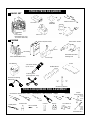 4
4
-
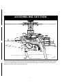 5
5
-
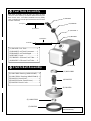 6
6
-
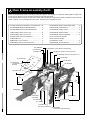 7
7
-
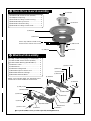 8
8
-
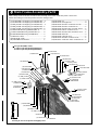 9
9
-
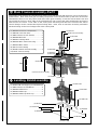 10
10
-
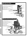 11
11
-
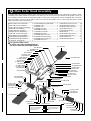 12
12
-
 13
13
-
 14
14
-
 15
15
-
 16
16
-
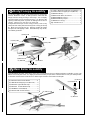 17
17
-
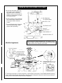 18
18
-
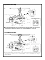 19
19
-
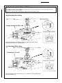 20
20
-
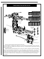 21
21
-
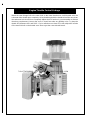 22
22
-
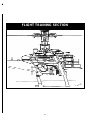 23
23
-
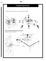 24
24
-
 25
25
-
 26
26
-
 27
27
-
 28
28
-
 29
29
-
 30
30
-
 31
31
-
 32
32
-
 33
33
-
 34
34
-
 35
35
-
 36
36
-
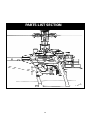 37
37
-
 38
38
-
 39
39
-
 40
40
-
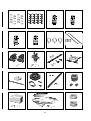 41
41
-
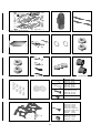 42
42
-
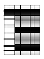 43
43
-
 44
44
-
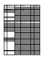 45
45
-
 46
46
-
 47
47
-
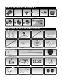 48
48
-
 49
49


THUNDER TIGER Raptor 30 V2 Assembly & Maintenance Manual
- Category
- Toys & accessories
- Type
- Assembly & Maintenance Manual
Ask a question and I''ll find the answer in the document
Finding information in a document is now easier with AI
Related papers
Other documents
-
brondell S1000-RW Installation guide
-
-
-
Hasbro Techno Zoids Electronic Storm Tiger Operating instructions
-
Merlin POLARIS 400CP User manual
-
Blade EFLH1527 User manual
-
Atdec APA-B Installation guide
-
-
Quick Quickie.15 User manual
-
Sea Eagle All-In-One Transformer Paddle Operating instructions