PAGE 5
© 2014 OJ Electronics A/S
QUICK START GUIDE
GUIDE DE DÉMARRAGE RAPIDE
GUÍA DE INICIO RÁPIDO
CLASSIFICATION
The product is a Class II device (enhanced insulation) and must be
connected to the following leads:
• Phase L1 (L) 120/240 V ±10%, 50/60 Hz
• Neutral L2 (N)
• Max. load 15 A (resistive load)
The terminals are suitable for field wiring cables of 12 to 22 AWG.
Heating element in accordance with the supply voltage.
TECHNICAL DATA
Supply Range ....................................................... 120/240 Vac 50/60 Hz
Load ................................................................max. 15 A (resistive load)
Max. power at e.g. .................................................... 1800 W at 120 Vac
.................................................................................. 3120 W at 208 Vac
.................................................................................. 3600 W at 240 Vac
GFCI ................................................................. Class A (5 mA trip level)
Temperature range ................................... +5 to +40°C / +41 to +104°F
Amb. temp. range ........................................ 0 to +25°C / +32 to +77°F
CERTIFICATION
UL Listed for the US and Canada
According to the following standards:
Thermostat: UL 873
CSA C22.2 No. 24.
UL file number: E157297
GFCI: UL 943 4th ed.
CSA C22.2 No. 144.1-06
Patent pending.
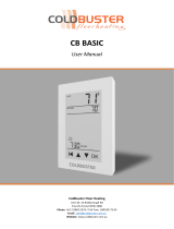
HOME SCREEN / ÉCRAN D’ACCUEIL / PANTALLA INICIAL
WARNINGS:
To avoid electric shock, disconnect the heating system power supply
at the main panel before installation and maintenance of the thermostat.
Keep thermostat air vents clean and free from obstruction. This ther-
mostat is an electrical device and must be installed in compliance with
national and/or local electrical codes. Installation must be performed by
qualified personnel where required by law.
AVERTISSEMENTS :
Pour éviter l’électrocution, coupez l’alimentation du système de chauf-
fage au panneau principal avant de faire l’installation et/ou l’entretien du
thermostat. Maintenez les évents du thermostat propres et libres d’obs-
truction. Ce thermostat est un appareil électrique et doit être installé
conformément aux codes électriques nationaux et/ou locaux. L’installa-
tion doit être eectuée par du personnel qualifié quand la loi l’exige.
ADVERTENCIAS:
Para evitar descargas eléctricas, desconecte el suministro de alimen-
tación eléctrica del sistema de calefacción en el panel principal antes
de la instalación y el mantenimiento del termostato. Mantenga limpios y
libres de cualquier obstrucciones los orificios de ventilación de aire del
termostato. Este termostato es un dispositivo eléctrico y debe instalarse
de conformidad con los códigos eléctricos nacionales y/o locales. La
instalación debe ser realizada por personal cualificado donde así lo
requiera la ley.
67370 02/15 (JRK)
OJ Electronics
Stenager 13B
DK-6400 Sønderborg
© 2015 OJ Electronics. All rights reserved.
This manual and parts thereof are protected under Danish and
international copyright laws.
© 2015 OJ Electronics. Tous droits réservés.
Ce manuel et son contenu sont protégés par les lois internationales et
danoises sur les droits d’auteur.
© 2015 OJ Electronics. Reservados todos los derechos.
Este manual y partes del mismo están protegidas en virtud de las leyes
danesas e internacionales sobre derechos de propiedad intelectual.
For support please contact your installer or retailer.
Pour le soutien, communiquez avec votre installateur ou votre
détaillant.
Para obtener soporte técnico, comuníquese con su instalador
o con el vendedor minorista.
http://www.ojelectronics.com/Products/Documents.aspx
CLASSIFICATION
Le produit est un appareil de classe II (isolation augmentée) et doit être
raccordé aux fils suivants :
• Phase L1 (L) 120/240 V ±10 %, 50/60 Hz
• Neutre L2 (N)
• Charge maximum 15 A (charge résistive)
Les borniers sont adéquats pour du câble de construction de 12 à 22
AWG. Élément chauant en fonction de la tension d’alimentation.
DONNÉES TECHNIQUES
Plage alimentation ..............................................120/240 VCA 50/60 Hz
Charge ........................................................ Max. 15 A (charge résistive)
Puissance maxi par exemple au ................................ 1800 W à 120 VCA
.................................................................................. 3120 W à 208 VCA
.................................................................................. 3600 W à 240 VCA
DDFT ......................................... Class A (niveau déclenchement 5 mA)
Plage de température ................................ +5 à +40 °C / +41 à +104 °F
Plage temp. amb. ............................................0 à +25 °C / +32 à +77 °F
CERTIFICATION
Homologué UL pour É.-U. et Canada
Selon les normes suivantes:
Thermostat: UL 873
CSA C22.2 No 24.
No. Dossier UL: E157297
DDFT: UL 943 4e ed.
CSA C22.2 No 144.1-06
En instance de brevet.
CLASIFICACIÓN
El producto es un dispositivo Clase II (aislamiento mejorado) y debe ser
conectado a los conductores siguientes:
• Fase L1 (L) 120/240 V ±10%, 50/60 Hz
• Neutro L2 (N)
• Carga máxima 15 A (carga resistiva)
Los terminales son adecuados para cables de cableado de campo, ca-
libre 12 a 22 AWG. Elemento calefactor de conformidad con el voltaje
de suministro.
DATOS TÉCNICOS
Rango alimentación eléctrica ............................120/240 V CA, 50/60 Hz
Carga ............................................................ máx. 15 A (carga resistiva)
Potencia maxima en el ejemplo ............................... 1800 W a 120 V CA
................................................................................. 3120 W a 208 V CA
................................................................................. 3600 W a 240 V CA
GFCI ..................................................... Clase A (nivel de disparo 5 mA)
Rango de temperatura ............................... +5 a +40 °C / +41 a +104 °F
Rango de temperatura ambiente .....................0 a +25 °C / +32 a +77 °F
CERTIFICACIÓN
En lista de UL para EE. UU. y Canadá
De conformidad con las normativas siguientes.
Termostato: UL 873
CSA C22.2 No. 24.
Número de archivo UL: E157297
GFCI: UL 943 4ta. edición
CSA C22.2 No. 144.1-06
Pendiente en trámite.
Scan the QR-code for full user manual.
Scannez le code QR pour obtenir le manuel
complet de l’utilisateur.
Escanee el código QR para obtener el manual
de usuario completo.
© 2015 OJ Electronics A/S · ® The OJ trademark is a registred trademark belonging to OJ Electronics A/S
1
3
4
5
6
7
8
2
Access Main Menu
Accès menu principal
Acceder al menú principal
GFCI Test Button
Bouton d’essai DDFT
Botón de prueba del GFCI
On/O/GFCI Reset Button
Press to turn system ON
Hold toturn system OFF
Press to reset the GFCI
Bouton de réarmement, marche/arrêt/DDFT
Appuyez pour mettre en marche le système
Tenez pour fermer le système
Appuyez pour réarmer le DDFT
Encendido/apagado/botón de restablecimiento del GFCI
Pulsar para encender (ON) el sistema
Pulsar sin soltar para apagar (OFF) el sistema
Pulsar para restablecer el GFCI
6
7
8
ITEMS / RÉF. / ELEMENTOS
Day and time
Jour et heure
Día y hora
Current temperature
Température actuelle
Temperatura actual
Target temperature or setpoint
Température cible ou point de consigne
Temperatura objetivo o punto de ajuste
Heating indicator - when visible, system is heating.
Indicateur de chauage - quand visible, chauage en marche.
Indicador de calefacción; al estar visible, el sistema está calentando
Next scheduled change
Prochain changement prévu
Próximo cambio programado
2
1
3
4
5
The thermostat has two physical buttons. A ground fault circuit interrupter (GFCI)
test button is located on top of the thermostat, and a power/reset button is located
on the right side of the thermostat.
The GFCI should be tested monthly (all settings, including time and date, will be
remembered).
The thermostat is an intuitively operated touch thermostat in which the touchscreen
is used to navigate through the menus and to change the settings.
The function of the buttons and icons on the home screen can be seen below.
4. General Operation