Page is loading ...

1
INSTALLATION AND OPERATION MANUAL
RECEIVING
The shipment should be thoroughly inspected as soon as it
is received. The signed Bill of Lading is acknowledgement
by the shipping carrier as receipt of this product as listed
in your invoice as being in a good condition of shipment. If
any of these goods listed on this Bill of Lading are missing
or damaged, do not accept goods until the shipping carrier
makes a notation on the freight bill of the missing or
damaged goods. Do this for your own protection.
BE SAFE
Your new lift was designed and built with safety in mind.
However, your overall safety can be increased with proper
training and thoughtful operation on the part of the operator.
DO NOT operate or repair this equipment without reading
this manual and the important safety instructions shown
inside. Keep this operation manual near the lift at all times.
Make sure that ALL USERS read and understand this
manual.
1645 Lemonwood Dr.
Santa Paula, CA. 93060, USA
Toll Free 1-800-253-2363
Tel: 1-805-933-9970
Fax: 1-805-933-9160
www.bendpak.com
IMPORTANT SAFETY INSTRUCTIONS
SAVE THESE INSTRUCTIONS
PLEASE READ THE ENTIRE CONTENTS OF THIS MANUAL PRIOR TO
INSTALLATION AND OPERATION. BY PROCEEDING WITH LIFT INSTALLATION
AND OPERATION YOU AGREE THAT YOU FULLY UNDERSTAND THE
FULL CONTENTS OF THIS MANUAL. FORWARD THIS MANUAL TO ALL
OPERATORS. FAILURE TO OPERATE THIS EQUIPMENT AS DIRECTED MAY
CAUSE INJURY OR DEATH.
MAN REV A 09-06-2016
P/N 5900951
10,000 LB /4536 KG CAPACITY
SURFACE MOUNTED TWO-POST LIFTS
MODELS:
XPR-10S
XPR-10S-LP
XPR-10S-168
XPR-10S-168-LP
XPR-10TS
XPR-10TS-168
XPR-10AS
XPR-10AS-LP
XPR-10AS-168
XPR-10AS-168-LP
400V 50Hz SUPPLY DETAILS ARE
INCLUDED WITH ELECTRICAL
CONTROL BOX. DISREGARD SUPPLY
WIRING DETAILS IN THIS MANUAL
EUROPEAN USERS
ORIGINAL INSTRUCTIONS IN
ENGLISH LANGUAGE
Keep this operation manual near the
machine at all times. Make sure that
ALL USERS read this manual.
Symmetrical
model shown
.

2
10,000 LB / 4536 KG CAPACITY SURFACE MOUNTED
TWO-POST AUTO LIFTS
This instruction manual has been prepared especially for you.
Your new lift is the product of over 40 years of continuous research, testing and development;
it is the most technically advanced lift on the market today.
READ THIS ENTIRE MANUAL BEFORE INSTALLATION & OPERATION BEGINS
RECORD HERE THE LIFT AND POWER UNIT INFORMATION
WHICH IS LOCATED ON THE
SERIAL NUMBER DATA PLATES ON THE LIFT AND
ON THE POWER UNIT
Power Unit Model # _____________
Power Unit Date Of Mfg. _____________
Power Unit Serial # _____________
Max Operating Pressure __2,650 PSI
This information is required when
calling for parts or warranty issues.
PRODUCT WARRANTY
Our comprehensive product warranty means more than a commitment to you; it’s also a commitment to the value of your
new BendPak lift. For full warranty details and to register your new lift contact your nearest BendPak dealer or visit:
http:/ / www.bendpak.com/ support/ warranty/
What is not covered under this warranty:
a. Any failure that results from Purchaser’s abuse, neglect or failure to operate, maintain or service product in
accordance with instructions provided in the owner’s manual(s) supplied.
b. Any damage caused by overloading lift beyond rated capacity.
c. Items or service normally required to maintain the product, i.e. lubricants, oil, etc.
d. Items considered general wear parts such as rubber pads, lifting cables, etc. unless wear or failure is a direct result
of manufacturer defect due to material and/or workmanship.
e. Any component damaged in shipment or any failure caused by installing or operating lift under conditions not in
accordance with installation and operation guidelines or damaged by contact with tools or surroundings.
f. Motor or pump failure caused by rain, excessive humidity, corrosive environments or other contaminants.
g. Rusted components due to improper maintenance or corrosive environments.
h. Cosmetic defects that do not interfere with product functionality.
i. Damage due to incorrect voltage or improper wiring.
j. Any incidental, indirect, or consequential loss, damage or expense that may result from any defect, failure or
malfunction of BendPak Inc. product.
k. All electrical components (excluding power unit) are guaranteed for one year against defects in workmanship and/or
materials when the lift is installed and used according to specifications.
Santa Paula, CA USA
www.bendpak.com
MODEL NUMBER
LIFT CAPACITY
SERIAL NUMBER
DESCRIPTION
VOLTAGE
DANGER!
Disconnect Power
Before Servicing
WARRANTY VOID IF DATA PLATE IS REMOVED
PN 5905950
110-240VAC, 50-60 Hz, 1 Ph 380-415VAC, 50-60 Hz, 3 Ph
208-240VAC, 50-60 Hz, 1 Ph 208-440VAC, 50-60 Hz, 3 Ph
DATE OF MFG.
NOTE:
Every effort has been taken to ensure complete and accurate instructions have been included in this manual, however,
possible product updates, revisions and or changes may have occurred since this printing. BendPak Ranger reserves
the right to change specications without incurring any obligation for equipment previously or subsequently sold.
Not responsible for typographical errors.

3
IMPORTANT NOTICE
Do not attempt to install this lift if you have never been
trained on basic automotive lift installation procedures.
Never attempt to lift components without proper lifting
tools such as forklift or cranes. Stay clear of any moving
parts that can fall and cause injury. These instructions
must be followed to insure proper installation and
operation of your lift. Failure to comply with these
instructions can result in serious bodily harm and void
product warranty. Manufacturer will assume no liability for
loss or damage of any kind, expressed or implied
resulting from improper installation or use of this product.
PLEASE READ ENTIRE MANUAL
PRIOR TO INSTALLATION
DEFINITIONS OF
HAZARD LEVELS
Identify the hazard levels used in this manual with the
following definitions and signal words:
Watch for this symbol: It Means: Immediate hazards
which will result in severe personal injury or death.
Watch for this symbol: It Means: Hazards or unsafe
practices which could result in severe personal
injury or death.
Watch for this symbol. It Means: Hazards or unsafe
practices which may result in minor personal injury,
product or property damage.
OWNER’S RESPONSIBILITY
To maintain the lift and user safety, the responsibility of
the owner is to read and follow these instructions:
t Follow all installation and operation instructions.
t Make sure installation conforms to all applicable Local,
State, and Federal Codes, Rules, and Regulations;
such as State and Federal OSHA Regulations and
Electrical Codes.
t Carefully check the lift for correct initial function.
t Read and follow the safety instructions. Keep them
readily available for machine operators.
t Make certain all operators are properly trained, know
how to safely and correctly operate the unit, and are
properly supervised.
t Allow unit operation only with all parts in place and
operating safely.
t Carefully inspect the unit on a regular basis and
perform all maintenance as required.
t Service and maintain the unit only with authorized or
approved replacement parts.
t Keep all instructions permanently with the unit and
all decals on the unit clean and visible.
BEFORE YOU BEGIN
Receiving:
The shipment should be thoroughly inspected as soon as it
is received. The signed bill of lading is acknowledgement by
the carrier of receipt in good condition of shipment covered
by your invoice. If any of the goods called for on this bill of
lading are shorted or damaged, do not accept them until the
carrier makes a notation on the freight bill of the shorted or
damaged goods. Do this for your own protection.
NOTIFY THE CARRIER AT ONCE if any hidden loss or
damage is discovered after receipt and request the carrier
to make an inspection. If the carrier will not do so, prepare
a signed statement to the effect that you have notified the
carrier (on a specific date) and that the carrier has failed to
comply with your request.
IT IS DIFFICULT TO COLLECT FOR LOSS OR DAMAGE
AFTER YOU HAVE GIVEN THE CARRIER A CLEAR
RECEIPT. File your claim with the carrier promptly. Support
your claim with copies of the bill of lading, freight bill,
invoice, and photographs, if available. Our willingness to
assist in helping you process your claim does not make
BendPak responsible for collection of claims or
replacement of lost or damaged materials.

4
TABLE OF CONTENTS
Warranty / Serial Number Information . . . . . . . . . . . . . . . . . . . . . . . . . . . . . . . . . . . . . . . . . . . . . . . . . . . . . . . . . . . . . . 2
Denitions of Hazard Levels . . . . . . . . . . . . . .. . . . . . . . . . . . . . . . . . . . . . . . . . . . . . . . . . . . . . . . . . . . . . . . . . . . . . . . 3
Owner’s Responsibility . . . . . . . . . . . . . . .. . . . . . . . . . . . . . . . . . . . . . . . . . . . . . . . . . . . . . . . . . . . . . . . . . . . . . . . . . 3
Before You Begin . . . . . . . . . . . . . . . . . . . . . . . . . . . . . . . . . . . . . . . . . . . . . . . . . . . . . . . . . . . . . . . . . . . . . . . . . . . . . 3
Installer/Operator Agreement/ Protective Equipment . . . . . . . . . . . . . . . . . . . . . . . . . . . . . . . . . . . . . . . . . . . . . . . . . 5
Introduction . . . . . . . . . . . . . . . . . . . . . . . . . . . . . . . . . . . . . . . . . . . . . . . . . . . . . . . . . . . . . . . . . . . . . . . . . . . . . . . . . . 6
Safety / Warning Instructions . . . . . . . . . . . . . . . . . . . . . . . . . . . . . . . . . . . . . . . . . . . . . . . . . . . . . . . . . . . . . . . . . . . . . 6
Tools Required . . . . . . . . . . . . . . . . . . . . . . . . . . . . . . . . . . . . . . . . . . . . . . . . . . . . . . . . . . . . . . . . . . . . . . . . . . . . . . . 7
Step 1 / Selecting Site . . . . . . . . . . . . . . . . . . . . . . . . . . . . . . . . . . . . . . . . . . . . . . . . . . . . . . . . . . . . . . . . . . . . . . . . . . 7
Step 2 / Floor Requirements . . . . . . . . . . . . . . . . . . . . . . . . . . . . . . . . . . . . . . . . . . . . . . . . . . . . . . . . . . . . . . . . . . . 7
Concrete Specications . . . . . . . . . . . . . . . . . . . . . . . . . . . . . . . . . . . . . . . . . . . . . . . . . . . . . . . . . . . . . . . . . . . . . . 7
Assembly View / Description of Parts . . . . . . . . . . . . . . . . . . . . . . . . . . . . . . . . . . . . . . . . . . . . . . . . . . . . . . . . . . . . . . 8
Floor Plan . . . . . . . . . . . . . . . . . . . . . . . . . . . . . . . . . . . . . . . . . . . . . . . . . . . . . . . . . . . . . . . . . . . . . . . . . . . . . . 9 - 11
Clearances . . . . . . . . . . . . . . . . . . . . . . . . . . . . . . . . . . . . . . . . . . . . . . . . . . . . . . . . . . . . . . . . . . . . . . . . . . .12 - 13
Step 3 / Post Preparation . . . . . . . . . . . . . . . . . . . . . . . . . . . . . . . . . . . . . . . . . . . . . . . . . . . . . . . . . . . . . . .14 - 15
Equalizer Cable Routing . . . . . . . . . . . . . . . . . . . . . . . . . . . . . . . . . . . . . . . . . . . . . . . . . . . . . . . . . . . . 16
Hose Routing . . . . . . . . . . . . . . . . . . . . . . . . . . . . . . . . . . . . . . . . . . . . . . . . . . . . . . . . . . . . 17
Step 4 / Site Layout . . . . . . . . . . . . . . . . . . . . . . . . . . . . . . . . . . . . . . . . . . . . . . . . . . . . . . . 18
Step 5 / Installing Power Side Post . . . . . . . . . . . . . . . . . . . . . . . . . . . . . . . . . . . . . . . . . . . . . . . .18 - 19
Step 6 / Installing Off Side Post . . . . . . . . . . . . . . . . . . . . . . . . . . . . . . . . . . . . . . . . . . . . . . . . . . . . . . . 19
Step 7 / Mounting The Overhead Assembly . . . . . . . . . . . . . . . . . . . . . . . . . . . . . . . . . . . . . . . . . . . . . . . . . . . 19 - 20
Step 8 / Mounting The Hydraulic Power Unit . . . . . . . . . . . . . . . . . . . . . . . . . . . . . . . . . . . . . . . . . . . . . . . 20 - 21
Step 9 / Installing the Safeties and Safety Cable . . . . . . . . . . . . . . . . . . . . . . . . . . . . . . . . . . . . . . . . . . . .21 - 22
Step 10 / Installing Hydraulic Lines . . . . . . . . . . . . . . . . . . . . . . . . . . . . . . . . . . . . . . . . . . . . . . . . . . . . . . . . . . . . . 23
Step 11 / Routing the Equalizer Cables . . . . . . . . . . . . . . . . . . . . . . . . . . . . . . . . . . . . . . . . . . . . . . . . . . . . . . . 23 - 24
Step 12 / Installing Overhead Microswitch . . . . . . . . . . . . . . . . . . . . . . . . . . . . . . . . . . . . . . . . . . . . . . . . . . . . . . . . 24 - 25
Step 13 / Installing Power Unit Hose Assembly and Power Side Safety Cover . . . . . . . . . . . . . . . . . . . 25 - 26
Step 14 / Installing the Lift Arms . . . . . . . . . . . . . . . . . . . . . . . . . . . . . . . . . . . . . . . . . . . . . . . . . . . . . . 26 - 27
Carriage Stop Bolt Installation Warning. . . . . . . . . . . . . . . . . . . . . . . . . . . . . . . . . . . . . . . . . . . . . . . . . . . . . . . .28 - 29
Step 15 / Power Unit Connection . . . . . . . . . . . . . . . . . . . . . . . . . . . . . . . . . . . . . . . . . . . . . . . . . . . . . . . . . . . 30 - 32
Step 16 / Lift Start Up Final Adjustments . . . . . . . . . . . . . . . . . . . . . . . . . . . . . . . . . . . . . . . . . . . . . . . . . . . . . . . . . . . . . 32
Post Installation Checklist . . . . . . . . . . . . . . . . . . . . . . . . . . . . . . . . . . . . . . . . . . . . . . . . . . . . . . . . . . . . . . . . . . . . . . . . . 33
Step 17 / Lubrication. . . . . . . . . . . . . . . . . . . . . . . . . . . . . . . . . . . . . . . . . . . . . . . . . . . . . . . . . . . . . . . . . . . . . . . . . . . 33
Step 18 / Bleeding the Cylinders . . . . . . . . . . . . . . . . . . . . . . . . . . . . . . . . . . . . . . . . . . . . . . . . . . . . . . . . . . . . . . 33
Optional Equipment Installation / Optional Accessories . . . . . . . . . . . . . . . . . . . . . . . . . . . . . . . . . . . . . . . . . . 34 - 36
Step 19 / Operation/ Maintenance . . . . . . . . . . . . . . . . . . . . . . . . . . . . . . . . . . . . . . . . . . . . . . . . . . . . . . . . . . . 37 - 47
Troubleshooting Guide . . . . . . . . . . . . . . . . . . . . . . . . . . . . . . . . . . . . . . . . . . . . . . . . . . . . . . . . . . . . . . . . . . . . . 48 - 51
Torque Recommendations . . . . . . . . . . . . . . . . . . . . . . . . . . . . . . .. . . . . . . . . . . . . . . . . . . . . . . . . . . . . . 51
Installation Form . . . . . . . . . . . . . . . . . . . . . . . . . . . . . . . . . . . . . . . . . . . . . . . . . . . . . . . . . . . . . . . . . . . . . . . . . . . . . 52
Part Number Lists . . . . . . . . . . . . . . . . . . . . . . . . . . . . . . . . . . . . . . . . . . . . . . . . . . . . . . . . . . . . . . . . . . . . . . . . 53 - 73
CE Certicate . . . . . . . . . . . . . . . . . . . . . . . . . . . . . . . . . . . . . . . . . . . . . . . . . . . . . . . . . . . . . 74
Declaration of Conformity . . . . . . . . . . . . . . . . . . . . . . . . . . . . . . . . . . . . . . . . . . . . . . . . . . . . . . . . . . . . . 75

55
INSTALLER / OPERATOR
PLEASE READ AND FULLY
UNDERSTAND.
BY PROCEEDING YOU AGREE TO
THE FOLLOWING:
t I have visually inspected the site where the lift is to be
installed and verified the concrete to be in good
condition and free of cracks or other defects. I understand
that installing a lift on cracked or defective concrete could
cause lift failure resulting in personal injury or death.
t I understand that a level floor is required for proper
installation and level lifting.
t I understand that I am responsible if my floor is of
questionable slope and that I will be responsible for all
charges related to pouring a new level concrete slab if
required and any charges.
t I understand that the lifts are supplied with concrete
fasteners meeting the criteria of the American National
Standard “Automotive Lifts - Safety Requirements for
Construction, Testing, and Validation” ANSI/ALI ALCTV-
2011, and that I will be responsible for all charges related
to any special regional structural and/or seismic anchor-
ing requirements specified by any other agencies and/or
codes such as the Uniform Building Code (UBC) and/or
International Building Code (IBC).
t I will assume full responsibility for the concrete floor
and condition thereof, now or later, where the above
equipment model(s) are to be installed. Failure to follow
danger, warning, and caution instructions may lead to
serious personal injury or death to operator or bystander
or damage to property.
t I understand that Bendpak lifts are designed to be
installed in indoor locations only. Failure to follow
installation instructions may lead to serious personal
injury or death to operator or bystander or damage to
property or lift.
Failure to follow danger, warning, and caution
instructions may lead to serious personal injury or death
to operator or bystander or damage to property.
Please read entire manual prior to installation.
Do not operate this machine until you read and
understand all the dangers, warnings and cautions
in this manual.
For additional copies
or further information, contact:
BendPak Inc. / Ranger Products
1645 Lemonwood Dr.
Santa Paula, CA. 93060
1-805-933-9970
www.bendpak.com
INSTALLER / OPERATOR
PROTECTIVE EQUIPMENT
Personal protective equipment helps makes installation
and operation safer, however, it does not take the place
of safe operating practices. Always wear durable work
clothing during any installation and/or service activity.
Shop aprons or shop coats may also be worn, however,
loose fitting clothing should be avoided. Tight fitting
leather gloves are recommended to protect technician
hands when handling parts. Sturdy leather work shoes
with steel toes and oil resistant soles should be used by
all service personnel to help prevent injury during typical
installation and operation activities.
Eye protection is essential during
installation and operation activities.
Safety glasses with side shields,
goggles, or face shields are acceptable.
Back belts provide support during lifting
activities and are also helpful in
providing worker protection. Consideration should also be
given to the use of hearing protection if service activity is
performed in an enclosed area or if noise levels are high.
THIS SYMBOL POINTS OUT IMPORTANT SAFETY INSTRUCTIONS WHICH IF NOT FOLLOWED
COULD ENDANGER THE PERSONAL SAFETY AND/OR PROPERTY OR YOURSELF AND OTHERS
AND CAN CAUSE PERSONAL INJURY OR DEATH. READ AND FOLLOW ALL INSTRUCTIONS IN
THIS MANUAL BEFORE ATTEMPTING TO OPERATE THIS MACHINE.

66
INTRODUCTION
1. Read and understand all instructions and all safety
warnings before operating lift.
2. Care must be taken as burns can occur from touching
hot parts.
3. Do not operate equipment with a damaged cord or if the
equipment has been dropped or damaged until it has been
examined by a qualied service person.
4. Do not let a cord hang over the edge of the table, bench,
or counter or come in contact with hot manifolds or moving
fan blades.
5. If an extension cord is necessary, a cord with a current
rating equal to or more than that of the equipment should be
used. Cords rated for less current than the equipment may
overheat. Care should be taken to arrange the cord so that it
will not be tripped over or pulled.
6. Always unplug equipment from electrical outlet when not
in use. Never use the cord to pull the plug from the outlet.
Grasp plug and pull to disconnect.
7. Let equipment cool completely before putting away. Loop
cord loosely around equipment when storing.
8. To reduce the risk of re, do not operate equipment in the
vicinity of open containers of ammable liquids (gasoline).
9. Adequate ventilation should be provided when working
on operating internal combustion engines.
10. Keep hair, loose clothing, ngers, and all parts of body
away from moving parts. Keep feet clear of lift when lowering.
Avoid pinch points.
11. DANGER! To reduce the risk of
electric shock, do not use on wet surfaces
or expose to rain. The power unit used on
this lift contains high voltage. Disconnect
power at the receptacle or at the circuit
breaker switch before performing any elec-
trical repairs. Secure plug so that it cannot
be accidentally plugged in during service, or
mark circuit breaker switch so that it cannot
be accidentally switched on during service.
12. Use only as described in this manual.
Use only manufacturer’s recommended attachments.
13. ALWAYS WEAR SAFETY GLASSES. Everyday
eyeglasses only have impact resistant lenses, they are not
safety glasses.
14. Consider work environment. Keep work area clean.
Cluttered work areas invite injuries. Keep areas well lit.
15. Guard against electric shock. This lift must be grounded
while in use to protect operator from electric shock. Never
connect the green power cord wire to a live terminal. This is
for ground only.
16. Only trained operators should operate this lift. All
non-trained personnel should be kept away from the work
area. Never let non-trained personnel come in contact with,
or operate lift.
17. DO NOT override self-closing lift controls.
18. Clear area if vehicle is in danger of falling.
19. ALWAYS make sure the safeties are engaged before
attempting to work on or near a vehicle.
21. WARNING! RISK OF EXPLOSION. This
equipment has internal arcing or sparking
parts which should not be exposed to am-
mable vapors. This machine should not be
located in a recessed area or below oor
level.
22. MAINTAIN WITH CARE. Keep lift clean for better and
safer performance. Follow manual for proper lubrication and
maintenance instructions. Keep control handles and/or
buttons dry, clean and free from grease and oil.
23. Check for damaged parts. Check for alignment of
moving parts, breakage of parts or any condition that may
affect operation of lift. Do not use lift if any component is
broken or damaged.
24. NEVER remove safety related components from the lift.
Do not use lift if safety related components are missing or
damaged.
23. STAY ALERT. Use common sense and watch what you
are doing. Remember, SAFETY FIRST.
SAVE THESE INSTRUCTIONS
1. Carefully remove the crating and packing
materials. CAUTION! Be careful when cutting steel
banding material as items may become loose and fall
causing personal harm or injury.
2. Check the voltage, phase and proper amperage
requirements for the motor shown on the motor plate.
Wiring should be performed by a certied electrician only.
IMPORTANT SAFETY INSTRUCTIONS
Read these safety instructions entirely
IMPORTANT NOTICE
Do not attempt to install this lift if you have never been trained on basic automotive lift installation procedures.
Never attempt to lift components without proper lifting tools such as forklift or cranes.
Stay clear of any moving parts that can fall and cause injury.

77
STEP 1
(Selecting Site)
Before installing your new lift, check the following.
1. LIFT LOCATION: Always use architect’s plans when
available. Check layout dimension against oor plan
requirements making sure that adequate space is
available.
2. OVERHEAD OBSTRUCTIONS: The area where the
lift will be located should be free of overhead obstructions
such as heaters, building supports, electrical lines etc.
3. DEFECTIVE FLOOR: Visually inspect the site where
the lift is to be installed and check for cracked or defective
concrete.
4. Lift is designed for INDOOR INSTALLATION ONLY.
Outdoor use permitted only if covered and dry. Always fol-
low warnings illustrated on equipment labels.
STEP 2
(Floor Requirements)
This lift must be installed on a solid level concrete oor
with no more than 3°s of slope. Failure to do so could
cause personal injury or death.
A level oor is suggested for proper use and installation
and level lifting. If a oor is of questionable slope, consider
a survey of the site and/or the possibility of pouring a new
level concrete slab.
t DO NOT install or use this lift on any asphalt surface
or any surface other than concrete.
t DO NOT install or use this lift on expansion seams
or on cracked or defective concrete.
t DO NOT install or use this lift on a second / elevated
oor without rst consulting a building architect.
LIFT MODEL CONCRETE REQUIREMENTS
XPR-10S/10AS SERIES 4” Min. Thickness / 3,000 PSI
ALL MODELS MUST BE INSTALLED ON 3000 PSI
CONCRETE ONLY CONFORMING TO THE
MINIMUM REQUIREMENTS SHOWN ABOVE.
NEW CONCRETE MUST BE ADEQUATELY CURED
FOR A MINIMUM OF 28 DAYS.
IMPORTANT NOTICE
THESE INSTRUCTIONS MUST BE FOLLOWED TO INSURE PROPER INSTALLATION AND OPERATION OF YOUR LIFT.
FAILURE TO COMPLY WITH THESE INSTRUCTIONS CAN RESULT IN SERIOUS BODILY HARM AND VOID PRODUCT
WARRANTY. MANUFACTURER WILL ASSUME NO LIABILITY FOR LOSS OR DAMAGE OF ANY KIND, EXPRESSED OR
IMPLIED, RESULTING FROM IMPROPER INSTALLATION OR USE OF THIS PRODUCT.
PLEASE READ ENTIRE MANUAL PRIOR TO INSTALLATION
t Rotary Hammer Drill or Similar
t 3/4” Masonry Bit
t Hammer
t 4 Foot Level
t Open-End Wrench Set: SAE/Metric
t Socket And Ratchet Set: SAE/Metric
t Hex-Key / Allen Wrench Set
t Large Crescent Wrench
t Large Pipe Wrench
t Crow Bar
t Chalk Line
t Medium Flat Screwdriver
t Tape Measure: 25 Foot Minimum
t Needle Nose Pliers
TOOLS REQUIRED
IMPORTANT NOTE
BendPak lifts are supplied with installation instructions and concrete fasteners meeting the criteria as prescribed by the
American National Standard "Automotive Lifts - Safety Requirements for Construction, Testing, and Validation" ANSI/ALI
ALCTV-2011. Lift buyers are responsible for any special regional structural and/or seismic anchoring requirements specied
by any other agencies and/or codes such as the Uniform Building Code (UBC) and/or International Building Code (IBC).
CONCRETE SPECIFICATIONS

88
When removing the lift from shipping angles, pay close attention as the posts can slide and can cause injury. Prior
to removing the bolts make sure the posts are held securely by a fork lift or some other heavy lifting device.
PARTS INVENTORY
Be sure to take a complete inventory of parts prior to beginning installation.
Description Qty
Overhead Assembly 1
Front Lift Arm Assembly 2
Rear Lift Arm Assembly 2
Off Side Post with Carriage Assembly 1
Power Side Post with Carriage Assembly 1
Hydraulic Cylinder 2
Parts Box (Packing List Enclosed) 1
Parts Bag (Packaged in Part Box) 1
Hydraulic Power Unit 1
Overhead
Assembly
Off Side Post
Assembly
Post Extension
Weldments
Power Side Post
Assembly
Hydraulic
Power Unit
Telescoping
Screw Pad
Front and Rear
Arm Assemblies
Stacking Pad
Adapters

9
FLOOR PLAN
MODEL XPR-10S XPR-10TS XPR-10S-LP
Lifting Capacity 10,000Lbs. / 4536Kg. 10,000Lbs. / 4536Kg. 10,000Lbs. / 4536Kg.
Max Capacity/ Front Axle 5,000Lbs. / 2268Kg. 5,000Lbs. / 2268Kg. 5,000Lbs. / 2268Kg.
Max Capacity/ Rear Axle 5,000Lbs. / 2268Kg. 5,000Lbs. / 2268Kg. 5,000Lbs. / 2268Kg.
A- Height Overall(*): 145" / 3683mm. (*) 145” / 3683mm. (*) 145” / 3683mm. (*)
B -Width Overall -NARROW CONFIGURATION 132" / 3353mm. 132" / 3353mm. 132" / 3353mm.
B -Width Overall -WIDE CONFIGURATION 145" / 3683mm. 145" / 3683mm. 145" / 3683mm.
D- Floor to Overhead Switch: 141" / 3581mm. (*) 141" / 3532mm. (*) 141” / 3532mm.(*)
F -Reach (Front Arm Min.): 27-1/2" / 698mm. 27-1/2” / 698mm. 28-1/2” / 724mm
G -Reach (Front Arm Max.): 51-1/2" / 1308mm. 51-1/2” / 1308mm. 47-1/2" / 1206mm.
H- Reach (Rear Arm Min.): 34" / 863mm. 27-1/2” / 698mm. 28-1/2" / 698mm.
I- Reach (Rear Arm Max.): 54-1/2" / 1384mm. 51-1/2" / 1308mm. 47-1/2" / 1206mm.
J- Min. Pad Height:
4.25" - 6-3/4” / 102mm 4.25 - 6-3/4" / 102mm. 4.25 - 6-3/4” / 102mm.
Screw Pad Adjustment 2” / 51mm 2” / 51mm 2” / 51mm
K- Rise: 69" / 1753mm. 69" / 1753mm. 69" / 1753mm.
L -Max Lift Height (Pad Only):
73"- 75”/1854mm-1905mm 73”- 75”/1854mm-1905mm
73”-75”/1854mm-1905mm
M - Max Lift Height (3" Adapter):
75.5”-77.5”/1917mm-1968 75.5”-77.5”/1917mm-1968 75.5”-77.5”/1917mm-1968
Standard Motor(**) 220VAC / 60Hz.1Ph. 220VAC / 60Hz.1Ph. 220VAC / 60Hz.1Ph.
Time of Full Rise: 45 Seconds 45 Seconds 45 Seconds
Max Load Per Arm: 2,500Lbs. / 1134Kg. 2,500Lbs. / 1134Kg. 2,500Lbs. / 1134Kg.
Emission sound pressure at Operator Position < 70 dB(A)
* An optional bolt-on top extension for columns raises the overhead bar an additional 24”. Must be ordered from factory at time of order.
** Special Voltages Available Upon Request
The design, material and specications are subject to change without notice.

10
FLOOR PLAN
MODEL XPR-10S-168 XPR-10TS-168 XPR-10S-168-LP
Lifting Capacity 10,000Lbs. / 4536Kg. 10,000Lbs. / 4536Kg. 10,000Lbs. / 4536Kg.
Max Capacity/ Front Axle 5,000Lbs. / 2268Kg. 5,000Lbs. / 2268Kg. 5,000Lbs. / 2268Kg.
Max Capacity/ Rear Axle 5,000Lbs. / 2268Kg. 5,000Lbs. / 2268Kg. 5,000Lbs. / 2268Kg.
A- Height Overall(*): 169" / 4293mm. 169” / 4293mm. 169” / 4293mm.
B -Width Overall -NARROW CONFIGURATION 132" / 3353mm. 132" / 3353mm. 132" / 3353mm.
B -Width Overall -WIDE CONFIGURATION 145" / 3683mm. 145" / 3683mm. 145" / 3683mm.
D- Floor to Overhead Switch: 165" / 4191mm. 165” / 4191mm.(*) 165” / 4191mm.(*)
F -Reach (Front Arm Min.): 27-1/2" / 698mm. 27-1/2” / 698mm. 28-1/2” / 724mm.
G -Reach (Front Arm Max.): 51-1/2" / 1308mm. 51-1/2” / 1308mm. 47-1/2" / 1206mm.
H- Reach (Rear Arm Min.): 34" / 863mm. 27-1/2" / 698mm. 28-1/2" / 724mm.
I- Reach (Rear Arm Max.): 54-1/2" / 1384mm. 51-1/2" / 1308mm. 47-1/2" / 1206mm.
J- Min. Pad Height: 4" / 102mm. 4" / 102mm. 4-1/4" / 110mm.
K- Rise: 69" / 1753mm. 69" / 1753mm. 69" / 1753mm.
L -Max Lift Height (Pad Only):
73”- 75”/1854mm-1905mm 73”- 75”/1854mm-1905mm 73”- 75”/1854mm-1905mm
M - Max Lift Height (6" Adapter):
75.5”-77.5”/1917mm-1968 75.5”-77.5”/1917mm-1968 75.5”-77.5”/1917mm-1968
Standard Motor(**) 220VAC / 60Hz.1Ph. 220VAC / 60Hz.1Ph. 220VAC / 60Hz.1Ph.
Time of Full Rise: 45 Seconds 45 Seconds 45 Seconds
Max Load Per Arm: 2,500Lbs. / 1134Kg. 2,500Lbs. / 1134Kg. 2,500Lbs. / 1134Kg.
Emission sound pressure at Operator Position < 70 dB(A)
* An optional bolt-on extension for columns raises the overhead bar an additional 24”. Must be ordered from factory at time of order.
** Special Voltages Available Upon Request.
The design, material and specications are subject to change without notice.

11
FLOOR PLAN
MODEL XPR-10AS XPR-10AS-168 XPR-10AS-LP XPR-10AS-168-LP
Lifting Capacity
10,000Lbs. / 4536Kg. 10,000Lbs. / 4536Kg. 10,000Lbs. / 4536Kg. 10,000Lbs. / 4536Kg.
Max Capacity/ Front Axle
5,000Lbs. / 2268Kg. 5,000Lbs. / 2268Kg. 5,000Lbs. / 2268Kg. 5,000Lbs. / 2268Kg.
Max Capacity/ Rear Axle
5,000Lbs. / 2268Kg. 5,000Lbs. / 2268Kg. 5,000Lbs. / 2268Kg. 5,000Lbs. / 2268Kg.
A- Height Overall:
145" / 3683 mm. (*) 169" / 4293mm. 145" / 3683mm. (*) 169” / 4293mm.
B -Width Overall -NARROW
CONFIGURATION
137" / 3480mm. 137" / 3480mm. 137" / 3480mm. 137" / 3480mm.
B -Width Overall -WIDE CONFIGURATION
145" / 3683mm. 145" / 3683mm. 145" / 3683mm. 145" / 3683mm.
D- Floor to Overhead Switch:
141" / 3581mm. (*) 165" / 4191mm. 141" / 3581mm. (*) 165" / 4191mm.(*)
F -Reach (Front Arm Min.):
23-1/2" / 597mm. 23-1/2" / 597mm.
23-1/2” / 597mm. 23-1/2" / 597mm.
G -Reach (Front Arm Max.):
45-1/2" / 1156mm. 45-1/2” / 1156mm.
38-1/2" / 978mm. 38-1/2" / 978mm.
H- Reach (Rear Arm Min.):
42-1/2" / 1079mm. 42-1/2” / 1079mm. 34-1/2" / 876mm. 34-1/2" / 876mm.
I- Reach (Rear Arm Max.):
60" / 1524mm. 60" / 1524mm. 54-1/2" / 1384mm. 54-1/2" / 1384mm.
J- Min. Pad Height:
4" / 102mm. 4" / 102mm.
4" / 102mm. 4" / 102mm.
Screw Pad Adjustment
2” / 51mm. 2” / 51mm.
2” / 51mm. 2” / 51mm.
K- Rise:
69" / 1753mm. 69" / 1753mm.
69" / 1753mm. 69" / 1753mm.
L -Max Lift Height (Pad Only):
73”-75”/ 1854-1905mm. 73”-75”/ 1854-1905mm.
73”-75”/ 1854-1905mm. 73”-75”/ 1854-1905mm.
M - Max Lift Height (6" Adapter):
75.5”-77.5”/1917mm-1968 75.5”-77.5”/1917mm-1968
75.5”-77.5”/1917mm-1968
75.5”-77.5”/1917mm-1968
Standard Motor(**)
220VAC / 60Hz.1Ph. 220VAC / 60Hz.1Ph. 220VAC / 60Hz.1Ph. 220VAC / 60Hz.1Ph.
Time of Full Rise:
45 Seconds 45 Seconds 45 Seconds 45 Seconds
Max Load Per Arm:
2,500Lbs. / 1134Kg. 2,500Lbs. / 1134Kg. 2,500Lbs. / 1134Kg. 2,500Lbs. / 1134Kg.
Emission sound pressure at Operator Position < 70 dB(A).
* An optional bolt-on extension for columnn raises the overhead bar an additional 24”. Must be ordered from factory at time of order.
** Special Voltages Available Upon Request. The design, material and specications are subject to change without notice.
The design, material and specications are subject to change without notice.
NOTE: Power Unit MUST go only where X is located.
X

12
LIFT HEIGHT CLEARANCE NOTE: There must be a 1” MIN distance from top of lift to nearest obstruction.
CLEARANCES
XPR-10S

13
LIFT HEIGHT CLEARANCE NOTE: There must be a 1” MIN. distance from top of lift to nearest obstruction.
CLEARANCES
XPR-10AS

1414
STEP 3
(Post Preparation)
COMPLETE THE FOLLOWING
PRIOR TO RAISING THE POSTS
1. Prior to raising posts, slide each carriage upwards to
aid in sheave removal and equalizer cable routing.
2. Remove the cable sheaves located at the inside
bottom of each post.
3. Identify the correct cable button on the end of each
equalizer cable that corresponds to your desired lift
conguration. Route the button around the bottom sheave
and secure at the carriage lock plate located inside each
carriage.
4. Route threaded end of cable upwards through the
bottom of the carriage. Leave excess cable resting on top of
carriage until further steps are required. (See Fig 3.5)
Fig 3.4
NOTE:
DETERMINE DESIRED LOCATION AND WIDTH
LAYOUT BEFORE RAISING POSTS. REFER TO
LAYOUT CHARTS ON PAGE 12.
NOTE:
SYMMETRICAL MODELS BOTH CABLES ARE SAME
LENGTH. ASYMMETRIC MODELS HAVE TWO
DIFFERENT LENGTH CABLES. (SEE FIG. 3.4)
Fig 3.5
Slide carriage
upwards
Remove cable sheaves
For narrow conguration
For wide conguration
To threaded
cable end
For Asymmetric Models Only
Long cable on lock plate
THIS SIDE
Short cable on lock plate
THIS SIDE
For Wide
conguration,
lock cable button
into second
button position
into Lock Plate
inside of the
carriage.
Threaded
end of cable
routed up
through
carriage
towards
Overhead
Assembly.
NOTE: Portions of Carriage and Post cut away for clarity
Fig 3.3
Fig 3.2
Fig 3.1
Fig 3.6
Threaded end of
cable routed up
through carriage
towards Overhead
Assembly.
For Narrow
conguration,
lock cable
button into rst
button position
into Lock Plate
inside of the
carriage.
NOTE: Portions of Carriage and Post cut away for clarity
NOTE: Second Cable Button should be tucked away from
the lifting cable route. Second Cable Button in Fig 3.6
shown for representational purposes only.

15
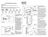
5. Install the cylinder ttings in cylinder ports. Pay attention
when installing the ttings to ensure that each tting points
towards the side of the post that the hose retainer clips are
located on. (See Fig 3.7)
6. Route both hoses in their respective posts PRIOR to
raising posts to their vertical position. When routing the
hydraulic hoses through the post, make sure to route
through the hose clips welded inside each post. Make
sure that the hoses are clear of any moving parts. It
may be necessary to tie hoses clear of obstructions by
using nylon tie straps or wire. Refer to Step 10 for further
instructions.
Fig 3.7
Fitting must be
turned towards
hose clips for
hydraulic hose
routing
NOTE: Portions of Post cut away for clarity
Notice that
the hose clips
are offset for
hydraulic hose
routing
NOTE FOR EXTENDED HEIGHT MODELS:
FOR XPR-10S-168, XPR-10AS-168, XPR-10TS-168,
XPR-10S-168-LP, XPR-10AS-LP-168 MODELS, FIT
EXTENSION WELDMENTS TO POST ASSEMBLY
IN THIS STEP FOR EASE OF INSTALLATION
AND BOLT TOGETHER AS SHOWN BELOW
WITH M12 HARDWARE.
M12 Hex
Head Bolt
M12 Spring
Lock Washer
M12 Flat
Washer
M12 Hex
Nut
Fig 3.8
BE SURE TO ROUTE THE HYDRAULIC HOSES
THROUGH THE HOSE CLIPS WELDED
INSIDE EACH POST.

16
NOTE:
XPR -10S models: both Equalizer Cables are the same length.
Overhead Assembly sheaves ARE NOT staggered.
XPR-10AS models: have one short and one long Equalizer Cable.
Overhead Assembly sheaves ARE staggered.
EQUALIZER CABLE ROUTING
XPR-10AS wide conguration shown.
SHORT CABLE
(“A” Models)
THREADED END
BUTTON END
LONG CABLE
(“A” Models)
POWERSIDEOFFSIDE

17
HOSE ROUTING

1818
STEP 4
(Site Layout)
1. Determine which side of the lift will be the approach side.
2. Now determine where the power unit will be located.
The POWER SIDE column has the power unit mounting
bracket attached to the side.
3. Use the chart on page 12 to determine which lift width
layout you would like to use. Also, you can see image above
for reference.
4. Once a location is determined, use a carpenter’s chalk
line to layout an alignment line for the post locations. Keep
all dimensions square within 1/8” (3mm) or malfunction of
the lift can occur. (See Fig 4.1)
5. After the post locations are properly marked, use chalk
or crayon to make an outline of the posts on the oor at each
post location using the post base plates as a template.
6. CHECK ALL DIMENSIONS TWICE and make sure that
the layout is perfectly square.
STEP 5
(Installing the POWER SIDE post)
1. Before proceeding, double check measurements and
make certain that the base plate of each post is aligned
with the chalk line.
CHALK LINE
CHALK LINE
FOR XPR-10AS CONFIGURATIONS USE NOTCHES TO ALIGN POSTS.
FOR XPR-10S CONFIGURATIONS USE BASE PLATE EDGES TO ALIGN POSTS.
NOTE:
BENDPAK LIFTS ARE SUPPLIED WITH
INSTALLATION INSTRUCTIONS AND CONCRETE
FASTENERS MEETING THE CRITERIA AS
PRESCRIBED BY THE AMERICAN NATIONAL
STANDARD "AUTOMOTIVE LIFTS - SAFETY
REQUIREMENTS FOR CONSTRUCTION, TESTING,
AND VALIDATION" ANSI/ALI ALCTV-2011. LIFT
BUYERS ARE RESPONSIBLE FOR ANY SPECIAL
REGIONAL STRUCTURAL AND/OR SEISMIC
ANCHORING REQUIREMENTS SPECIFIED BY ANY
OTHER AGENCIES AND/OR CODES SUCH AS THE
UNIFORM BUILDING CODE (UBC) AND/OR
INTERNATIONAL BUILDING CODE (IBC).
OUTSIDE
BASEPLATE
OUTSIDE
BASEPLATE
OUTSIDE
BASEPLATE
OUTSIDE
BASEPLATE
Fig 4.1

1919
2. Using the baseplate on the POWER SIDE post as a
guide, drill each anchor hole in the concrete approximately
4” deep for 10K models using a rotary hammer drill and 3/4”
concrete drill-bit. To ensure full holding power, do not ream
the hole or allow the drill to wobble. (See Fig. 5.1)
3. After drilling, remove dust thoroughly from each hole
making certain that the posts remain aligned with the
chalk line.
4. Assemble the washers and nuts on the anchors then
tap into each hole with a hammer until the washer rests
against the base plate. If shimming is required, be sure
that enough threads are left exposed. (See Fig. 5.2)
5. If shimming is required, insert the shims as necessary
under the base plate so that when the anchor bolts are
tightened, the posts will be plumb. (See Fig. 5.3)
6. If installing the optional foot guards, place foot guards
on left and right side as shown. (See Fig 5.4)
7. With the foot guards, shims and anchor bolts in place,
tighten by securing the nut to the base then turning 3-5 full
turns clockwise. DO NOT use an impact wrench for this pro-
cedure. (See Fig. 5.5)
STEP 6
(Installing the OFF SIDE post)
1. Position the OFF SIDE post at the designated chalk
locations and secure post to the oor following the same
procedures as outlined in STEP 5: Paragraphs 1-6.
STEP 7
(Mounting the Overhead Assembly)
1. Remove all of the equalizer cable sheaves in
preparation for the installation of the Overhead Assembly.
Fig 5.1
Fig 5.2
Fig 5.3
Fig 5.4
Fig 5.5
NOTE:
TO EASE THE INSTALLATION OF THE OVERHEAD
ASSEMBLY, IT HELPS TO KEEP THE ANCHOR BOLTS
LOOSE ON ONE OF THE POSTS UNTIL THE OVER-
HEAD ASSEMBLY IS MOUNTED.
NOTE:
IN ORDER TO ROUTE THE EQUALIZER CABLES
THE SHEAVES MUST BE REMOVED.
NOTE:
TO EASE INSTALLATION OF THE OVERHEAD
ASSEMBLY, IT HELPS TO KEEP THE ANCHOR
BOLTS LOOSE ON ONE OF THE POSTS UNTIL THE
OVERHEAD ASSEMBLY IS MOUNTED.
TAP ANCHOR BOLTS INTO
EACH HOLE WITH A HAMMER
UNTIL THE WASHER RESTS
AGAINST THE BASEPLATE.
TIGHTEN NUT
3-5 TURNS.
DO NOT USE
IMPACT WRENCH.

20
2. Adjust the Overhead Assembly width to match either
the Narrow or Wide conguration, and loosely tighten bolts.
(See Fig 7.1)
3. Using a lifting device, raise the Overhead Assembly
into position on top of the posts. Bolt Overhead Assembly
to the posts using the provided M10 hex head bolts, nuts
and washers.
4. YOU MUST POSITION THE SWITCH ENCLOSURE
ADJACENT TO POWER SIDE POST. (See Fig. 7.2)
5. Tighten the Overhead Assembly bolts.
STEP 8
(Mounting the Hydraulic Power Unit)
1. Attach the power unit to the POWER SIDE post. Install
the vibration dampener between the power unit and the
power unit mounting plate on the Power Side post, using
four M8 hex head bolts and nuts supplied. (See Fig 8.1)
2. Fill the reservoir with 10 WT. HYDRAULIC OR
APPROVED ATF FLUIDS SUCH AS DEXRON III,
DEXRON VI, MERCON V, OR MERCON LV (another
option ISO-32 grade) approximately four gallons. Make
sure the funnel used to ll the Power Unit is clean. Do
not connect power unit hydraulic hose assembly at this
time.
3. The standard power unit for your lift is 220 volt, 60HZ,
single phase. All wiring must be performed by a certied
electrician only. SEE WIRING INSTRUCTIONS AFFIXED
TO MOTOR FOR PROPER WIRING INFORMATION.
STEP 9
(Installing the Safeties and Safety Cable)
20
IF THE ANCHOR BOLTS WERE LOOSENED TO AID
ON THE INSTALLATION OF THE TOP TROUGH,
TIGHTEN ANCHOR BOLTS AS INDICATED
IN STEP 5 ITEMS 4 - 7.
Fig 7.1
Narrow Conguration
Wide Conguration
Fig 7.2
Off Side Post
Power Side Post
Overhead Assembly
Microswitch Bracket
Fig 8.1
Vibration Dampener
M8 x1.25 x 35mm
hex head bolts, M8
at washers and
M8 Nylock nuts
(Qty 4 ea.)
Position Overhead Assembly
with microswitch bracket
adjacent to Power Side post.
DO NOT PERFORM ANY MAINTENANCE OR
INSTALLATION OF ANY COMPONENTS
WITHOUT FIRST ENSURING THAT ELECTRICAL
POWER HAS BEEN DISCONNECTED AT
THE SOURCE OR PANEL AND CANNOT BE
RE-ENERGIZED UNTIL ALL MAINTENANCE
AND/OR INSTALLATION
PROCEDURES ARE COMPLETED.
/