Aim MXS 1.2 STRADA User guide

Type
User guide

This manual is also suitable for

MXG 1.2 Strada
MXP Strada
MXS 1.2 Strada
USER GUIDE 1.00
Made in Italy
Our web site aim-sportline.com is constantly
updated.
Please, constantly check it and download the
last versions of the firmware of your products.
www.aim-sportline.com
MXG 1.2 MXP MXS 1.2 STRADA 2019.qxp_Layout 1 15/03/19 11:57 Pagina 1
02 03
04
06
10
1
1
1
3
1
3
14
15
16
17
18
18
18
20
24
26
27
31
32
34
36
41
44
47
49
50
52
56
58
59
59
61
61
63
64
64
64
66
67
70
MXG 1.2 Strada - MXP Strada - MXS 1.2 Strada
1  MX STRADA SERIES IN A FEW WORDS
2  WHAT IS IN THE KIT?
3  POWERING
4
 WHAT YOU CAN DO VIA KEYBOARD
4
.1  SET DATE/TIME
4
.2  SET BACKLIGHT
4.3  SET VIDEO INPUT
4.4  COUNTERS MANAGEMENT
4.5  GPS & TRACKS MANAGEMENT
4.6  SYSTEM INFORMATION
5  MX STRADA SERIES AND THE PC
5.1  CONNECTION TO THE PC
5.2  CONFIGURATION OF MX STRADA SERIES
5.2.1  CHANNELS CONFIGURATION
5.2.2  ECU CONNECTION AND CONFIGURATION
5.2.3  CAN2 STREAM CONFIGURATION
5.2.4  CAN EXPANSIONS CONFIGURATION
5.2.5  MATH CHANNELS CONFIGURATION
5.2.6  STATUS VARIABLES CONFIGURATION
5.2.7  PARAMETERS CONFIGURATION
5.2.8  SHIFT LIGHTS AND ALARMS CONFIGURATION
5.2.9  TRIGGER COMMANDS CONFIGURATION
5.2.10  ICONS MANAGER CONFIGURATION
5.2.11  DISPLAY CONFIGURATION
5.2.12  SMARTYCAM STREAM SETTING
5.2.13  CAN OUTPUT CONFIGURATION
5.3  MANAGING A TRACK ON MX STRADA SERIES WITH RACE STUDIO 3
5.4  ECU DRIVER BUILDER
5.5  THE DEVICE WINDOW
5.5.1  LIVE MEASURES LAYER
5.5.2  ONLINE VALUE FORCING
6  ON THE TRACK
7  DATA RECALL
8  NEW FIRMWARE UPGRADE
9  RPM
9.1  RPM FROM ECU
9.2  RPM VIA A 550V SQUARE WAVE OR COIL 150400V
10  CONNECTION WITH THE EXPANSIONS
10.1  REAR CAMERAS CONNECTION AND MANAGEMENT
11  TECHNICAL SPECIFICATIONS AND DRAWINGS
MXG 1.2 MXP MXS 1.2 STRADA 2019.qxp_Layout 1 15/03/19 11:57 Pagina 3
CHAPTER 1
04
05
What is MX Strada Series?
Anything else?
MX Strada series is the new AiM dash that
combines small dimensions, flexibility, usa-
bility and that may manage a wide range of
channel inputs.
It features:
n
ECU connection (CAN, RS232 and K-Line)
n
1 speed inputs
n
1 RPM input
n
8 analog inputs
n
2 analog video camera inputs
n
up to 8 configurable display pages
n
a huge tracks database to automatically
select the track you are racing on
n
from 5 to 8 alarm LEDs
n
10 RGB LEDs that you may configure for
clearly showing if you are improving or
not.
Yes. MX Strada series can be connected to
various AiM expansions like GPS Module,
Channel Expansion, TC Hub and LCU-One
CAN to maximize your engine performan-
ces and to AiM SmartyCam to see your
track performances on your PC with all the
values you need in overlay
You may connect up to two additional optio-
nal back cameras to the dedicated input in
order to show a reverse mirror image directly
on its display.
MX Strada series manages CAN, K-Line and
RS232 ECU communication lines. Its huge
database including more than 1500 ECU
protocols is available.
The table here below shows the difference among the loggers.
What about
ECU connection?
Is MX Strada Series an
expandable device?
MX STRADA SERIES
1. MX Strada Series in a few words
MXG 1.2 MXP MXS 1.2 STRADA 2019.qxp_Layout 1 15/03/19 11:57 Pagina 5
CHAPTER 2
06
2. What is in the kit?
MX Strada series kit includes:
n
MX Strada series standard version or with street icons as shown here below
n
USB cable
n
14 pins connector harness for ECU connection and power; it is available in two versions:
n
standard for ECUs communicating through CAN/RS232 protocol or
n
with the OBDII connector for ECUs communicating with CAN/RS232 and K-Line.
n
23 pins AMP female connector with pins
n
CD for software installation
MX STRADA SERIES
MXG 1.2 MXP MXS 1.2 STRADA 2019.qxp_Layout 1 15/03/19 11:57 Pagina 7
CHAPTER 2
08 09
MX STRADA SERIES
AMP Connectors
Aluminum Body Camera Input
Configurable Alarm LEDs 1-3 Configurable Alarm LEDs 4-6Shift Lights
MXS 1.2 Strada Dash
Multifunctional Pushbuttons
MXG 1.2 MXP MXS 1.2 STRADA 2019.qxp_Layout 1 15/03/19 11:57 Pagina 9
3 Powering
The power is managed by two pins of the
14 pins connector:
n
Pin 1: Power (9-15 Volts)
n
Pin 2: Ground
They must be connected as shown in the
following diagram.
MX Strada series needs to be configured via
software but there are some functions you
can manage via the device lateral buttons.
CHAPTER 4
10 11
MX STRADA SERIES
4 What you can do via keyboard
CHAPTER 3
MXG 1.2 MXP MXS 1.2 STRADA 2019.qxp_Layout 1 15/03/19 11:57 Pagina 11
CHAPTER 4
12 13
MX STRADA SERIES
Press “Menu button and this page appears. Here you can:
n
set time zone
n
enable/disable Daylight saving time
n
set time and date format
Bottom of the page current time and date
are shown.
The icons are to manage:
Date/Time Backlight CountersVideo in
(optional
additional
rear camera)
GPS and
Tracks
System Info
4.1 Set Date/Time
n
AUTOMATIC:
in case ambient light is higher than a defi-
ned threshold, the brightness is reduced;
you can set day and night brightness level
as well as the brightness threshold value
that switches from day to night mode
n
MANUAL:
you may define the brightness of the di-
splay and LEDs choosing among some va-
lues: 20%, 40%, 60%, 80%, 100%
4.2 Set backlight
The brightness of the display and LEDs may be adjusted in two ways, depending on the light
captured by a dedicated sensor integrated in the dash
MXG 1.2 MXP MXS 1.2 STRADA 2019.qxp_Layout 1 15/03/19 11:57 Pagina 13
4.3 Set video input
Video In page manages up to two additio-
nal optional back cameras (that cannot be
logged).
They are to be connected to the Binder 712
female connector rear central of MX Strada
Series, as shown in the pinout you find at
the end of this user guide.
Features to set are:
n
Input: Video 1 / Video 2
n
Format: NTSC/PAL
n
Brightness and Contrast from 10 to 100%
Use “CHANGE” button to set each feature
and “NEXT to scroll the features.
Please refer to paragraph 11.1 (“Rear came-
ras connection and management”)
for further information.
MX Strada series features 4 user odometers,
labelled User 1 – User 4, plus a non-resetta-
ble System Odometer.
All odometers are shown on the configura-
tion software Race Studio 3 too (see chap-
ter 5 – “MX Strada series and the PC”).
Each odometer can be activated/deactiva-
ted and/or reset. To manage an odometer
select it and press “CHANGE”.
14 15
MX STRADA SERIES
4.4 Counters management
CHAPTER 4
MXG 1.2 MXP MXS 1.2 STRADA 2019.qxp_Layout 1 15/03/19 11:57 Pagina 15
16 17
MX STRADA SERIES
MX Strada series can be used on track thanks to the optional AiM GPS08 Module. This is used
for:
n
Lap time calculation
n
Speed calculation
n
Predictive lap time calculation
To calculate these data the system needs to know the start/finish line coordinates of the race-
track you are racing on: MX Strada series comes with a long list of the world main tracks, con-
stantly updated by our technicians and automatically loaded to your PC when you run Race
Studio 3 Software and a connection to the Internet is available.
MX Strada series provides two track selection modes: automatic and manual.
Automatic:
MX Strada series automatically recognizes the track you are running on, loads the start/finish
line and the possible splits coordinates and calculates lap and split times without optical/ma-
gnetic receiver. This is the best mode in most cases.
Manual:
Allows to manually select the track from the internal database.
This mode is to be preferred when multiple track configurations are available nearby. In this
case MX Strada series would anyway recognize the track but would need at least one complete
track lap.
You can scroll the list of available tracks choosing among these options:
n
nearest: shows only tracks in a 10 km distance
n
all: shows all tracks stored in the system in alphabetical order
n
custom: shows only the tracks you have previously created (learning mode)
4.5 GPS & Tracks management
This page shows serial number as well as fir-
mware and booter version of MX Strada se-
ries dash.
4.6 System Information
CHAPTER 4
MXG 1.2 MXP MXS 1.2 STRADA 2019.qxp_Layout 1 15/03/19 11:57 Pagina 17
18 19
MX STRADA SERIESCHAPTER 5
Using AiM Race Studio 3 software you can configure MX Series, manage its tracks database as
well as check other device functions through Race Studio 3 device window.
5 MX Strada series and the PC
MX Series can be connected to the PC via Wi-Fi or using the USB cable included in the kit: plug
it in the cable labelled “USB” of MX Series 37 pins connector harness and in the PC USB port.
5.1 Connection to the PC
Once MX Strada series connected to the PC
n
click “Configurations” icon and configurations page appears
n
click “New” and new configuration panel appears: select “MX Strada series” dash and press
“OK”; when performing subsequent configurations “Select configuration panel shows
on top the last four devices you configured.
5.2 Configuration of MX Strada series
This is the list of the features to be configured:
n
Channels: analog and digital sensors that directly connected to MX Strada series dash.
n
ECU: the Engine Control Unit of the vehicle. MX Strada series dash manages CAN, RS232 and
K-Line protocols
n
CAN2: in case the system is connected to other CAN devices, beside the ECU, they have to
be connected to CAN 2 port
n
CAN expansions: other AiM CAN Devices, like, for example, Lambda controller, GPS Module
Channel expansions etc.
n
Math channels: some calculated channels that may be helpful in some situations
n
Some other calculated variables, useful for managing alarms, icons, LEDs.
MXG 1.2 MXP MXS 1.2 STRADA 2019.qxp_Layout 1 15/03/19 11:57 Pagina 19
20 21
MX STRADA SERIESCHAPTER 5
To set all the channels.
RPM channel is by default enabled: since the direct RPM connection is used when the vehicle
does not have an ECU. The software automatically disables it when an ECU protocol is selected.
See Chapter 9 for further information about the hardware RPM signal connection.
To set a channel just click on its line and the related panel shows up.
5.2.1 Channels configuration
The first two channels in the list are RPM and speed, follows the configurable channels that
can be managed as analog or as digital according to what they are connected to.
Typically analog sensors are pressure sensors, thermocouples, potentiometers, etc… while di-
gital inputs are used for managing pushbuttons, that may be used for activating the digital
ouputs.
Selecting Analogic options to be set are
n
Channel name
n
Function: this parameter is useful in the data analysis process
n
Sensor type
n
Measure unit
n
Sampling frequency
n
Display precision: it configures how many decimal digits will be shown on the display
n
Specific parameters
In the following image you see two different channels configuration windows.
MXG 1.2 MXP MXS 1.2 STRADA 2019.qxp_Layout 1 15/03/19 11:57 Pagina 21
CHAPTER 5
22 23
MX STRADA SERIES
To use an input as “Digital Input” its parameters have to be configured as follows:
n
Working mode: a Digital input can work in two different ways:
n
The pushbutton closes to ground (with or without pull up resistor – left image below)
n
The pushbutton closes to VBattery
(with or without pull down resistor – right image below)
n
Active/Not active labels: according to the status, a Digital channel may assume the values:
0/1, High/Low, ON/OFF, Closed/Open, True/False, etc.
The two different labels can be defined and eventually shown on the display, used by Math
channels, Icons Management, alarm managements and in general, any time a digital channel
is required; the labels appears in Device page too.
n
Signal type: can be monostable or bistable, to say
n
Monostable: the channel is active when the pushbutton is closed
n
Bistable: the channel is activated the first time you close the circuit and deactivated
the second time the circuit is closed as shown here below
n
Logged: if active, the system records the digital values, else they can be used and shown
but they are not recorded.
MXG 1.2 MXP MXS 1.2 STRADA 2019.qxp_Layout 1 15/03/19 11:57 Pagina 23
24 25
MX STRADA SERIESCHAPTER 5
5.2.2 ECU Connection and configuration
MX Strada series can be connected to the vehicle ECU. Documents explaining how to connect
MX Strada series to the ECU are published on our website www.aim-sportline.com and a PDF
file with protocols updates history can be loaded clicking on the question mark as shown here
below. MX Strada series can communicate through CAN, RS232 and K-Line communication
lines.
The ECU protocol includes 1500 different protocols and is constantly updated by our techni-
cians. In case of a CAN based ECU whose protocol is not in the database, the ECU Driver Builder
function (paragraph 5.4) allows to develop it.
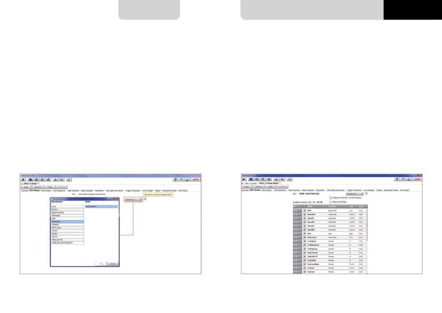
To load the ECU protocol in MX Strada series configuration:
n
enter “ECU Stream” tab
n
press Change ECU” button
n
select “ECU Manufacturer and “ECU Model” (in the example FORD/ MUSTANG 2010)
n
press OK
After setting the protocol the system comes back to “ECU Stream page and two checkbox ap-
pears:
n
“Enable the CAN Bus 120 Ohm Resistor (enabled by default; to be disabled in case MX
Strada series dash is additional to the vehicle one): the CAN bus needs two 120 Ohm
resistors at its two extremes. In case MX Series dash is the only device connected to
the ECU the 120 Ohm resistor should be enabled, else, very easily, it is already present
in the existing network and should be disabled;
n
silent on CAN Bus” (disabled by default) : usually the ECU expects an acknowledge
signal when transmits a message and, as default, the MX Strada series transmits this
signal Sometimes, particularly when there are other devices in the network, MX Strada
serie should not transmit it; in this case, enabling this flag, MX Strada series dash remains
completely silent.
MXG 1.2 MXP MXS 1.2 STRADA 2019.qxp_Layout 1 15/03/19 11:57 Pagina 25
MX STRADA SERIES
26 27
CHAPTER 5
This page works exactly like ECU Stream one. Here are additional CAN modules. To load one:
n
enter CAN2 Stream tab
n
press Change protocol” button
n
select “Manufacturer and “Model (in the example MEGALINE/PADDLESHIFT)
n
press OK
As for ECU Stream a PDF file with protocols updates history can be loaded clicking on the que-
stion mark as shown here below and the two checkbox appears as explained before.
5.2.3 CAN2 Stream configuration 5.2.4 CAN Expansions configuration
MX Strada series can be connected to various AiM CAN expansions:
n
LCU-One CAN
n
Channel Expansions
n
TC Hub
At the very first MX Strada series connection this page shows up:
Select the CAN expansion to set and press “OK”. Each expansion needs to be set filling in the
related panel.
MXG 1.2 MXP MXS 1.2 STRADA 2019.qxp_Layout 1 15/03/19 11:57 Pagina 27
28 29
MX STRADA SERIESCHAPTER 5
To set an LCU-One CAN:
n
press “New Expansion button;
n
select “LCU-One CAN” and press OK
n
name the LCU One and fill in its serial number or press “Get SN from a connected
expansion ” to receive the serial number from the connected LCU-One
n
select the multiplier to calculate AFR from lambda (in the example “14.57 Gasoline”) or add
a custom value pressing Add Custom Value (the related panel shows up)
n
set the LCU One channels double clicking on each channel and setting the panel that shows up
n
press Close” to save and exit
Please note: for any further information about AiM LCU-One CAN refer to the related user ma-
nual you find in the box or you can download from AiM website
www.aim-sportline.com documentation area, products section.
Please note: for any further information about AiM Channel expansion refer to the related user
manual you can download from AiM website
www.aim-sportline.com documentation area, products section.
Setting LCU-One CAN Setting Channel Expansion
To set a Channel Expansion:
n
press “New Expansion button;
n
select “Channel Expansion and press OK
n
name the Channel expansion and fill in its serial number or press Get SN from a connected
expansion to receive the serial number from the connected Channel Expansion
n
set each channel double clicking on each channel and setting the panel that shows up
(it works exactly like channels configuration – see the related paragraph)
n
press Close” to save and exit
MXG 1.2 MXP MXS 1.2 STRADA 2019.qxp_Layout 1 15/03/19 11:57 Pagina 29
30 31
MX STRADA SERIESCHAPTER 5
This CAN expansion only supports K type thermo-couples.
To set a TC Hub:
n
press “New Expansion button;
n
select TC Hub and press OK
n
name the TC Hub expansion and fill in its serial number or press Get SN from a
connected expansion to receive the serial number from the connected TC Hub
n
for each channel set sampling frequency, measure unit and display precision
n
press Close” to save and exit
Please note: for any further information about AiM TC Hub refer to the related user manual
you can download from AiM website
www.aim-sportline.com documentation area, products section.
Setting TC Hub.
5.2.5 Math channels configuration
To create math channels; available options are:
n
Bias: considering a relation between two mutually compatible channels it computes which
one is prevailing (typically used for suspensions or brakes);
n
Bias with threshold: it needs the user to set a threshold value for the considered channels ;
once these threshold are both exceeded the system makes the calculation;
n
Calculated gear: it calculates the gear position using engine RPM and vehicle speed
n
Precalculated gear: it calculates the gear position using Load/Shaft ratio for each gear
and for the vehicle axle too
n
Linear correction: typically used when a channel is not available in the desired format or
if it is wrongly tuned and cannot be tuned again
Each option asks the user to fill in a proper panel.
MXG 1.2 MXP MXS 1.2 STRADA 2019.qxp_Layout 1 15/03/19 11:57 Pagina 31
32 33
MX STRADA SERIESCHAPTER 5
Status Variables are internal math channels that can have only two different values: 1 (TRUE)
or 0 (FALSE). They may be useful for simplifying complex configurations, where it is required
to evaluate if to activate alarms, LEDs, Icons etc..
Let us explain with an example: we would like to turn ON a LED and an Icon when Water tem-
perature reaches 100°C and the RPM are higher than 2000. Instead of defining the same logic
for managing the icon and for managing the LED, we could define a Status Variable, Water
Temp Alarm and link Icon and LEDs to this variable. In this case we could define:
n
Water Temp Alarm is High when:
n
Water Temp is higher than 100°C and
n
RPM is greater than 2000.
And use Water Temp Alarm for managing Icons and LEDs.
As you may see, the Status Variables are more useful when the logic to be evaluated is complex
and involves different channels.
5.2.6 Status variables configuration
In order to define a Status Variable enter the proper TAB.
The Status variables can be used as any other channel, so they may be seen online, transmitted
to the CAN stream, recorded, used for triggering a command or for turning ON a LED or an
Icon. Mousing over the Status Variable a summary panel appears on the right as shown here
below.
MXG 1.2 MXP MXS 1.2 STRADA 2019.qxp_Layout 1 15/03/19 11:57 Pagina 33
34 35
MX STRADA SERIES
CHAPTER 5
To set the beacon.
Mousing over the question marks a pop up message explains the working mode of:
n
GPS Beacon (needs an optional GPS08 Module):
n
hold lap time for: the time period for which lap time is shown on your
MX Strada series display
n
the track width: width that will be considered for any GPS point you set
n
CAN Optical beacon (not recommended):
n
ignore additional lap signal for: after receiving an Infrared lap signal, the receiver
does not detect another signal for the time period fixed in the related box.
This is useful if more lap transmitters are placed nearby on the side of the track.
Needs an optional IR lap receiver to work.
5.2.7 Parameters configuration
MXG 1.2 MXP MXS 1.2 STRADA 2019.qxp_Layout 1 15/03/19 11:57 Pagina 35
36 37
MX STRADA SERIESCHAPTER 5
To set shift lights (on top) and alarm LEDs (bottom) of your MX Strada series. On top MX Strada series shift lights working mode can be set. Available options are:
n
shift lights, for helping in changing gear and
n
predictive time: for easily understanding if the current lap is faster or slower than the
reference lap.
Use as gear Shift Lights To use the led bar as shift lights click the icon ( ) for setting the
parameters. Configure:
n
at which RPM value the single LED turns ON
n
the sequence mode of the LEDs enabling the desired option:
n
a LED stays on if its threshold is exceeded
n
a LED stays on until another LED with higher threshold turns on or
n
link the shift lights to the engaged gear enabling the related checkbox;
5.2.8 Shift Lights and Alarms configuration
MXG 1.2 MXP MXS 1.2 STRADA 2019.qxp_Layout 1 15/03/19 11:57 Pagina 37
CHAPTER 5
38 39
MX STRADA SERIES
Use for predictive time.
Click the icon ( ) for setting the parameters.
In this case the LEDs colour are fixed in:
n
Green if the lap time is improving
n
Red if the lap time is worse than the reference lap
The threshold at which one LED is turned ON can be customized. Assuming “0.10 sec” is fixed
and the lap time is improving of 0.30 sec toward the reference lap, MX Strada series will switch
on 3 LEDs green; if, on the contrary, the lap time is worsening the LEDs will switch on red.
Please note: this option only works if an optional GPS Module is connected.
Create and set MX Strada series alarm
To create a new alarm press Add New Alarm” and the related panel shows up.
MXG 1.2 MXP MXS 1.2 STRADA 2019.qxp_Layout 1 15/03/19 11:57 Pagina 39
  • Page 1 1
  • Page 2 2
  • Page 3 3
  • Page 4 4
  • Page 5 5
  • Page 6 6
  • Page 7 7
  • Page 8 8
  • Page 9 9
  • Page 10 10
  • Page 11 11
  • Page 12 12
  • Page 13 13
  • Page 14 14
  • Page 15 15
  • Page 16 16
  • Page 17 17
  • Page 18 18
  • Page 19 19
  • Page 20 20
  • Page 21 21
  • Page 22 22
  • Page 23 23
  • Page 24 24
  • Page 25 25
  • Page 26 26
  • Page 27 27
  • Page 28 28
  • Page 29 29
  • Page 30 30
  • Page 31 31
  • Page 32 32
  • Page 33 33
  • Page 34 34
  • Page 35 35
  • Page 36 36
  • Page 37 37
  • Page 38 38
  • Page 39 39
  • Page 40 40
  • Page 41 41
  • Page 42 42
  • Page 43 43
  • Page 44 44
  • Page 45 45

Aim MXS 1.2 STRADA User guide

Type
User guide
This manual is also suitable for

Ask a question and I''ll find the answer in the document

Finding information in a document is now easier with AI