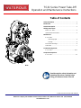
Waterous T-370, TC21 Operation and Maintenance Manual
- Type
- Operation and Maintenance Manual

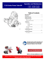
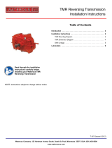
TC21 Series Power Take-Off
Operation and Maintenance Instructions
Read through the safety information and
operating instructions carefully before
using your Waterous Power Take-Off
F-1031, Section T-370 (Issued: 9/24/20)
Waterous Company, 125 Hardman Avenue South, South St. Paul, Minnesota 55075 USA (651) 450-5000
www.waterousco.com
Table of Contents
Safety Information .................................................................. 2
Introduction ............................................................................. 3
General Description ................................................................ 3
Shifting Instructions:
Main P.T.O. Shift ................................................................. 4
Optional Manual Override ................................................... 5
Maintenance:
P.T.O. Shift:
Indicating Lights ......................................................... 6
Linkage ....................................................................... 6
Tachometer Readings ......................................................... 6
Lubrication .......................................................................... 7
Troubleshooting Guide:
P.T.O. Shift .................................................................... 8-11
Component Inspection:
P.T.O. Shift ....................................................................... 12

T-370
Page 2 of 12
WARNING
Death or serious personal injury might occur if proper
operating procedures are not followed. The pump
operator, as well as individuals connecting supply or
discharge hoses to the apparatus must be familiar
with these pump operating instructions as well as
other operating instructions and manuals for the ap-
paratus, water hydraulics and component limitation.
WARNING
Unexpected Truck Movement
May result in serious personal injury or death
Failure to properly shift transmission in accordance to
the transmission operating instructions may result in
unexpected truck movement which may result in seri-
ous personal injury or death.
NOTICE
When towing, disconnect the drive shaft that con-
nects the pump transmission’s rear output (coupling)
shaft to the vehicles differential. Failure to do so may
result in damage from lack of lubrication.
WARNING
If the truck attempts to move, reduce engine speed to
idle. Put truck transmission in NEUTRAL and repeat
shifting instructions.
Safety Information
Read through and communicate safety information to the end user of this Waterous P.T.O.

T-370
Page 3 of 12
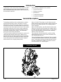
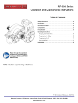
The Waterous TC21 Series Power Take-Off (PTO), with a
high-strength aluminum case, transmits power from the
truck’s automatic transmission either to the fire pump or to
the drive axle of the truck.
This instruction is divided into five sections:
• General Description
• Shifting Instructions
• Maintenance
• Troubleshooting Guide
• Component Inspection
The bearings and drive chain are lubricated by a splash
and passive lubrication system. Lubrication is accom-
plished when spray from the chain collects in a reservoir
in the top of the case. The lubricant flows out of the reser-
voir and onto the inside surface of the chain. This ensures
all pivoting components of the chain receive lubrication.
An electronic tachometer connection protrudes from the
tachometer housing at a 45° angle. This tachometer
pick-up senses the drive shaft speed.
The shift mechanism within the transmission consists of a
sliding internally-toothed collar which is always in en-
gagement with an externally-toothed section of the drive
shaft. A fork shifts the collar either to engage it with teeth
on the drive sprocket hub (PUMP/PTO) or to engage it
with the teeth on the coupling shaft (ROAD).
When in PUMP/PTO position, the shift collar transmits
power from the drive shaft through the drive sprocket and
the chain to the driven sprocket. The coupling shaft re-
mains stationary.
When in ROAD position, the shift collar transmits power
directly from the drive shaft through the coupling shaft to
the truck propeller shaft and drive axle(s). In this position,
the PTO drive and driven sprockets remain stationary
while the drive shaft rotates.
The pneumatic shift unit permits fast, positive shifting
without leaving the cab. A shift control, mounted in the
cab, activates the shift unit.
Three shift indicator lights are furnished. Two are mount-
ed in the cab and the other is mounted on the operator’s
panel. These lights indicate to the operator that the shift
has been completed into PUMP/PTO position and the
truck transmission is in pumping gear.
Introduction
General Description
TC21 Power Take-Off

T-370
Page 4 of 12
Main PTO Shift
Allison automatic transmissions are commonly used in fire
trucks, available with the shift patterns controlled both
electronically and hydraulically. This later type is common-
ly referred to as the ATEC transmission.
In the automatic transmission, certain sequences must
occur in proper order after the pump shift control is moved
to either PUMP or ROAD position.
Split shaft pump transmissions, automatic transmissions
and engines will vary in operation due to manufacturing
tolerances, lubrication temperature, etc. This variance in
each may or may not affect the ease of completing a full
shift into either PUMP or ROAD. Operator training and ex-
perience in shifting procedures is a requirement to becom-
ing skilled in a smooth, complete shift into either PUMP or
ROAD.
When the pump shift is activated, the operator may
hear a noise associated with the movement of the
shift unit. This does NOT mean that the shift has been
completed.
After the shift to pump operation is completed, the green
PUMP ENGAGED and OK TO PUMP lights in the cab
must be on before leaving the cab to operate the pump
from the operators panel. DO NOT LEAVE THE CAB IF
THE GREEN PUMP ENGAGED AND OK TO PUMP
LIGHTS ARE NOT ON.
Some truck builders may install a manual override for the
pump shift. The controls are normally installed from the
pump transmission to the operators panel.
WARNING
Unexpected Truck Movement. May result in seri-
ous personal injury or death.
Failure to properly shift transmission in accordance to
the transmission operating instructions may result in
unexpected truck movement which may result in se-
rious personal injury or death.
Shift to PUMP as follows:
1. Bring truck to complete stop.
2. Reduce engine to idle speed, put truck transmission
into NEUTRAL.
3. Set truck parking brake.
4. Move pump shift control to PUMP position.
NOTE: Green PUMP ENGAGED light may not illumi-
nate.
5. Shift truck transmission into pumping gear (DRIVE).
NOTICE
Shifting truck transmission into pumping gear
(DRIVE) above engine idle speed may cause dam-
age to the equipment.
6. Green PUMP ENGAGED and OK TO PUMP lights
should be on.
NOTICE
If green PUMP ENGAGED and OK TO PUMP light
are not on, momentarily shift truck transmission from
pumping gear (DRIVE) to NEUTRAL, then
REVERSE, then NEUTRAL, then back into pumping
gear (DRIVE). Lights should be on. If lights are not
on, repeat procedure.
7. Increase engine speed above idle and hold for a few
seconds. Watch speedometer to make sure it shows
some value of road speed.
NOTE: Some fire trucks have a speedometer that
will not show a value of road speed in a stationary
position.
WARNING
If the truck attempts to move, reduce engine speed to
idle. Put truck transmission in NEUTRAL and repeat
shifting instructions.
8. After leaving truck cab, block wheels using wheel
chocks.
9. To confirm that the pump is engaged:
• THROTTLE READY light on operator’s panel
is illuminated.
• Pump discharge pressure registers on gages.
• Other safety interlocks are activated.
Shift to ROAD as follows:
1. With engine speed at idle, put truck transmission in
NEUTRAL.
2. When speedometer slows to zero, move pump shift
control to ROAD position.
3. Engage truck transmission (DRIVE).
NOTICE
If you hear a loud grinding noise when you attempt to
move the truck, the shift to ROAD has not been com-
pleted. Shift into NEUTRAL, wait for grinding noise to
stop and re-engage truck transmission.
If grinding is a common occurrence after Step 3 is per-
formed, it may be prevented by shifting the truck trans-
mission into NEUTRAL, then to REVERSE, back to
NEUTRAL and finally to DRIVE.
4. After shifting the truck transmission to DRIVE, release the
parking brake and move the vehicle forward to confirm a
shift to ROAD has been completed.
Shifting Instructions

T-370
Page 5 of 12
Optional Manual Override
Split shaft pump transmissions, automatic transmissions
and engines will vary in operation due to manufacturing
tolerances, lubrication temperature, etc. This variance in
each may or may not affect the ease of completing a full
shift into either PUMP or ROAD. Operator training and
experience in shifting procedures is a requirement to
becoming skilled in a smooth, complete shift into either
PUMP or ROAD.
When the pump shift is activated, the operator may
hear a noise associated with the movement of the
shift unit. This does NOT mean that the shift has been
completed.
After the shift to pump operation is completed, the green
PUMP ENGAGED and OK TO PUMP lights in the cab
must be on before leaving the cab to operate the pump
from the operators panel. DO NOT LEAVE THE CAB IF
THE GREEN PUMP ENGAGED AND OK TO PUMP
LIGHTS ARE NOT ON.
If the vehicle builder has provided a means to manually
override the pneumatic pump shift, the override control
will be located at the operators panel or in the cab. The
override control will consist of a rod to the panel or a
cable or rod mechanism to the inside of the cab. The rod
or cable will be attached to the shift unit on the pump
transmission.
If the pump transmission is equipped with an over-
ride, shifting manually is done as follows:
It is recommended that this procedure be performed us-
ing two people; one person in the cab and one at the
override control position.
WARNING
Unexpected Truck Movement. May result in seri-
ous personal injury or death.
Failure to properly shift transmission in accordance to
the transmission operating instructions may result in
unexpected truck movement which may result in se-
rious personal injury or death.
Shift to PUMP as follows:
1. Bring truck to complete stop.
2. Reduce engine to idle speed, put truck transmission
in NEUTRAL.
3. Set truck parking brake.
4. Move in-cab pump shift control to CENTER position.
5. Move manual shift control to PUMP position.
6. Move the in-cab pump shift control into the PUMP
position.
7. Green PUMP ENGAGED light should be on.
NOTICE
If green PUMP ENGAGED light is not on, momentari-
ly shift truck transmission into REVERSE while keep-
ing pressure on the manual shift rod. Return to
NEUTRAL. Green PUMP ENGAGED light should be
on.
8. Shift truck transmission into pumping gear (DRIVE).
NOTICE
Shifting truck transmission into pumping gear above
engine idle speed may cause damage to the equip-
ment.
9. Green OK TO PUMP light should be on.
10. Increase engine speed above idle and hold for a few
seconds. Watch speedometer to make sure it shows
some value of road speed.
NOTE: Some fire trucks have a speedometer that will
not show a value of road speed in a stationary posi-
tion.
WARNING
If the truck attempts to move, reduce engine speed to
idle. Put truck transmission in NEUTRAL and repeat
shifting instructions.
11. After leaving truck cab, block wheels using wheel
chocks.
12. To confirm that the pump is engaged:
• THROTTLE READY light on operator’s panel
is illuminated.
• Pump discharge pressure registers on gages.
• Other safety interlocks are activated.
Shift to ROAD as follows:
1. With engine at idle speed, put truck transmission in
NEUTRAL.
2. When speedometer drops to zero, move in-cab pump
shift control into the CENTER position.
3. Move manual shift control to ROAD position.
4. Move the in-cab pump shift control into the ROAD
position.
5. Engage truck transmission (DRIVE).
NOTICE
If you hear a loud grinding noise when you attempt to
move the truck, the shift to ROAD has not been com-
pleted. Shift into NEUTRAL, wait for grinding noise to
stop and re-engage truck transmission, while keeping
pressure on the manual shift control rod.
1. After shifting the truck transmission to DRIVE, release
the parking brake and move the vehicle forward to
confirm a shift to ROAD has been completed.
Shifting Instructions

T-370
Page 6 of 12
PTO Shift:
Indicating Lights Operation
Check the operation of the pump shift indicating lights at
least weekly as follows:
NOTE: Block wheels with wheel chocks before begin-
ning.
1. With the pump in the ROAD position, truck transmis-
sion in NEUTRAL and the parking brake engaged,
ensure that the PUMP ENGAGED and OK TO PUMP
lights in the cab are off.
2. Shift to PUMP following the shifting instructions sec-
tion of this document.
a) Ensure that the green PUMP ENGAGED and OK
TO PUMP lights in the cab are on.
b) Ensure that the green THROTTLE READY light
on the operator’s panel is on.
3. Apply the service (foot) brake and release the parking
brake.
a) Ensure that the green OK TO PUMP light in the
cab is off.
b) Ensure that the green THROTTLE READY light
on the operator’s panel is off.
4. Engage the parking brake and shift truck transmission
to NEUTRAL.
a) Ensure that the green OK TO PUMP light in the
cab is off (automatic truck transmission only).
5. Shift to ROAD following the shifting instructions sec-
tion of this document.
a) Ensure that the green PUMP ENGAGED and OK
TO PUMP lights in the cab are off.
b) Ensure that the green THROTTLE READY light
on the operator’s panel is off.
Linkage
Periodically check all shift linkage for freedom of move-
ment. Clean and lubricate as necessary.
Tachometer Readings:
The pulse generator generates a frequency proportional
to the speed of the rotating shaft. The frequency reading
from the sensor is to be used to calculate the rotational
speed of the shaft as follows:
Multiply the frequency (Hz) reading from the tachometer
sensor by ten to obtain shaft revolutions per minute (rpm).
Hz x 10 = RPM
Maintenance

T-370
Page 7 of 12
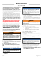
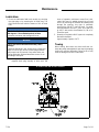
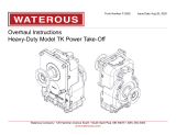
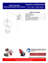
Lubrication:
1. Check the lubrication fluid level monthly by checking
the sight plug or by removing the oil level plug. The
fluid should be level with the bottom of the oil level
hole.
NOTICE
Lubrication fluid temperature should not exceed
250 degrees F for extended periods of time.
Premature seal wear and damage will occur.
NOTICE
Low or excessive lubrication fluid may cause
damage.
If lubricant fluid level is low, locate source of leak and
repair. If level is high, loosen oil level plug and drain
until proper level is reached. If any water drains out,
change lubrication fluid and determine source of wa-
ter leakage and repair.
2. Change lubrication fluid and clean breather and
magnetic drain plug annually or after each 100
hours of operation, whichever comes first. Lubri-
cation fluid may be added through the oil level
hole or by removing the breather and adding fluid
through the opening. Any type of automatic
transmission fluid (ATF) may be used. For ambi-
ent temperatures over 90 F, SAE 20 oil 300 SSU
@ 100 F with service classification SA, SB or SC
should be used.
3. Quantity of lubrication fluid if system is completely
drained and refilled:
Approximately 6 quarts of ATF.
Towing
When towing, disconnect the drive shaft that con-
nects the pump transmission’s rear output (coupling)
shaft to the vehicles differential. Failure to do so may
result in damage from lack of lubrication.
Maintenance
TC 21 Oil Level and Oil Fill Locations

T-370
Page 8 of 12
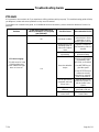
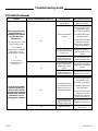
PTO Shift
It is important to know what to do if you experience shifting problems with your pump. This troubleshooting guide will help
you diagnose, isolate and correct problems as they are encountered.
For problems not covered in this guide, or for additional technical assistance, please contact the Waterous Service De-
partment.
Problem
Is the chassis transmission in
DRIVE (automatic) or in its pump
gear (Manual)?
Possible Cause
Recommended Action
PTO won’t engage
PTO shift control is in the
PUMP position and
PUMP ENGAGED light
does not come on.
No
Butt-tooth condition
Place the chassis
transmission in Drive
(automatic) or in its
pumping gear (manual).
Yes
Malfunctioning shift
indicating switch or
switch out of adjust-
ment
Replace or adjust the
shift indicating switch or
bracket.
Manual override link-
age binding
Repair or replace to
eliminate binding.
Excessive driveline
torque
Shift the chassis trans-
mission into REVERSE
momentarily, then
NEUTRAL, then DRIVE.
----------
Consider reducing en-
gine idle speed.
----------
It may be necessary to
contact the chassis
transmission manufac-
turer for assistance.
Low air pressure to
pneumatic shift unit
(80 psi min.)
Allow air pressure to
build in the system, re-
pair any leaks in the
system.
Leaking pneumatic
shift unit.
Repair or replace
pneumatic shift unit.
Malfunctioning air
control valve
Repair or replace air
control valve.
Troubleshooting Guide

T-370
Page 9 of 12
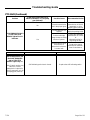
PTO Shift (Continued)
Problem
Is the PUMP ENGAGED light on?
Possible Cause
Recommended Action
PTO output will not en-
gage and there is a
grinding noise emanat-
ing from the pump
transmission.
PTO shift control is in the
PUMP position and:
1. The chassis
transmission is in DRIVE
(automatic) or in its
pumping gear (manual).
or
2. The chassis
transmission is in
NEUTRAL.
No
Manual override link-
age binding.
Repair or replace to
eliminate binding.
Excessive driveline
torque.
Shift the chassis trans-
mission into REVERSE
momentarily, then
NEUTRAL, then DRIVE.
----------
Consider reducing en-
gine idle speed.
----------
It may be necessary to
contact the chassis
transmission manufac-
turer for assistance.
Low or no air pressure
to pneumatic shift unit
(80 psi min.)
Allow air pressure to
build in the system, re-
pair any leaks in the
system.
Damage to internal
pump transmission
shifting components.
See pump transmission
inspection instructions.
Yes
Shift indicating switch
is out of adjustment or
its bracket is dam-
aged.
Adjust the shift indicat-
ing switch or replace the
bracket.
Damage to internal
pump transmission
shifting components.
See pump transmission
inspection instructions.
Chassis engine stalls
after placing the PTO
shift control in PUMP
and placing the chassis
transmission in DRIVE
(automatic) or in its
pumping gear (manual).
No
Pump transmission
has not shifted out of
ROAD due to exces-
sive driveline torque.
Shift the chassis trans-
mission into REVERSE
momentarily, then
NEUTRAL, then DRIVE.
----------
Consider reducing en-
gine idle speed.
----------
It may be necessary to
contact the chassis
transmission manufac-
turer for assistance.
Damage to internal
pump transmission
shifting components.
See pump transmission
inspection instructions.
Yes
Seized fire pump.
Repair fire pump as
necessary.
Troubleshooting Guide

T-370
Page 10 of 12
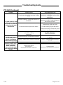
PTO Shift (Continued)
Problem
Is the chassis transmission in
DRIVE (automatic) or in its pump
gear (Manual)?
Possible Cause
Recommended Action
PUMP ENGAGED light is
on but THROTTLE
READY light will not il-
luminate.
No
Chassis transmission
not in the proper gear.
Place the chassis
transmission in DRIVE
(automatic) or in its
pumping gear (manual).
Yes
Parking brake is not
applied.
Apply the parking brake.
Problem with high
range lockup or safety
interlock systems.
Contact the apparatus
manufacturer or consid-
er
alternative wiring for
high range lockup.
Problem with chassis
transmission or
transmission electron-
ic control unit.
Contact the chassis
transmission manufac-
turer for assistance.
Problem
Possible Cause
Recommended Action
PTO shift control is in
the ROAD position, but
the PUMP ENGAGED
and/or THROTTLE
READY lights stay on.
Note: Chassis engine may
stall if the chassis
transmission is placed in
DRIVE (automatic) or in its
pumping gear (manual).
Shift indicating switch stuck closed.
Replace the shift indicating switch.
Troubleshooting Guide

T-370
Page 11 of 12
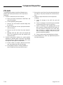
PTO Shift (Continued)
Problem
Possible Cause
Recommended Action
PTO shift control is in the
ROAD position and grind-
ing sounds are heard em-
anating from the pump
transmission.
Chassis transmission is in gear when shifting
pump.
Place the chassis
transmission in NEUTRAL before shifting
pump
transmission.
Butt-tooth condition - chassis transmission is in
REVERSE.
Place the chassis
transmission in DRIVE after shifting pump
transmission to ROAD.
Excessive driveline torque and/or rotation.
Ensure the driveline is not
rotating before shifting to ROAD.
----------
Consider reducing engine idle speed.
----------
It may be necessary to contact the chassis
transmission manufacturer for assistance.
Damage to pump
transmission shifting
components.
See pump transmission
inspection instructions.
Manual PTO shift
override control cannot
be moved by hand
(electric or pneumatic
shift functions properly).
Air pressure present on pneumatic shift piston.
Place the shift air control valve in the cen-
ter position.
Binding or malfunctioning manual shift linkage.
Repair or replace to eliminate linkage
binding.
The chassis engine stalls
when the chassis trans-
mission is placed in
DRIVE (automatic)
after moving the pump
shift control to the ROAD
position.
Shift indicating switch stuck closed.
Replace the shift indicating switch.
Problem with chassis
transmission or
transmission electronic control unit.
Contact chassis
transmission manufacturer for assistance.
Troubleshooting Guide

T-370
Page 12 of 12
PTO Shift:
The following procedures should be followed when a
problem with a pump transmission shift component is
suspected.
1. Perform a shift force test on the shift unit.
a) Place the chassis transmission in NEUTRAL and
shut off the engine.
b) Set the apparatus parking brake.
c) Remove any shift manual override linkage from
the shift unit.
d) Drain the lubricant from the pump transmission.
(Also see step 2).
e) Remove the shift unit from the pump transmis-
sion.
f) Manually slide the shift unit’s rod forward and
back. Force required to move rod should not be
more than 35 lbs.
2. Examine transmission lubricant for metal particles
appearing in quantity and/or size which may indicate
excessive wear to internal components. Also check
the magnetic drain plug for metal particles.
a) If there is little or no debris, refill with clean lubri-
cant, reassemble the shift unit and retest.
b) If the problem persists or if large quantities or
sizes of debris are found, proceed to step 3.
3. Remove the case oil pan from the pump transmission
according to the pump transmission overhaul instruc-
tions.
4. Inspect the pump transmission shift components
including:
a) Check for damage to the shift fork and shift
shoes.
b) Check for damage to the shift fork pivot shoulder
screw and the clevis end on the shift unit.
c) Check for damage to the engaging teeth on the
drive sprocket, coupling shaft and shift collar. Mi-
nor burrs found on the teeth of the shift collar,
drive sprocket or coupling shaft may be filed
clean. If excessive damage is found on any com-
ponent it should be replaced.
d) Check to make sure that all bearings turn freely.
5. Contact Waterous to order any replacement parts or
for further assistance.
Component Inspection
-
 1
1
-
 2
2
-
 3
3
-
 4
4
-
 5
5
-
 6
6
-
 7
7
-
 8
8
-
 9
9
-
 10
10
-
 11
11
-
 12
12


Waterous T-370, TC21 Operation and Maintenance Manual
- Type
- Operation and Maintenance Manual
Ask a question and I''ll find the answer in the document
Finding information in a document is now easier with AI
Related papers
-
 Waterous T-364 Operation and Maintenance Manual
-
 Waterous SEC. 2441, C21 Operation and Maintenance Manual
-
 Waterous F-3009 Operation and Maintenance Manual
-
 Waterous F-2873, K SERIES Operation and Maintenance Manual
-
 Waterous F-2587 Operating instructions
-
 Waterous F-2902 HEAVY DUTY ALUMINUM TK Operating instructions
-
 Waterous SEC. 3043, RF600 Installation guide
-
 Waterous T-367 Installation guide
-
 Waterous SEC. 2125, RF600 Operation and Maintenance Manual
-
 Waterous SEC. 2308-1, CABLE Operation and Maintenance Manual


