Page is loading ...

VMAC – Vehicle Mounted Air Compressors
Toll Free: 1-800-738-8622 Local: 1-250-740-3200
Fax: 1-250-740-3201
1
Installation Instructions for the
A700184 – 24V to 12V Power Converter
Operation
The 24V to 12V Power Converter kit allows a 24 volt DC source to run a 12 volt
DC component that requires a maximum of 40 Amps. Whenever powered, the
power converter’s 12 volt DC output will be enabled.
This kit’s power converter should be installed in a location where it is ventilated
and protected from water/splash, i.e. in cab of vehicle.
Important Information
The information in this manual is intended for certified VMAC installers who have
been trained in installation procedures and for people with mechanical trade
certification who have the tools and equipment to properly and safely perform the
installation. Do not attempt this installation if you do not have the appropriate
mechanical training, knowledge and experience.
Follow all safety precautions for mechanical work. If you have difficulty with the
installation, contact VMAC.
To order parts, contact your VMAC dealer. Your dealer will ask for the VMAC
serial number, part number, description and quantity. To locate your nearest
dealer, call 1-800-738-8622.
Notice: Manuals and products are subject to change without notice
Document #1900958
Version
Revision Details
Revised by/date
Approved
Implemented
A
ECN-12-189
OJ 30 Jan 2013
SM/RD 30 Jan 2013
05 Feb 2012
Copyright 2012
All trademarks used in this manual are the property of the respective copyright holder.
The contents of this manual may not be reproduced in any form without the express written permission of VMAC, 1333
Kipp Road, Nanaimo, BC V9X 1R3. Printed in Canada

VMAC – Vehicle Mounted Air Compressors
Toll Free: 1-800-738-8622 Local: 1-250-740-3200
Fax: 1-250-740-3201
2
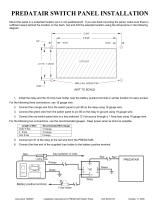
Installing the Power Converter for the Predatair
Ground
RED - 12V
INPUT
POWER CONVERTER
OUTPUT
PREDATAIR
Key Switched
24V Power Source
GREEN - GND
20A Fuse
C B A
Figure 1 – Installing the power converter
1. Disconnect the battery/power source.
2. Find a suitable location to install the power converter where it is protected from
the elements. Ensure it’s a ventilated area to prevent the unit from
overheating.
3. Measure the total length of wires that will be required to go from the power
source to the power converter to the Predatair. Measure both the power and
ground wire lengths, add them together, and select the correct wire size from
Table 1.
Total length of Power wire PLUS Ground wire
Recommended Wire Gauge
Less than 5 ft.
12AWG
5 ft. to 8 ft.
10AWG
More than 8 ft.
8AWG
Table 1 - Wire guage size
4. Run wires of recommended gauge from the power source to the power converter.
5. Ensure the 24V power source is fused or place an inline 20A ATC/ATO fuse as
close as possible to the battery/power source.
Note: Any length of wire unprotected by a fuse is a potential fire
hazard.
6. Attach wires coming from the power source to the Input and Ground terminals using
the unit’s set screws. Use Loctite 425 and fasten firmly, but do not over-tighten set
screws.
7. Using wire size based on Table 1, extend the Predatair interface cable’s RED and
GREEN wires to the power converter.

VMAC – Vehicle Mounted Air Compressors
Toll Free: 1-800-738-8622 Local: 1-250-740-3200
Fax: 1-250-740-3201
3
8. Attach the extended interface cables to the Output and Ground terminals using the
unit’s set screws. The RED wire (Pin C on connector) goes to the Output, and
GREEN wire (Pin B on connector) goes to the Ground. Use Loctite 425 and fasten
firmly, but do not over-tighten set screws.
9. Test the power converter as described below before connecting the interface cable
to its mating connector on the Predatair.
Testing the Power Converter with the Predatair
1. Verify power converter wiring.
2. Re-attach battery/power source and verify voltage polarity on the interface cable
connector with a multi-meter. RED/Pin C (+) to GREEN/Pin B (-) should be nominal
12V.
3. Connect the interface cable connector to its mating connecting on the Predatair.
4. The Predatair display screen will power on and perform SYSTEM CHECK followed
by SYSTEM READY. The warning light on the display box should not be illuminated.
Note: Perform pre-operation checklist tasks. See Predatair Installation
Manual for details on installation requirements, hydraulic system
requirements, and pre-operation checklist tasks.
5. Enable PTO/hydraulic system. When temperatures are below -15°C, circulate the
hydraulic fluid to warm it before activating the PREDATAIR.
6. Press the ON button. The Ready light should be illuminated. The warning light on
the display box should not be illuminated.
7. Operate the system with an air tool for at least ½ hour. Ensure the Predatair fan
powers on during the test.
Note: The fan powers on when compressor temperature rises above 88°C. It
also powers on if hydraulic and compressor temperatures are both above
66°C and 77°C, respectively.
8. For the duration of the test, the Predatair should remain powered and the display
box screen show text. (i.e. Predatair should not turn off by itself, nor should the
display box screen go blank when the fan starts/turns-on.)
9. Press OFF on the Predatair’s display box.
Review the Predatair Owners Manual before using the Predatair.
/