Novus TxIsoRail-HRT User manual

Type
User manual

Novus TxIsoRail-HRT is a configurable temperature transmitter designed for industrial applications. It offers versatile input options for RTDs, thermocouples, and mV signals, providing accurate temperature measurement and conversion to a 4-20 mA output. With HART communication support, it enables remote monitoring and configuration. The TxIsoRail-HRT ensures reliable performance with electrical isolation between input and output, internal polarity inversion protection, and a robust housing for harsh environments.

Novus TxIsoRail-HRT is a configurable temperature transmitter designed for industrial applications. It offers versatile input options for RTDs, thermocouples, and mV signals, providing accurate temperature measurement and conversion to a 4-20 mA output. With HART communication support, it enables remote monitoring and configuration. The TxIsoRail-HRT ensures reliable performance with electrical isolation between input and output, internal polarity inversion protection, and a robust housing for harsh environments.

NOVUS AUTOMATION 1/4
TxIsoRail
-HRT
TEMPERATURE TRANSMITTER
- OPERATING MANUAL – V1.1x E
INTRODUCTION
The TxIsoRail-HRT is a configurable DIN rail mount temperature
transmitter widely required in various industrial processes. Its
universal input can be configured to read RTDs, thermocouples and
mV signals.
It converts the input signal into a 4-20 mA linear output proportional
to the configured range. The TxIsoRail-HRT uses the HAR
communication protocol over the 4-20 mA output current loop.
The input and output are electrically isolated, enhancing their
performance and user and system safety.
SPECIFICATIONS
Sensor input: User defined. The supported sensors are listed in
Table 1, along with their maximum measurement and minimum
retransmission ranges.
Thermocouples: Types J, K, R, S, T, N, E and B according to
IEC 60584 (ITS-90).
Impedance >> 1 M
Pt100: Excitation 0.15 mA, α= 0.00385, according IEC 60751
(ITS-90).
Pt1000: Excitation 0.20 mA, α= 0.00385, according IEC 60751
(ITS-90).
NTC R25: 10 k ±1 %, β25/85 = 3435
Voltage: 0 to 50 mVdc. Impedance >> 1 M
Sensor Type
Maximum Measurement
Range
Minimum
Retransmission Range
Thermocouple K
-150 to 1370 °C
(-238 to 2498 °F)
50 °C
(90 °F)
Thermocouple J
-100 to 760 °C
(-148 to 1400 °F)
50 °C
(90 °F)
Thermocouple R
-50 to 1760 °C
(-58 to 3200 °F)
200 °C
(360 °F)
Thermocouple S
-50 to 1760 °C
(-58 to 3200 °F)
200 °C
(360 °F)
Thermocouple T
-160 to 400 °C
(-256 to 752 °F)
50 °C
(90 °F)
Thermocouple N
-270 to 1300 °C
(-454 to 2372 °F)
50 °C
(90 °F)
Thermocouple E
-90 to 720 °C
(-130 to 1328 °F)
50 °C
(90 °F)
Thermocouple B
500 to 1820 °C
(932 to 3308 °F)
200 °C
(360 °F)
Pt100
-200 to 650 °C
(-328 to 1202 °F)
30 °C
(54 °F)
Pt1000
-200 to 650 °C
(-328 to 1202 °F)
30 °C
(54 °F)
NTC
-30 to 120 °C
(-22 to 248 °F)
10 °C
(18 °F)
Voltage 0 to 50 mV 3 mV
Table 1Sensors accepted by the transmitter
Switch-on delay: < 10 s with factory damping filter configured. The
accuracy is only guaranteed after 15 min.
Terms of reference: Ambient: 25 ° C (77 °F); voltage: 24 Vdc, load:
250 . 15 minutes required for stabilization time after configuration.
Temperature Effect:
NTC: < 0.11 % FS / 25 °C (77 °F)
Other sensors: < 0.05 % FS / 25 °C (77 °F)
(FS = Full Scale)
Response time: Typical 6 s using factory damping filter. This is the
maximum time between a temperature step being applied in the input
and the output reaching 90 % of the corresponding value.
HART Protocol Version: 7
RTD cable resistance effect: 0.005 °C /
Maximum allowable cable resistance for RTD: 25
Accuracy: Calibration error in relation to sensor measuring range.
Sensor Type
CURRENT LOOP
HART
Typical
Error
Maximum
Error
Maximum
Error
Pt100
(-200 to 650 °C)
0.08 % 0.15 % 0.05 % 0.15 %
Pt1000
(-200 to 650 °C)
0.07 % 0.15 % 0.04 % 0.15 %
K, J, R, S, T, N,
E, B
0.07 % (*) 0.15 % (*) 0.04 % (*) 0.15 % (*)
mV
0.07 %
0.15 %
0.15 %
NTC
0.20 °C
(0.36 °F)
0.45 °C
(0.81 °F)
0.45 °C
(0.81 °F)
Table 2Input accuracy
(*) Add cold junction compensation: < ± 1 °C (1.8 °F).
Power supply influence: < 0.005 % / V typical (percentage of the
full measure range).
Output (4-20 mA): 4-20 mA current, 2-wires; and proportional to the
configured range.
Output Resolution (4-20 mA): 0.25 µA
Power supply: 8.5 to 36 Vdc (output 4-20 mA)
Maximum load (RL): RL (max.) = (Vdc – 8.5) / 0.0215 []
Where: Vdc = Power supply voltage (8.5 to 36
Vdc)
Operating Temperature: -40 to 85 °C (-40 to 185 °F)
Humidity: 0 to 90 % RH
It features electrical isolation between input and output: 1.5 kVrms
Internal protection against polarity inversion.
Cold junction compensation for thermocouples.
Connection Wire Cross Section: 0.14 to 1.5 mm²
Screw Tightening: 0.8 Nm
Housing: ABS UL94-HB
Protection: IP20
Standards and Certifications: NAMUR NE-43 standard and CE,
UKCA and HART® certifications.
TxIsoRail-HRT
NOVUS AUTOMATION 2/4
CONFIGURATION
When the transmitter is used with the factory setting, no further
action is required and the transmitter is ready to be installed.
Changes to the configuration are possible through the TxConfig II
software, provided free of charge.
The TxConfig II configuration software allows the device configuration.
A TxConfig-HRT interface is required to allow the communication
between a computer and the device. The Txconfig II configuration
software is continuously updated and new versions can be downloaded
at no charge from the manufacturer’s website. To install, execute the
TxConfigIISetup.exe file and follow the instructions.
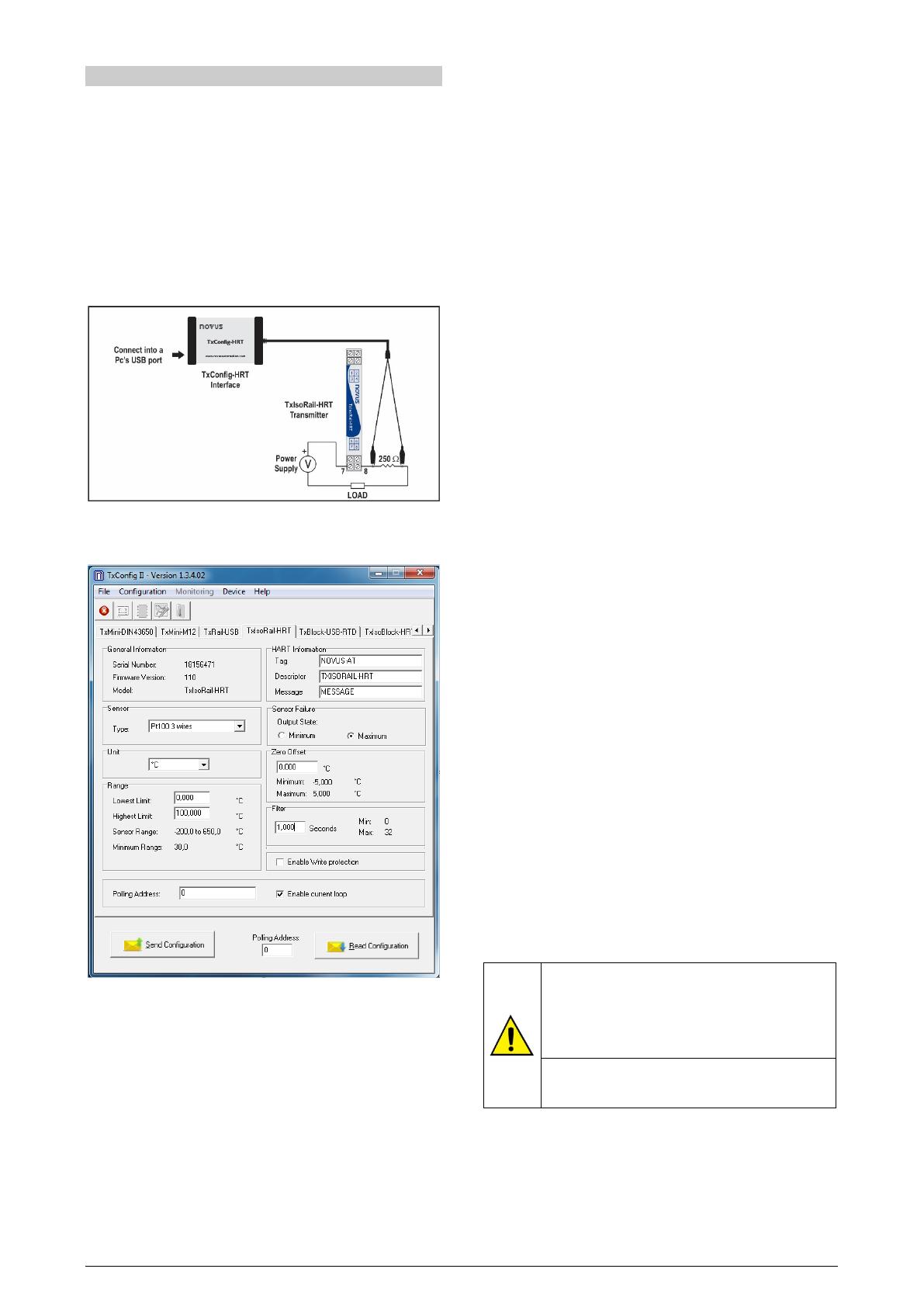
The interface connects the transmitter to the computer, as shown in
Fig. 1:
Fig. 1TxConfig-HRT interface connection to the TxIsoRail-HRT
SOFTWARE CONFIGURATION:
Fig. 2TxConfig II software main screen
The fields in the screen mean:
1. General Information: This field shows information that identifies
the transmitter. This information should be sent to the
manufacturer in an eventual request for technical assistance.
2. Sensor: Select the type of sensor to be used. See Table 1.
3. Unit: Select the temperature unit to °C (Celsius) or °F
(Fahrenheit).
4. Range: Sets de measurement range of the transmitter.
Lowest Limit: Equivalent temperature for a current of 4 mA.
Highest Limit: Equivalent temperature for a current of 20 mA.
Sensor Range
The values chosen cannot exceed the Range of Sensor shown
in this field. See Table 1 of this manual.
Minimum Range
Do not set a lower band (span) that the Minimum Range
indicated below in this same field. See Table 1 of this manual.
5. HART Information:
Tag: Field with a brief identification of the equipment (up to 8
characters);
Descriptor: Descriptor used by the master to register the data
(up to 16 characters);
Message: Message used by the master for registering (up to 32
characters);
6. Sensor Failure: It establishes the output behavior, when the
transmitter indicates a failure:
Minimum: Output current goes to < 3.6 mA (down-scale),
typically used for refrigeration.
Maximum: Output current goes to > 21.5 mA (up-scale), typically
used for heating.
7. Zero Offset: It corrects small deviations presented in the
transmitter output, for example, when the sensor is replaced.
8. Filter: Damping filter.
The damping filter changes the response time of the transmitter in
order to smooth the variations in the output. The value set in the
filter indicates the time interval at which the PV will reach 63 % of
its final value.
The factory setting is 1.0 s, and can be changed from 0 s to 32 s.
For example, in the case where the temperature should range
from 0 ° C to 100 ° C, if you considering the factory settings, after
1.0 s the temperature value shall be equal to 63 °C. A zero value
disables this function.
9. Enable Write protection: When activated, configuration is not
allowed.
10. Send Configuration: It applies the new setup. Once sent, the
setup will be immediately applied on the transmitter.
11. Read Configuration: Reads the current configuration in the
transmitter connected. The screen now presents the current setup
that may be changed by the user.
12. Polling Address: Dynamic (i.e., configurable) address that allows
devices to be quickly identified on a network.
13. Enable Current Loop: When disabled, the current remains at 4
mA.
FACTORY SETTINGS
Sensor: Pt100 3-wire, range 0 to 100 °C
Sensor failure: Upscale (maximum)
0 °C zero correction
Unit: °C
Filter: 1.0 s
Address: 0
Current Loop: Enabled
It is possible to configure the device through a third party
software and with the help of an FSK modem to perform
HART® communication.
An EDD (Electronic Device Descriptor) file is available,
which can be used with
compatible systems and allows
access to the settings and supervise the transmitter.
To put the devices on the same network (or put them in
multidrop mode), they must have different polling
addresses and the current loop must be disabled.
TxIsoRail-HRT
NOVUS AUTOMATION 3/4
Fig. 3Handheld terminal connection
MECHANICAL INSTALLATION
The TxIsoRail-HRT transmitter is suitable to be installed in 35 mm
DIN rail. Vibrations, moisture and extreme temperatures, electro-
magnetic interference, high voltage and other interferences can
permanently damage the unit, and could cause error in the measured
value.
DIMENSIONS
Fig. 4Transmitter dimensions
ELECTRICAL INSTALLATION
The Fig. 5 shows the electrical connections required. The
TxIsoRail-HRT wiring for thermocouple, RTD, resistance and
voltage are done according to the Fig. 4.
Fig. 5TxIsoRail-HRT transmitter electrical connections
LOAD represents the 4-20 mA current measuring device (indicator,
controller, register, etc.).
Polyamide enclosure.
Section of the cable used: 0.14 to 1.5 mm ².
Recommended torque in the terminal: 0.8 Nm.
RECOMMENDATIONS FOR INSTALLATION
Conductors of small electrical signals must be distant from
activation or high-tension/current conductors, preferably passing
through grounded conduits.
A specific electrical power supply network should be provided for
instruments use only.
In controlling and monitoring applications, possible consequences
of any system failure must be considered in advance.
RC filters (47 and 100 nF) in inductor charges (contactors,
solenoids, etc.) are recommended.
ELECTRICAL CONNECTIONS
The figures below show the electrical connections required. The
terminals 1, 2, 3 and 4 are dedicated to the sensor connection.
LOAD represents the 4-20 mA current measuring device (indicator,
controller, recorder, etc.).
Pt100 2-WIRE
Note: When the Pt100 2-wire the terminals 1 and 3 must be
interconnected, according to the figure below.
To use the Pt100 2-wire, you must configure the Pt100 3-wire option
in TxConfig II.
The Pt100 wire length should be less than 30 cm to maintain the
measurement error within specifications (electrical resistance).
Fig. 6Transmitter electrical connections (Pt100 2-wire)
Pt100 3-WIRE
Fig. 7Transmitter electrical connections (Pt100 3-wire)
Pt100 4-WIRE
Fig. 8Transmitter electrical connections (Pt100 4-wire)
TxIsoRail-HRT
NOVUS AUTOMATION 4/4
Pt100 3 and 4-wire / Pt1000 3 and 4-wire: The use of wires with same
length and gauge is recommended for a better resistance
compensation. The transmitter compensates up to 25 ohm per wire.
THERMOCOUPLES
Fig. 9Transmitter electrical connections (Thermocouple)
VOLTAGE (0-50 mV)
Fig. 10Transmitter electrical connections (0-50 mV)
NTC
Fig. 11Transmitter electrical connections (NTC)
OUTPUT (4-20 mA)
Fig. 12Transmitter electrical connections (4-20 mA)
OPERATION
The transmitter is factory calibrated with standardized sensors, not
requiring any adjustment by the user.
Fine corrections can be accomplished through the TxConfig II
software (in units of temperature).
The user may choose the sensor and the span that best fits its
application. The sensor span must lie within the range specified for
the selected sensor.
It is important to note that the accuracy of the transmitter refers to the
maximum range of the sensor used, regardless of the actual span.
Example:
The sensor Pt100 has a maximum range of -200 to 650 °C and
typical accuracy 0.08 %.
Thus, we can have a typical error up to 0.68 °C (0.08 % of 850 °C).
This error is the same, no matter if total span is used (-200 to 650
°C) or a narrower user-defined span is used, like 0 to 100 °C.
WARRANTY
Warranty conditions are available on our website
www.novusautomation.com/warranty.
  • Page 1 1
  • Page 2 2
  • Page 3 3
  • Page 4 4

Novus TxIsoRail-HRT User manual

Type
User manual

Novus TxIsoRail-HRT is a configurable temperature transmitter designed for industrial applications. It offers versatile input options for RTDs, thermocouples, and mV signals, providing accurate temperature measurement and conversion to a 4-20 mA output. With HART communication support, it enables remote monitoring and configuration. The TxIsoRail-HRT ensures reliable performance with electrical isolation between input and output, internal polarity inversion protection, and a robust housing for harsh environments.

Ask a question and I''ll find the answer in the document

Finding information in a document is now easier with AI