Page is loading ...

Owner'sManual/Manualdelpropietario
CRRFTSMRN°
GARAGEDOOROPENER
ABRIDORDEPUERTADE COCHERA
ForResidentialUse0nly/S61oparausoresidencial
Model/Modelo139.53939D
I"11
z
I"11
"o
;z=,
z_
Readandfollowall safetyrulesandoperating
instructionsbeforefirstuseofthis product.
Fastenthe manualnearthegaragedoorafter
installation.
Periodic checksof theopener arerequiredto
ensuresafeoperation.
Leery seguirtodaslas reglasdeseguridady
lasinstruccionesdeoperaci6n antesde usar
esteproductoporprimeravez.
Guardarestemanualcercade la puerta de la
cochera.
Sedebenrealizarrevisionesperi6dicas
del abridorde puertas para asegurarsu
operaci6n segura.
c_us
Sears, Roebuck and Co., Hoffman Estates, IL 60179 U.S.A
www.sears.com/craftsman

TABLE OF CONTENTS
Introduction 2-7
Safetysymbol reviewandsignal word review................ 2
Preparingyour garagedoor ............................. 3
Tools needed......................................... 3
Planning .......................................... 4-5
Carton inventory ...................................... 6
Hardware inventory.................................... 7
Assembly 8-11
Assemblethe rail and install thetrolley ..................... 8
Fastenthe rail to the motor unit .......................... 9
Install the idler pulley .................................. 9
Install the belt ....................................... 10
Tighten the belt...................................... 10
Install the sprocket cover .............................. 11
Installation 11-26
Installation safety instructions .......................... 11
Determinethe headerbracket location .................... 12
Install the header bracket .............................. 13
Attachthe rail to the headerbracket ...................... 14
Position theopener................................... 15
Hangthe opener ..................................... 16
Install the door control ................................ 17
Install the battery .................................... 18
Install the lights ..................................... 18
Attachthe emergency releaseropeand handle.............. 19
Electrical requirements................................ 19
Install The Protector System®........................ 20-22
Fastenthe door bracket............................. 23-24
Connectthedoor arm to the trolley ................... 25-26
Adjustment 27-29
Program thetravel limits............................... 27
Setting the force ..................................... 28
Testthe safety reversalsystem.......................... 29
TestThe ProtectorSystem® ............................ 29
Operation 30-36
Operationsafety instructions ........................... 30
Using your garagedoor opener ......................... 30
Using the wall-mounted door control ..................... 31
Careof your opener .................................. 32
Toopen the door manually ............................. 32
Batterybackup ...................................... 33
Having a problem (Troubleshooting) ..................... 34
Diagnostic chart ..................................... 35
Smart Control Paner messages ......................... 36
Programming 37
Toadd or reprograma hand-held remote control ............ 37
Toeraseall codesfrom motor unit memory................ 37
3-Function remotes................................... 37
Repair Parts 38-39
Rail assemblyparts................................... 38
Installation parts ..................................... 38
Motor unit assembly parts ............................. 39
Accessories 40
Warranty 40
Notes 41
Repair Parts & Service Back Cover
INTRODUCTION
SafetySymbolReview andSignal WordReview
This garage door opener has beendesignedand tested to offer safe serviceprovided it is installed, operated,maintained and tested in
strict accordancewith the instructions and warnings contained in this manual.
Mechanical
Electrical
Whenyou seethese SafetySymbols and Signal Words on the
following pages,they will alert you to the possibility of serious
injuryor deathif you do not comply with the warnings that
accompany them, The hazardmay come from something
mechanicalor from electric shock. Readthe warnings carefully.
Whenyou seethis Signal Word on the following pages,it will alert
you to the possibility of damageto your garage door and/or the
garage door opener if you do not comply with the cautionary
statements that accompany it. Readthem carefully.

Preparingyourgaragedoor
Beforeyou begin:
• Disable locks.
• Removeany ropes connectedto garagedoor.
• Completethefollowingtestto makesureyour garage door is
balancedand is not sticking or binding:
1. Liftthe door about halfway asshown. Releasethe door.
If balanced,it should stay in place,supported entirely by its
springs.
2. Raiseand lower the door to seeif there is any binding or
sticking.
If your door binds, sticks, or is out of balance,call a trained door
systems technician.
To prevent possible SERIOUSINJURYor DEATH:
• ALWAYScall a trained door systems technician if garage
door binds, sticks, or is out of balance.An unbalanced
garage door may NOTreversewhen required.
• NEVERtry to loosen, move or adjust garage door, door
springs, cables, pulleys, bracketsortheir hardware, ALL of
which are under EXTREMEtension.
• DisableALL locks and remove ALL ropesconnectedto
garage door BEFOREinstalling and operating garage door
opener to avoid entanglement.
To prevent damageto garage door and opener:
• ALWAYSdisable locks BEFOREinstalling and operatingthe
opener.
• ONLYoperategaragedoor opener at 120V, 60 Hzto avoid
malfunction and damage.
SectionalDoor
One-Piece Door
Tools needed
During assembly,installation and adjustment of the opener,
instructions will callfor handtools as illustrated below.
Drill
Tape Measure
Pencil
Drill Wire Cutters
3/16", 5/16"
and 5/32"
Hack Saw
Screwdriver
Stepladder
and 1/4"
Pliers
Adjustable End Wrench

Planning
Identify the type and height of your garagedoor. Surveyyour
garage areato see if any of the conditions below apply to your
installation. Additional materials may be required.You may find it
helpful to refer backto this page andthe accompanying
illustrations asyou proceedwith the installation of your opener.
Dependingon your requirements,there are several installation
steps which may call for materialsor hardwarenot included in the
carton.
• Installation Step 1 - Lookat the wall or ceiling abovethe
garagedoor. Theheader bracketmust be securelyfastenedto
structural supports.
• Installation Step 5 - Doyou havea finished ceiling inyour
garage? If so, a support bracketand additional fastening
hardware may be required.
• Installation Step 11 - Dependingupon garageconstruction,
extension brackets or wood blocks may be neededto install
sensors.
• Installation Step 11 - Alternate floor mounting of the safety
reversingsensor will require hardwarenot provided.
Doyou havean access door in addition to the garagedoor?
If not, Model 139.53702 EmergencyKeyReleaseis required.
SeeAccessoriespage.
Lookat the garage door where it meetsthe floor. Any gap
betweenthe floor andthe bottom of the door must not exceed
1/4" (6 mm). Otherwise,the safety reversalsystem may not
work properly. SeeAdjustment Step 3. Floor or door should be
repaired.
SECTIONALDOORINSTALLATIONS
• Doyou havea steel, aluminum, fiberglass or glass panel door?
If so, horizontal and vertical reinforcement is required
(Installation Step12).
• Theopener should be installed abovethe center of the door.
If there is a torsion spring or center bearing platein the way of
the header bracket, it may be installed within 4 feet (1.22 m)
to the leftor right of the door center. See Installation
Steps 1 and 12.
• If your door is morethan 7 feet (2.13 m) high, seerail
extension kits listed on Accessories page.
SECTIONALDOORINSTALLATION
Horizontal and vertical reinforcement
is neededfor lightweight garage doors
(fiberglass, steel, aluminum, door with
glass panels, etc.). Seepage23 for details.
FINISHEDCEILING
Support bracket & _\ -"_,_r]:_
fastening hardware _:k /_
is required, "_'_ _/
See p_
_r Torsion Spring _ I t
w& gu#gd
I
AccessDoor
t?
u
Header Wall
y Reversing Sensor
Gapbetween floor
and bottom of door
must not exceed 1/4" (6 mm).
Safety
Reversing
Sensor
0 CLOSEDPOSITION
Header
Bracket Rail Tab
/ / Trolley
araoe
Door t?J "--I Belt
Spring /c_°C_Straight I
t{/ Door I_ Emergency Release
_j Arm I_ Rope & Handle
X/_ _ Curved
q I \ Door
_11 Door Arnl
II Bracket

Planning(Continued)
ONE-PIECEDOORINSTALLATIONS
• Generally,a one-piecedoor does not require reinforcement.
If your door is lightweight, refer to the information relating to
sectional doors in Installation Step 12.
• Dependingon your door's construction, you may need
additional mounting hardwarefor the door bracket (Step 12).
Without aproperly working safety reversalsystem, persons
(particularly small children) could beSERIOUSLYINJUREDor
KILLEDby a closing garagedoor.
• Thegap betweenthe bottom of the garage door and the floor
MUSTNOTexceed1/4" (6 mm). Otherwise,the safety
reversalsystem may NOTwork properly.
• Thefloor or the garage door MUSTbe repairedto eliminate
the gap.
ONE-PIECEDOORWITHOUTTRACK
FINISHEDCEILING
Header Wall
Rail
Suppod bracket
& fastening
ha_wareis required.
See page 16.
Wall-Mounted
Door Control
Access
Door
oi
Safety Reversing
Sensor
Safety Reversing
Sensor
Gapbetween floor
and bottom of door must
not exceed 1/4" (6 mm).
Motor Unit
CLOSEDPOSITION
RailTab Belt Trolley
Door
Cul
Door
Arm
Emergency
Release
Rope & Handle
ONE-PIECEDOORWITH TRACK
Gapbetween floor
and bottom of door
Safety must not exceed
Reversing Sensor 1/4" (6 mm).
Access
Door
0
Safety
Reversing Sensor
Header
Wall
CLOSEDPOSITION
Rail Tab Belt Trolley
Door
Bracket
Garage
Door
Straight
Door
Arm
Rail
Emergency
Release
Rope &
Handle

CartonInventory
Your garagedoor opener is packagedin one carton which
contains the motor unit and all parts illustrated below. Accessories
will dependon the model purchased. If anything is missing,
carefully checkthe packing material.
Hardwarefor assembly and installation is shownon the next page.
Savethe carton and packing material until installation and
adjustment is complete.
Smart Control Panel®
3-Function Mini
SECURITY.I.® Remote Control Battery
3-Function Remote Control (2)
Sprocket Cover
LaserGarage Parking Assist
Motor Unit with 2 Light Lenses
Garage Door Monitor
Rail
Front (header)
Section
Trolley
Idler Pulley
Rail
Center/Back
I Sections
@
Belt
Door Bracket
Curved Door
Arm Section
Plug-In Light Control
Safety Reversing
Sensor Bracket (2)
Header Bracket
The Protector System®
(2) Safety Reversing Sensors
(1 Sending Eye and 1 Receiving Eye)
with 2-Conductor White & White/Black
BellWire attached
2-Conductor BellWire
White & White/Red
Surge Protector
Safety Labels
and
Literature
Security+®
KeylessEntry
i_ Iqt
% %
% %
I° %
% %
9. %
Hanging Brackets
Straight Door
Arm Section

HardwareInventory
Separateall hardwareand group asshown below for the assembly and installation procedures.
ASSEMBLYHARDWARE
i
i
e O G
Lock Nut Lock Washer 8/8" Nut 3/8"
1/4"-20 Master Link
Bolt1/4"-20x1-3/4" !!!!!!!!!})
Idler Bolt
©
Threaded Shaftwith
Spring Trolley Nut
INSTALLATIONHARDWARE
CarriageBolt Wing Nut
1/4"-20xl/2" (2) 1/4"-20 (2)
Lag Screw
5/16"-9xl-5/8" (4)
_ng Screw
1/4"-14x5/8" (2)
hltllll
Drywall Anchors (2)
o]
Clevis Pin
5/16"x1-1/2"
0
Ring
Fastener (3)
_,1111111111D
Hex Bolt
5/16"-18x7/8" (4)
@
Nut 5/16"-18 (6)
@
Lock Washer 5/16" (5)
Handle
Insulated Staples
(Not shown)
_lllllllllMIMl'lll_
Screw
6ABxl" (2)
Screw 6-32x1" (2)
{
o_
Clevis Pin
5/16"xl"
Clevis Pin
5/16"xl -1/4"
oH
Rope

ASSEMBLY STEP 1
Assemb/etheRai/ and Insta//the Tro//ey
To avoidinstallationdifficulties,do notrunthe garagedoor
openeruntil instructedto do so.
Thefront rail hasa cut out "window" at the door end. Thefront
and back rail both haverail tabs. Theserail tabs MUST be on top
of the railwhen assembled.
1. Removethe straight door arm and hanging bracket
packagedinside the front rail and set asidefor Installation
Steps 5 and 12.
NOTE:Toprevent INJURY whileunpacking therail carefully
remove thestraight door arm stored within the rail section.
2. Align the rail sections on a flat surface asshown and slide the
taperedends into the larger ones. Tabs along the side will lock
into place.
3. Placethe motor unit on packing material to protect the cover,
and rest the back end of the rail on top. Forconvenience,put a
support under the front end of the rail.
To prevent INJURYfrom pinching, keephandsand fingers
away from the joints while assembling the rail.
4. As a temporary stop, insert a screwdriver into the hole
10"(25 cm) from the front end of the rail, as shown.
5. Checkto besure there are 4 plastic wear pads insidethe inner
trolley. If they becameloose during shipping, checkall packing
material. Snapthem back into position asshown.
6. Slide the trolley assembly along the rail from the back end to
the screwdriver.
7. Slide the railonto the "U" bracket, until it reachesall the stops
on thetop and sides of the "U" bracket.
Back Rail Section
(TO MOTOR UNIT)
Outer Trolley
Inner Trolley
SLIDETO STOPSON
TOPAND SIDESOF
"U" BRACKET
FrontRail Section
(TO DOOR)
Rail Tab
Idler Pulley
Trolley
Window
Cut-Out

ASSEMBLY STEP 2
FastentheRai/ to theMotorUnit
1. Inserta 1/4"-20xl-3/4 bolt into the cover protection bolt hole
on the back end of the rail as shown. Tighten securelywith a
1/4"-20 lock nut. DONOTovertighten.
2. Removethe two bolts from the top of the motor unit.
3. Usethe carton to support the front end of the rail.
4. Placethe "U" bracket,flat side down onto the motor unit and
align the bracketholes with the bolt holes. Fastenthe "U"
bracketwith the previously removed bolts; DONOTuse any
power tools. Theuse of powertools may permanently damage
the garagedoor opener.
To avoid SERIOUSdamageto garagedoor opener, use ONLY
those bolts/fasteners mounted in the top of the opener.
Cover
Protection
Bolt Hole
Bolts
"U" Bracket
Bolt \
HARDWARESHOWNACTUALSIZE
d @
Bolt 1/4"-20xl-3/4"
Lock Nut
1/4"-20
Lock Nut i
ASSEMBLY STEP 3
Insta// theId/er Pu//ey
1. Laythe belt besidethe rail, asshown. Graspthe end with the
hookedtrolley connector and pass approximately 12"(30 cm)
of beltthrough the window. Keepthe ribbed side toward the
rail,and allow it to hang until Assembly Step 4.
2. Removethe tapefrom the idler pulley. The inside center should
be pre-greased. If dry, regreaseto ensure proper operation.
3. Placethe idler pulley into the window as shown.
4. Insertthe idler bolt from the top through the rail and pulley.
Tighten with a 3/8" lockwasher and nut underneaththe rail until
the lock washer is compressed.
5. Rotatethe pulleyto besure it spins freely.
6. Locatethe rail tab. The rail tab is betweenthe idler bolt and the
trolley in the front rail section. Usea flat head screwdriver and
lift the rail tab until the tab is vertical (90°).
Screwdriver
... - - - _Grease
Lock
Washer _ Idler Pulley
3/8" %ut 3/8"
Trolley
Connector
CORRECT
@
INCORRECT
@
Inside Pulley
HARDWARESHOWNACTUALSIZE
Idler Bolt Nut 3/8"
Lock Washer 3/8"

ASSEMBLY STEP 4
Installthe Belt
1. Pull the belt around the idler pulley and toward the trolley.
Theribbed sidemust contact the pufley.
2. Hook the trolley connector into the retaining slot on the trolley
asshown (Figure 1).
3. With thetrolley against the screwdriver, dispense the
remainderof the belt along the rail lengthtoward the motor
unit and around the sprocket (Figure2). The sprocket teeth
must engagethe belt.
4. Checkto make surethe belt is not twisted. Connectthe trolley
threaded shaft with the master link (Figure 3).
• Push pins of masterlink bar through holes in end of belt
and trolley threadedshaft.
• Push master link cap over pins and past pin notches.
• Slide clip-on spring overcap and onto pin notches until both
pins are securely locked in place.
5. Removethe spring trolley nut from the threaded shaft.
6. Insert the trolley threadedshaft through the hole in the trolley.
[©
ure I
HARDWARESHOWNACTUALSIZE
Master Link
Threaded Shaft with
Spring Trolley Nut
Figure2
Sprocket
Figure3
ASSEMBLY STEP 5
Tightenthe Belt
1. By hand,threadthe spring trolley nut on the threadedshaft
until it is finger tight against the trolley. Do not use anytools.
Removethe screwdriver.
2. Insert a flathead screwdriver tip into one of the nut ring slots
and braceit firmly againstthe trolley.
3. Tighten the spring trolley nut with an adjustablewrench or a
7/16" openend wrench about a quarter turn until the spring
releasesand snaps the nut ring againstthe trolley. This sets
the spring to optimum belt tension.
Nut Ring
I- BEFORE-I
1"
(2.5 cm)
1-1/4"
(3.18 cm)
Spring Trolley Nut
10

ASSEMBLY STEP 6
Install theSprocketCover
1. Position the sprocket cover overthe sprocket as shown and
fastento the mounting platewith 8x3/8"hex screws provided.
To avoid possible SERIOUSINJURYto fingers from moving
garagedoor opener:
• ALWAYSkeephand clearof sprocket while operating opener.
• Securely attachsprocket cover BEFOREoperating.
Youhave nowfinishedassemb/ingyourgaragedooropener.
P/ease read thelot/owingwarningsbeforeproceedingtothe
insta//ationsection.
Sprocket
Mounting
Plate
INSTALLATION
IMPORTANTINSTALLATIONINSTRUCTIONS
To reducethe riskofSEVEREINJURYor DEATH:
1. READAND FOLLOWALL INSTALLATIONWARNINGSAND
INSTRUCTIONS.
2. Install garagedoor opener ONLYon properly balancedand
lubricated garagedoor. An improperly balanceddoor may
NOTreversewhen required and could result in SEVERE
INJURYor DEATH.
3. ALL repairsto cables,spring assembliesand other hardware
MUST be madeby a trained door systems technician
BEFOREinstalling opener.
4. DisableALL locks and removeALL ropes connectedto
garagedoor BEFOREinstalling opener to avoid
entanglement.
5. Install garagedoor opener 7 feet (2.1 m) or more above
floor.
6. Mount the emergency releasewithin reach, but at least
6 feet (1.8 m) abovethe floor and avoiding contact with
vehiclesto avoid accidental release.
7. NEVERconnect garagedoor opener to power source until
instructed to do so.
8. NEVERwearwatches, rings or loose clothing while
installing or servicing opener.They could be caught in
garage door or opener mechanisms.
9. Install wall-mounted garagedoor control:
• within sight of the garagedoor.
• out of reachof children at minimum heightof
5 feet (1.5 m).
• away from ALL moving parts of the door.
10. Placeentrapment warning labelon wall nextto garage door
control.
11. Placemanual release/safetyreversetest labelin plain view
on inside of garagedoor.
12. Uponcompletion of installation, test safety reversalsystem.
Door MUSTreverseon contact with a 1-1/2" (3.8 cm) high
object (or a 2x4 laid flat) on the floor.
13. To avoid SERIOUSPERSONALINJURYor DEATHfrom
electrocution, disconnectALL electric and battery power
BEFOREperforming ANYserviceor maintenance.
11

INSTALLATION STEP 1
Determinethe HeaderBracketLocation
To prevent possible SERIOUSINJURYor DEATH:
• HeaderbracketMUSTbe RIGIDLYfastenedto structural
support on headerwall or ceiling, otherwise garagedoor
might NOTreversewhen required. DONOTinstall header
bracket over drywall.
• Concreteanchors MUST be usedif mounting headerbracket
or 2x4 into masonry.
• NEVERtry to loosen, move or adjust garagedoor, springs,
cables,pulleys, brackets,or their hardware,ALL of which are
under EXTREMEtension.
• ALWAYScall a trained door systems technician if garage
door binds, sticks, or is out of balance.An unbalancedgarage
door might NOTreversewhen required.
Follow the instructions which applyto your door.
1. Closethe door and mark the insidevertical centerline of the
garagedoor.
2. Extendthe line onto the headerwall abovethe door.
Youcanfastenthe headerbracketwithin 4 feet (1.22 m) of
the left or rightof thedoorcenter onlyif a torsionspringor
center bearingplate is in theway; or youcan attachitto the
ceiling (see page 13) whenclearanceis minimal. (It may be
mountedon thewall upsidedownif necessary,to gain
approximately1/2" (1 cm).)
If you needto install the headerbracket on a 2x4 (on wall or
ceiling), use lag screws (not provided) to securelyfasten the
2x4 to structural supports as shown hereand on page13.
3. Openyour door to the highestpoint of travel asshown. Draw
an intersecting horizontal line on the headerwall abovethe high
point:
• 2"(5 cm) abovethe high point for sectional door and
one-piecedoor with track.
• 8"(20 cm) abovethe high point for one-piecedoor without
track.
This heightwill provide travel clearancefor the top edgeof the
door.
NOTE:If thetotal number of inches exceedsthe height available
in your garage,use themaximum height possible, or refer to
page 13 for ceiling installation.
HeaderWall
II I
Unfinished
Ceiling __, OPTIONAL
-- _ CEILING
J%.NT
-J HEADER
/,RACKET
VerticalCenterline
ofGarageDoor
Level
(optional)
2x4 Structural
Supports
J
HeaderWall Track
t
!
One-piece doorwith horizontal track
Header Wall
_,__2" 15cm) Tlack
HighestPoint
ofTravel
--Door
Sectional doorwith curved track
E Heal_.._Wall
Door IJ_,,,,.,j_" Highest
_ _iTn/avel
rd°reII/
One-piecedoorwithouttrack:
jambhardware
deader Wall
Pivot
One-piecedoor without track:
pivothardware
12

INSTALLATION STEP 2
Install theHeaderBracket
You can attachthe headerbracket eitherto the wall abovethe
garage door, or to the ceiling. Follow the instructions which will
work best for your particular requirements. Donot install the
headerbracketoverdrywall. If installingintomasonry,use
concreteanchors(not provided).
WALLHEADERBRACKETINSTALLATION
1. Centerthe bracketon the vertical centerlinewith the
bottom edgeof the bracketon the horizontal line asshown
(with the arrow pointing toward the ceiling).
2. Mark the vertical setof bracket holes. Drill 3/16" pilot holesand
fastenthe bracketsecurely to a structural support with the
hardware provided.
HARDWARESHOWNACTUALSIZE
Icrel
5/16"-9x1-5/8"
CEILINGHEADERBRACKETINSTALLATION
1. Extendthe vertical centerlineonto the ceiling as shown.
2. Centerthe bracketon the vertical mark, no more than
6"(15 cm) from the wall. Make sure the arrow is pointing away
from the wall. The bracketcan be mounted flush against the
ceiling when clearanceis minimal.
3. Mark the side holes.Drill 3/16" pilot holes and fasten bracket
securelyto a structural support with the hardwareprovided.
Wall Mount
Optional
MountingHoles
- HeaderWall -
Vertical
Centerline
of GarageDoor
2x4
Structural
Support
1
Horizontal
Line
i
HighestPointof
GarageDoorTravel
_ LagScrews
5/16"-9xl -5/8"
Door Spring
- GarageDoor -
Vertical
Centerline
of GarageDoor
- FinishedCeiling-
VerticalCenterline
ofGarageDoor
CeilingMountingHoles
Door
Spring
-- LagScrews
5/16"-9xl -5/8"
HeaderWall -
13

INSTALLATION STEP 3
AttachtheRail to the HeaderBracket
1. Positionthe opener on the garagefloor below the header
bracket. Usepacking material asa protective base.
NOTE:If thedoor spring is in the way,you will need help. Have
someone hold the opener securely on a temporary support to
allow the rail to clear the spring.
2. Positionthe rail bracket againstthe headerbracket.
3. Align the bracket holesand join with a clevis pin as shown.
4. Insert aring fastenerto secure.
Header Wall
Header Bracket
Idler Pulley
Ring
\
\
Mounting
Hole
__ Garage
Door
Temporary
Support
HARDWARESHOWNACTUALSIZE
oD
ClevisPin5/]B"x]-]/2"
0
Ring Fastener
14

INSTALLATION STEP 4
Positionthe Opener
Follow instructions which applyto your door type as illustrated.
SECTIONALDOORORONE-PIECEDOORWITH TRACK
A 2x4 laidflat is convenient for setting an ideal door-to-rail
distance.
1. Raisethe openeronto a stepladder.You will need help at this
point if the ladder is not tall enough.
2. Openthe door all the way and placea 2x4 laid flat on the top
section beneaththe rail.
3. Ifthe top section or panel hits the trolley when you raise
the door, pull down on the trolley releasearm to disconnect
inner and outer sections. Slide the outer trolley toward the
motor unit. Thetrolley can remain disconnected until
Installation Step 12 is completed.
Trolley
lease
ENGAGED RELEASED _
To prevent damageto garage door, restgaragedoor opener rail
on 2x4 placedon top section of door.
Rail
Door 2x4 is used to
from ceiling.
ONE-PIECEDOORWITHOUTTRACK
A 2x4 on its side is convenientfor setting anideal door-to-rail
distance.
1. Raisethe openeronto a stepladder.You will need help at this
point if the ladder is not tall enough.
2. Openthe door all the way and placea 2x4 on its side on the top
section of the door beneaththe rail.
3. Thetop of the door should belevelwith the top of the motor
unit. Donot position the opener more than 4" (10 cm) above
this point.
Header
I
i
Top of Door
2x4 is usedto
determine the correct
mounting height
from ceiling.
15

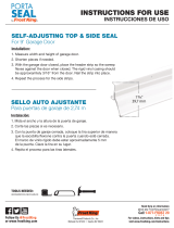
INSTALLATION STEP 5
Hangthe Opener
Threerepresentative installations are shown. Yours maybe
different. Hanging brackets should be angled (Figure 1) to provide
rigid support. On finished ceilings (Figures 2 and 3), attach a
sturdy metalbracket to structural supports before installing the
opener.This bracket and fastening hardwareare not provided.
1. Measurethe distancefrom eachside of the motor unit to the
structural support.
2. Cut both piecesof the hanging bracket to requiredlengths.
3. Drill 3/16" pilot holes in the structural supports.
4. Attach one end of eachbracketto a support with
5/16"-9xl-5/8" lag screws.
5. Fastenthe opener to the hanging brackets with
5/16"-18x7/8" hex bolts, lock washers and nuts.
6. Checkto makesure the rail is centered over the door (or in
line with the header bracketif the bracket is not centeredabove
the door).
7. Removethe 2x4. Operatethe door manually. If the door hits the
rail, raisethe header bracket.
NOTE:DONOTconnectpower to openerat this time.
HARDWARESHOWNACTUALSIZE
Lag Screw 5/16"-9xl-5/8"
HexBolt
5/1B"-18x7/8" Nut 5/16"-18 LockWasher 5/1B"
To avoid possible SERIOUSINJURYfrom a falling garage door
opener,fasten it SECURELYto structural supports of the
garage.Concreteanchors MUST be usedif installing ANY
brackets into masonry.
FigureI
Supports
Measure ',
Distance
Bolt 5/16"-18x7/8"
Lock Washer 5/16"
Nut 5/16"-18
Lag Screw
5/16"-9xl -5/8"
Figure2
Hidden .. _ -
Support _---
(Not Provided) .... _1 _j_-
_ -- FINISHEDCEILING
Lag Screw
5/16"-9xl-5/8" - _--
(Not Provided)
Bolt 5/16"-18x7/8"
_ Lock Washer 5/16"
Nut 5/16"-18
Bolt 5/16"-18x7/8"
Lock Washer 5/16"
Nut 5/16"-18
Figure3
Lag Screw
5/16"-9xl -5/8"
Bolt 5/16"-18x7/8"
Lock Washer 5/16"
Nut 5/16"-18
(Not Provided)
Bolt 5/16"-18x7/8"
Lock Washer 5/16"
Nut 5/16"-18
16

INSTALLATION STEP 6
Install theDoorControl
Locate the door control within sight of door, at a minimum height
of 5feet (1.5 m) where smallchildren cannot reach,away from
moving parts of door and door hardware. If installing into drywall,
drill 5/32" holes andusethe anchors provided. Forpre-wired
installations (as in new home construction), it may be mounted to
a single gang box (Figure1).
1. Strip 7/16" (11 mm) of insulation from one end of bell wire and
connect to the two screwterminals on the back of the door
control by color: white wire to 2 and white/red wire to the 1
(Figure 2).
2. Removecover by gently prying at slot in top of the cover with a
small flat head screwdriver (Figure3). Fastenwith 6ABxl"
self-tapping screws(drywall installation) or 6-32x1" machine
screws (into gang box) as follows:
• Install bottom screw, allowing 1/8" (3 mm) to protrude above
wall surface.
• Position the bottom of the door control on the screw head
and slide down to secure. Adjust screwfor snugfit.
• Drill and install top screw with care to avoid cracking plastic
housing. Do not overtighten.
• Insert top tabs and snap on cover.
3. (For standard installation only)Run bell wire up wall and
across ceiling to motor unit. Use insulated staplesto secure
wire inseveral places. Donot piercewire with a staple, creating
a short or open circuit.
4. Strip 7/16" (11 mm) of insulation from end of bell wire. Connect
bell wire to the quick-connect terminals as follows: white to
white and white/red to red (Figure4).
5. Positionthe antennawire as shown.
6. Usetacks or staplesto permanently attachentrapment warning
label to wall nearthe door control, and manual release/safety
reversetest labelin a prominent location on inside of garage
door.
NOTE:DONOTconnectpower and operate openerat this time.
Thetrolley will travel to the furl open position but will not return
to the closeposition until thesensor beamis connectedand
properly aligned.
Figure4
Door Control
Connections
To releaseor insert wire, pushin tab
with screwdriver tip
Strip wire 7/16" (11 ram)
(7/16"(11 mnU)
Red WhiteGrey
Smart Control Panel_'
/
o
To prevent possible SERIOUSINJURYor DEATHfrom
electrocution:
• DisconnectALL electric and batterypower BEFORE
performing ANY serviceor maintenance.
• ConnectONLYto 24 VOLTlow voltage wires.
To prevent possible SERIOUSINJURYor DEATHfrom a
closing garagedoor:
• Installthe door control within sight of garagedoor, out of
reachof children at a minimum height of 5 feet (1.5 m), and
away from ALL moving parts of door.
• NEVERpermit children to operateor play with door control
push buttons or remotecontrols.
• Activate door ONLYwhen it can be seenclearly, is properly
adjusted, andthere are no obstructions to door travel.
• ALWAYSkeepgarage door in sight until completely closed.
NEVERpermit anyoneto cross path of closing garagedoor.
HARDWARESHOWNACTUALSIZE
'''>
(std installation)
(Gang boxinstallation)
Insulated Staples
(Not shown)
Drywall Anchors
Figure1
PRE-WIREDINSTALLATION
Figure2
__i Top
Mounting
Bell ( + -- + I) Hole
W_ _,.,...__ __j:lk_ "_Terminal
screws
_--i--J __-lu-F-_---h_ Bottom
_ Pl Mounting
(BACKVIEW) Hole
Figure3
To Replace,
Insert Top
Push Bar Cover

INSTALLATION STEP 7
Install theBattery
1. Make sure motor unit is unplugged.
2. Usinga Phillips headscrewdriver, removethe batterycover on
the motor unit.
3. Partiallyinsert battery into motor unit with terminals facing out.
4. Connectthe red (+) and black (-) wires from motor unit to
corresponding terminals on battery.
5. Verify the batterywires are seated in the channel.
6. Replacebattery cover.
ALWAYSwear protective gloves and eyeprotection when
changing the battery or working around the battery
compartment.
INSTALLATION STEP 8
Install theLights
1. Pressthe releasetabs on both sides of lens. Gentlyrotate lens
back and downward until the lens hinge is in the fully open
position. Donot removethe lens.
2. Install upto a 100 watt maximum light bulb in eachsocket.
Light bulb size should be A19, standard neck only. Thelights
will turn ONand remainlit for approximately 4-1/2 minutes
when power is connected.Thenthe lights will turn OFF.
3. Reversethe procedureto close the lens.
4. UseA19,standard neck garagedoor opener bulbs for
replacement.
NOTE:Useonly standardlight bulbs. Theuseof short neck or
speciafity light bulbs may overheatthe endpanelor light socket.
To prevent possible OVERHEATINGof the endpanelor light
socket:
• DONOTuseshort neck or specialty light bulbs.
• DONOTuse halogen bulbs. UseONLYincandescent.
To prevent damageto the opener:
• DONOTuse bulbs larger than 100W.
• ONLYuseA19 sizebulbs.
ReleaseTab
100 Watt (Max)_
Standard Light Bulb f_,...____ _
/
/
/
100 Watt,
Standard Light Bulb
Lens
Hinge
18

INSTALLATION STEP 9
Attachthe EmergencyReleaseRopeandHandle
1. Insert one end of the emergencyreleaserope through the
handle.Make sure that "NOTICE"is right side up. Tie a knot at
least 1 inch (2.5 cm) from the end of the emergency release
rope.
2. Insert the other end of the emergency releaserope through the
hole in the trolley releasearm. Mount the emergencyrelease
within reach,but at least 6 feet (1.83 m) abovethe floor,
avoiding contact with vehiclesto preventaccidental releaseand
securewith a knot.
NOTE:If it is necessaryto cut the emergencyreleaserope, seal
the cut end with a match or lighter to prevent unraveling. Ensure
the emergencyreleaserope and handleare abovethe top of aft
vehiclesto avoid entanglement.
To prevent possible SERIOUSINJURYor DEATHfrom a falling
garagedoor:
• If possible, useemergency releasehandleto disengage
trolley ONLYwhen garagedoor is CLOSED.Weak or broken
springs or unbalanceddoor could result in an open door
falling rapidly and/or unexpectedly.
• NEVERuseemergency releasehandle unless garagedoorway
is clear of personsand obstructions.
• NEVERusehandle to pull door open or closed. If rope knot
becomes untied, you could fall.
Trolley
• !
_ _ Overhand
Emergency
_ Knot
ReleaseHandle
INSTALLATION STEP 10
Electrical Requirements
To avoidinstallationdifficulties,do notrunthe openerat this
time.
To reducethe risk of electric shock, your garagedoor openerhas
a grounding type plug with a third grounding pin. This plug will
only fit into agrounding type outlet. If the plug doesn't fit into the
outlet you have,contact a qualified electricianto install the proper
outlet.
To prevent possible SERIOUSINJURYor DEATHfrom
electrocution or fire:
• DisconnectALL electric and battery power BEFORE
performing ANY serviceor maintenance.
• Garagedoor installation and wiring MUSTbe in compliance
with ALL local electrical and building codes.
• NEVERusean extension cord, 2-wire adapter,or change
plug in ANYway to makeit fit outlet. Besure the opener is
grounded.
PERMANENTWIRING
CONNECTION
If permanent wiring isrequired byyourlocal code,refer to the
followingprocedure.
To makea permanent connection through the 7/8" hole in the top
of the motor unit:
1. Removethe motor unit cover screws and set the cover aside.
2. Removethe attached3-prong cord.
3. Connectthe black (line) wire to the screw on the brass terminal;
the white (neutral) wire to the screw on the silver terminal;
and the ground wire to the green ground screw.
The openermustbe grounded.
4. Reinstallthe cover.
To avoidinstallationdifficulties,do notrunthe openerat this
time.
19
Ground Tab
Green
Ground Screw
Ground Wire . Wire
White Wire BlackWire

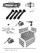
INSTALLATION STEP 1 1
Install TheProtectorSystem®
The safetyreversingsensormustbeconnectedandaligned
correctlybeforethe garagedooropenerwill movein the down
direction.
IMPORTANTINFORMATIONABOUTTHESAFETYREVERSING
SENSOR
When properly connectedand aligned, the sensor will detectan
obstacle in the pathof its electronic beam. Thesending eye
(with an amber indicator light) transmits aninvisible light beam
to the receivingeye(with a green indicator light). If an obstruction
breaks the light beamwhile the door is closing, the door will stop
and reverseto full open position, and the opener lights will flash
10 times.
The units must be installed inside the garageso that the sending
and receivingeyes face eachother across the door, no morethan
6" (15 cm) abovethefloor. Either can be installed on the left or
right of the door aslong as the sun never shines directly into the
receiving eyelens.
The mounting brackets are designedto clip onto the track of
sectional garagedoors without additional hardware.
Besure power is NOTconnectedto the garagedoor opener
BEFOREinstalling the safety reversing sensor.
To prevent SERIOUSINJURYor DEATHfrom a closing garage
door:
• Correctly connect and align the safety reversingsensor.
This required safety device MUSTNOTbe disabled.
• Install the safety reversing sensor so beamis NOHIGHER
than 6" (15cm) abovegaragefloor.
If it is necessaryto mount the units on the wall, the brackets must
be securely fastenedto a solid surface such as the wall framing.
Extensionbrackets (seeaccessories) are availableif needed.
If installing in masonry construction, add a pieceof wood at each
location to avoid drilling extra holesin masonry if repositioning
is necessary.
The invisible light beam path must be unobstructed. No part of the
garage door (or door tracks, springs, hinges, rollers or other
hardware) may interrupt the beamwhile the door is closing.
[ ! !oJ!Jl
_'af(_t5YcRm)max. I;v2_2_le_igAhr;aB_ _af(_t5YcRe_ermS2;? Sensor
above floor above floor
Facingthe doorfrom insidethe garage.
2O
/