Manual
EN
Handleiding
NL
Manuale
FR
Anleitung
DE
Manual
ES
Appendix
Phoenix Inverter Compact
12 | 1200 230V 24 | 1200 230V
12 | 1600 230V 24 | 1600 230V


Copyrights 2008 Victron Energy B.V.
All Rights Reserved
This publication or parts thereof may not be reproduced in any form, by any method, for any purpose.
For conditions of use and permission to use this manual for publication in other than the English
language, contact Victron Energy B.V.
VICTRON ENERGY B.V. MAKES NO WARRANTY, EITHER EXPRESSED OR IMPLIED, INCLUDING
BUT NOT LIMITED TO ANY IMPLIED WARRANTIES OF MERCHANTABILITY OR FITNESS FOR A
PARTICULAR PURPOSE, REGARDING THESE VICTRON ENERGY PRODUCTS AND MAKES
SUCH VICTRON ENERGY PRODUCTS AVAILABLE SOLELY ON AN “AS IS” BASIS.
IN NO EVENT SHALL VICTRON ENERGY B.V. BE LIABLE TO ANYONE FOR SPECIAL,
COLLATERAL, INCIDENTAL, OR CONSEQUENTIAL DAMAGES IN CONNECTION WITH OR
ARISING OUT OF PURCHASE OR USE OF THESE VICTRON ENERGY PRODUCTS. THE SOLE
AND EXCLUSIVE LIABILITY TO VICTRON ENERGY B.V., REGARDLESS OF THE FORM OF
ACTION, SHALL NOT EXCEED THE PURCHASE PRICE OF THE VICTRON ENERGY PRODUCTS
DESCRIBED HERE IN.
Victron Energy B.V. reserves the right to revise and improve its products as it sees fit. This publication
describes the state of this product at the time of its publication and may not reflect the product at all
times in the future


1
EN NL FR DE ES Appendix
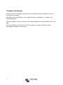
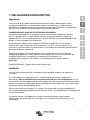
1. SAFETY INSTRUCTIONS
General
Please familiarize yourself with the safety features and instructions by first reading the
documentation supplied with this product before using the equipment. This product has
been designed and tested in accordance with international standards. The equipment
must be used exclusively for the purpose for which it was designed.
WARNING: ELECTRIC SHOCK HAZARD.
The product is used in conjunction with a permanent energy source (battery). Input and/or
output terminals may still be dangerously energized, even when the equipment is
switched off. Always switch off the AC supply and the battery before carrying out
maintenance or servicing the product.
The product has no internal user-serviceable components. Do not remove the front plate
or operate the product if any panels have been removed. All servicing must be
undertaken by qualified personnel.
Never use the product where there is a risk of gas or dust explosions. Consult the battery
manufacturer's information to ascertain that the product is intended for use in conjunction
with the battery. Always comply with the battery manufacturer's safety instructions.
WARNING: Do not lift heavy loads without assistance.
Installation
Read the installation instructions in the installation manual before installing the equipment.
This is a Safety Class I product (supplied with a protective grounding terminal). The chassis
must be grounded. A grounding point is located on the outside of the product. Whenever it is
likely that the grounding protection has been damaged, the product must be turned off and
secured against unintended operation; please contact qualified service staff.
Ensure that the DC and AC input cables are fused and fitted with circuit breakers. Never
replace a safety component with a different type. Consult the manual to determine the correct
component.
Before applying power, ensure that the available power source matches the configuration
settings of the product as described in the manual.
Ensure that the equipment is used under the correct ambient conditions. Never operate the
product in a wet or dusty environment. Ensure there is adequate free space for ventilation
around the product and check that the ventilation vents are not blocked.
Ensure that the required system voltage does not exceed the product's capacity.

2
Transport and Storage
Ensure that the mains power and battery leads have been disconnected before storing or
transporting the product.
No liability can be accepted for any transport damage if the equipment is shipped in non-
original packaging.
Store the product in a dry environment; the storage temperature must be between -20°C and
60°C.
Consult the battery manufacturer's manual in respect of transport, storage, charging,
recharging and disposal of the battery.

3
EN NL FR DE ES Appendix
2. DESCRIPTION
2.1 General
SinusMax - Superior engineering
Developed for professional duty, the Phoenix range of inverters is suitable for the widest
range of applications. The design criteria have been to produce a true sine wave inverter
with optimised efficiency but without compromise in performance. Employing hybrid HF
technology, the result is a top quality product with compact dimensions, light in weight
and capable of supplying power, problem-free, to any load.
Extra start-up power
A unique feature of the SinusMax technology is very high start-up power. Conventional
high frequency technology does not offer such extreme performance. Phoenix inverters,
however, are well suited to power up difficult loads such as compressors, electric motors
and similar appliances.
Parallel and 3-phase operation capability
Up to 6 inverters can operate in parallel to achieve higher power output.
Operation in 3-phase configuration is also possible.
To transfer the load to another AC source: the automatic transfer switch
If an automatic transfer switch is required, we recommend to using the MultiPlus or
Quattro instead. The switch is included in these products and the charger function of the
MultiPlus/Quattro can be disabled. Computers and other electronic equipment will continue to
operate without disruption because the MultiPlus/Quattro features a very short switchover
time (less than 20 milliseconds).
Programmable relay
The Phoenix Inverter is equipped with a programmable relay, which by default is set as an
alarm relay. The relay can be programmed for all kinds of other applications however, for
example as a starter relay for a generating set.
Programmable with DIP switches, VE.Net panel or personal computer
The Phoenix Inverter is supplied ready for use. Three features are available for changing
certain settings if desired:
- The most important settings can be changed in a very simple manner, using DIP switches.
- All settings, with exception of the programmable relay, can be changed with a VE.Net panel.
- All settings can be changed with a PC and free of charge software, downloadable from our
website www.victronenergy.com.

4
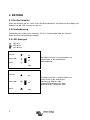
3. OPERATION
3.1 On/Off Switch
When switched to "on", the product is fully functional. The inverter will come into operation
and the LED "inverter on" will light up.
3.2 Remote control
Remote control is possible with a simple on/off switch or with a Phoenix Inverter Control
panel.
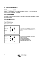
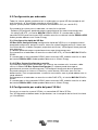
3.3 LED Indications
LED off
LED flashes
LED illuminated
The inverter is switched on and supplies
power to the load. Battery operation.
inverter
on
eco mode
off
alarm
eco
The inverter is switched on and supplies
power to the load.
Pre alarm: overload, or
battery voltage low, or
inverter temperature high
inverter
on
eco mode
off
alarm
eco
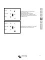
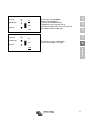
The inverter is switched off.
Alarm: overload, or
battery voltage low, or
inverter temperature hig, or
DC ripple voltage on battery
terminal was too high.
inverter
on
eco
mode
off
alarm
eco
The inverter is switched on ”eco mode”
and supplies power to the load.
inverter
on
eco mode
off
alarm
eco

5
EN NL FR DE ES Appendix
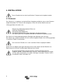
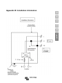
4. INSTALLATION
4.1 Location
The product must be installed in a dry and well-ventilated area, as close as possible to
the batteries. There should be a clear space of at least 10cm around the appliance for
cooling.
Excessively high ambient temperature will result in the following:
Reduced service life.
Reduced charging current.
Reduced peak capacity, or shutdown of the inverter.
Never mount the appliance directly above the batteries.
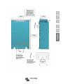
The product is suitable for wall mounting. For mounting see appendix A.
The appliance can be mounted horizontally as well as vertically; vertical mounting is
preferable. The vertical position offers optimum cooling.
Try and keep the distance between the product and the battery to a minimum in order to
minimize cable voltage losses.
For safety purposes, this product should be installed in a heat-resistant
environment if it is used with equipment where a substantial amount of power is
to be converted. You should prevent the presence of e.g. chemicals, synthetic
components, curtains or other textiles, etc., in the immediate vicinity.
This product should be installed by a qualified electrician.
The interior of the product must remain accessible after installation.

6
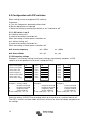
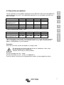
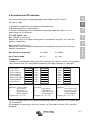
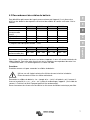
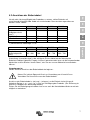
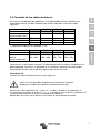
4.2 Connection of Battery cables
In order to fully utilize the full capacity of the product, batteries with sufficient capacity and
battery cables with sufficient cross section should be used. See table.
24/1200 24/1600 12/1200 12/1600
Recommended
cross section (mm
2
)
1,5
1
5 m 25 35 50 70
5 10 m 50 70 100 140
1) preassembled cable length: 1.5 m
24/1200 24/1600 12/1200 12/1600
Recommended
battery capacity (Ah)
40 – 400 100 – 400 150 – 700 200 – 700
Remark: Internal resistance is the important factor when working with low capacity batteries.
Please consult your supplier or the relevant sections of our book “electricity on board”,
downloadable from our website.
Procedure
Proceed as follows to connect the battery cables:
Use an insulated box spanner in order to avoid shorting the battery.
Avoid shorting the battery cables.
Connect the battery cables: the + (red) and the - (black), to the battery see appendix A.
Reverse polarity connection (+ to – and – to +) will cause damage to the product. (Safety fuse
inside the MultiPlus Compact can be damaged)
Secure the nuts tightly in order to reduce the contact resistance as much as possible.

7
EN NL FR DE ES Appendix
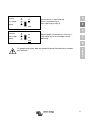
4.3 Connection of the AC cabling
This is a Safety Class I product (supplied with a protective grounding
terminal).
The neutral wire of the AC output of this inverter is connected to the
chassis.
This is to ensure proper functioning of a GFCI (or RCCB) to be installed in the
AC output of the Inverter.
The chassis of the product must be connected toground, to the frame (of a
vehicle) or the ground plate or hull (of a boat).
Procedure
The AC output cable can be connected directly to the male-connector at the bottom of the
enclosure. (the connector pulls out!)
The terminal points are indicated clearly. From left to right: “N” (neutral), earth, and “L1”
(phase).
Use a three-wire cable with a flexible core and a cross section of 1.5 or 2.5 mm².
4.4 Optional Connections
A number of optional connections are possible:
4.4.1 Remote on/off switch & remote Control panel
The product can be remotely controlled in two ways.
- With an external switch (connection terminal H, see appendix A). Operates only if the switch
on the Inverter is set to “on”.
- With a Phoenix Inverter Control panel (connected to one of the two RJ48 sockets C, see
appendix A). Operates only if the switch on the inverter is set to “on”.
Only one remote control can be connected, i.e. either a switch or a remote control
panel.
4.4.2. Programmable relay
The inverters are equipped with a multi-functional relay that by default is programmed as an
alarm relay. (VEConfigure software needed to change relay functionality).

8
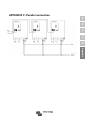
4.4.3 Parallel Connection
The inverters can be connected in parallel with several identical devices. To this end, a
connection is established between the devices by means of standard RJ45 UTP cables. The
system (one or more inverters plus optional control panel) will require subsequent
configuration (see Section 5).
In the event of connecting inverters in parallel, the following requirements must be met:
- A maximum of six units connected in parallel.
- Only identical devices may be connected in parallel.
- The DC connection cables to the devices must be of equal length and cross-section.
- If a positive and a negative DC distribution point is used, the cross-section of the connection between the
batteries and the DC distribution point must at least equal the sum of the required cross-sections of the
connections between the distribution point and the inverters.
- Place the inverters close to each other, but allow at least 10 cm for ventilation purposes under, above and
beside the units.
- UTP cables must be connected directly from one unit to the other (and to the remote panel).
Connection/splitter boxes are not permitted.
- Only one remote control means (panel or switch) can be connected to the system.
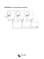
4.4.4 Three-phase operation
The Phoenix Inverter can also be used in 3-phase configuration. To this end, a connection
between the devices is made by means of standard RJ45 UTP cables (the same as for
parallel operation). The system (Inverters plus an optional control panel) will require
subsequently configuration (see Section 5).
Pre-requisites: see Section 4.4.3.

9
EN NL FR DE ES Appendix
5. CONFIGURATION
5.1 Standard settings: ready for use
On delivery, the Phoenix inverter is set to standard factory values. In general, these
settings are suitable for stand-alone operation.
Standard factory settings
Inverter frequency 50 Hz
Inverter voltage 230 VAC
Stand-alone / parallel / 3-phase stand-alone
Search mode off
Programmable relay alarm function
5.2 Explanation of settings
Inverter frequency
Output frequency
Adjustability: 50Hz; 60Hz
Inverter voltage
Adjustability: 210 – 245V
Stand-alone / parallel operation / 2-3 phase setting
Using several devices, it is possible to:
- Increase total inverter power (several devices in parallel).
- Create a split-phase system.
- Create a 3-phase system.
The standard product settings are for standalone operation. For parallel, three phase or split
phase operation see section 4.4.3 and 4.4.4.
Settings may only be changed by a qualified engineer.
Carefully read the instructions before changes are made.
Batteries should be placed in a dry and well-ventilated area during charging.

10
Search Mode (Applicable in stand-alone configuration only)
If search mode is ‘on’, the power consumption in no-load operation is decreased by approx.
70%. In this mode the Compact, when operating in inverter mode, is switched off in case of no
load or very low load, and switches on every two seconds for a short period. If the output
current exceeds a set level, the inverter will continue to operate. If not, the inverter will shut
down again.
The Search Mode can be set with a DIP switch.
The Search Mode “shut down” and “remain on” load levels can be set with VEConfigure.
The standard settings are:
Shut down: 40 Watt (linear load).
Turn on: 100 Watt (linear load).
AES (Automatic Economy Switch)
Instead of the search mode, the AES mode can also be chosen (with help of VEConfigure
only).
If this setting is turned ‘on’, the power consumption in no-load operation and with low loads is
decreased by approx. 20%, by slightly 'narrowing' the sinusoidal voltage.
Not adjustable with DIP switches.
Applicable in stand-alone configuration only.
Programmable relay
By default, the programmable relay is set as an alarm relay, i.e. the relay will de-energise in
the event of an alarm or a pre-alarm (inverter almost too hot, ripple on the input almost too
high, battery voltage almost too low).
Not adjustable with DIP switches.

11
EN NL FR DE ES Appendix
5.3 Configuration by computer
All settings can be changed by means of a computer or with a VE.Net panel (except for
the multi-functional relay and the VirtualSwitch when using VE.Net).
Some settings can be changed with DIP switches (see Section 5.2).
For changing settings with the computer, the following is required:
- VEConfigureII software: can be downloaded free of charge at www.victronenergy.com.
- A RJ45 UTP cable and the MK2.2b RS485-to-RS232 interface. If the computer has no
RS232 connection, but does have USB, a RS232-to-USB interface cable is needed.
Both are available from Victron Energy.
5.3.1 VE.Bus Quick Configure Setup
VE.Bus Quick Configure Setup is a software program with which one Compact unit or
systems with a maximum of three Compact units (parallel or three phase operation) can
be configured in a simple manner. VEConfigureII forms part of this program.
The software free can be downloaded free of charge at www.victronenergy.com.
For connection to the computer, a RJ45 UTP cable and the MK2.2b RS485-to-RS232
interface is required.
If the computer has no RS232 connection, but does have USB, a RS232-to-USB
interface cable is needed. Both are available from Victron Energy.
5.3.2 VE.Bus System Configurator and dongle
For configuring advanced applications and/or systems with four or more inverters,
VE.Bus System Configurator software must be used. The software can be downloaded
free of charge at www.victronenergy.com. VEConfigureII forms part of this program.
The system can be configured without a dongle, and will be fully functional during 15 minutes
(as a demonstration facility). For permanent use, a dongle – available at additional charge – is
required.
For connection to the computer, a RJ45 UTP cable and the MK2.2b RS485-to-RS232
interface is required.
If the computer has no RS232 connection, but does have USB, a RS232-to-USB interface
cable is needed. Both are available from Victron Energy.
5.4 Configuration with a VE.Net panel
To this end, a VE.Net panel and the VE.Net to VE.Bus converter are required.
With VE.Net you can set all parameters, with the exception of the multi-functional relay and
the VirtualSwitch.

12
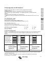
5.5 Configuration with DIP switches
Some settings can be changed with DIP switches
Procedure:
a) Turn the Compact on, preferably without load.
b) Set the dipswitches as required.
c) Store the settings by moving Dip switch 8 to “on” and back to “off”.
5.5.1. DIP switch 1 and 2
ds1 (default setting “off”).
If no panel connected: should be “off”.
When connecting a Control panel: should be “on”.
ds2: (default setting “on”).
If no panel connected: should be “on”.
When connecting a Control panel: should be “off”.
ds5: Inverter frequency off = 50Hz on = 60Hz
ds6: Search Mode off = off on = on
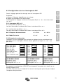
5.5.2 Exemplary settings
Example 1 is the factory setting (since factory settings are entered by computer, all DIP
switches of a new product are set to ‘off’, except for DS-2).
DS-1 Panel option off
DS-2 Panel option on
DS-3 Not used
DS-4 Not used
DS-5 Frequency
DS-6 Search mode off
DS-7 Not used
DS-8 Store setting
→
←
DS-1 off
DS-2 on
DS-3
DS-4
DS-5 off
DS-6 off
DS-7
DS-8
→
←
DS-1 on
DS-2 off
DS-3
DS-4
DS-5 on
DS-6 on
DS-7
DS-8
→
←
Example 1: (factory setting)
1 No panel connected
2 No panel connected
5 Frequency: 50Hz
6 Search mode off
8 store setting: off→ on→ off
Example 2
1 No panel connected
2 No panel connected
5 Frequency: 50Hz
6 Search mode off
8 store setting: off→ on→ off
Example 3
1 Panel connected
2 Panel connected
5 Frequency: 60Hz
6 Search mode on
8 store setting: off→ on→ off
Store the settings (DS3-DS7) by changing switch ds-8 from off to on, and then back to off.
The LED’s ‘Inverter’ and ‘eco mode’ and ‘alarm’ will flash four times to indicate acceptance of
the settings.

13
EN NL FR DE ES Appendix
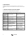
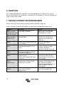
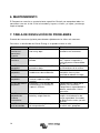
6. MAINTENANCE
The Compact does not require specific maintenance. It will suffice to check all
connections once a year. Avoid moisture and oil/soot/vapours, and keep the device clean.
7. TROUBLE SHOOTING TABLE
Proceed as follows for quick detection of common faults.
Consult your Victron Energy dealer if the fault cannot be resolved.
Problem Cause Solution
The inverter fails
to operate when
switched on.
The battery voltage is too high
or too low.
Ensure that the battery voltage
is within the correct value.
The inverter fails
to operate
Processor in no function-mode. Switch Front switch off, wait 4
seconds
Switch front switch on.
The alarm LED
flashes.
Pre-alarm alt. 1. The DC input
voltage is low.
Charge the battery or check the
battery connections.
The alarm LED
flashes
Pre-alarm alt. 2. The ambient
temperature is too high.
Place the inverter in a cool and
well-ventilated room, or reduce
the load.
The alarm LED
flashes.
Pre-alarm alt. 3. The load on the
inverter is higher than the
nominal load.
Reduce the load.
The alarm LED
flashes.
Pre-alarm alt. 4. Voltage ripple
on the DC input exceeds
1.25Vrms.
Check the battery cables and
terminals.
Check the battery capacity;
increase if necessary.
The alarm LED
flashes
intermittantly.
Pre-alarm alt. 5. Low battery
voltage and excessive load.
Charge the batteries, reduce
the load or install batteries with
a higher capacity. Use shorter
and/or thicker battery cables.
The alarm LED is
on
The inverter did cut out following
a pre-alarm.
Check the table for the
appropriate course of action.

14
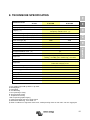
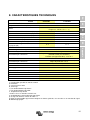
8. TECHNICAL DATA
1) Can be adjusted to 60Hz and to 240V
2) Protection
a. Output short circuit
b. Overload
c. Battery voltage too high
d. Battery voltage too low
e. Temperature too high
f. 230VAC on inverter output
g. Input voltage ripple too high
3) Non linear load, crest factor 3:1
4) Programmable relay which can be set for general alarm, DC undervoltage or genset start signal function
Phoenix Inverter
12 Volt
24 Volt
C 12/1200
C 24/1200
C 12/1600
C 24/1600
INVERTER
Input voltage range (V DC) 9,5 – 17 V 19 – 33 V
Output
Output voltage: 230 VAC ± 2%
Frequency: 50 Hz ± 0,1% (1)
Cont. output power at 25 °C (VA) (3) 1200 1600
Cont. output power at 25 °C (W) 1000 1300
Cont. output power at 40 °C (W) 900 1200
Peak power (W) 2400 3000
Maximum efficiency (%) 92 / 94 92 / 94
Zero-load power (W) 8 / 10 8 / 10
Zero load power in search mode (W) 2 / 3 2 / 3
GENERAL
Programmable relay (4) yes
Protection (2) a - g
Common Characteristics
Operating temp. range: -20 to +50°C (fan assisted
cooling) Humidity (non condensing) : max 95%
ENCLOSURE
Common Characteristics
Material & Colour: aluminium (blue RAL 5012)
Protection category: IP 21
Battery-connection Battery cables of 1.5 meter
230 V AC-connection G-ST18i connector
Weight (kg) 10
Dimensions (hxwxd in mm) 375x214x110
STANDARDS
Safety EN 60335-1, EN 60335-2-29
Emission / Immunity EN55014-1, EN 55014-2, EN 61000-3-3
Page is loading ...
Page is loading ...
Page is loading ...

4
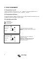
3. BEDIENING
3.1 On/Off schakelaar
Wanneer de schakelaar op “on” wordt geschakeld werkt het apparaat volledig.
De omvormer zal inschakelen en de LED “inverter on” zal gaan branden.
3.2 Afstandsbediening
Afstandsbediening is mogelijk met een simpele aan/uit schakelaar of met een Phoenix
Inverter Control paneel.
3.3 LED Indicaties
LED uit
LED knippert
LED brandt
Batterij bedrijf. De omvormer staat aan en
levert vermogen aan de belasting.
inverter
on
eco mode
off
alarm
eco
De omvormer is ingeschakeld en levert
vermogen aan de belasting.
Voor-alarm: overbelasting, of
accu spanning te laag, of
omvormer temperatuur hoog
inverter
on
eco mode
off
alarm
eco

5
EN NL FR DE ES Appendix
De omvormer is uitgeschakeld.
Alarm: overbelasting, of
accu spanning te laag, of
inverter
on
eco
mode
off
alarm
eco
Batterij bedrijf. De omvormer staat aan in
“eco mode” en levert vermogen aan de
belasting.
inverter
on
eco mode
off
alarm
eco
Dit product mag alleen door een gekwalificeerde elektrotechnicus worden
geïnstalleerd.
Page is loading ...
Page is loading ...
Page is loading ...
Page is loading ...
Page is loading ...
Page is loading ...
Page is loading ...
Page is loading ...
Page is loading ...
Page is loading ...
Page is loading ...
Page is loading ...
Page is loading ...
Page is loading ...
Page is loading ...
Page is loading ...
Page is loading ...
Page is loading ...
Page is loading ...
Page is loading ...
Page is loading ...
Page is loading ...
Page is loading ...
Page is loading ...
Page is loading ...
Page is loading ...
Page is loading ...
Page is loading ...
Page is loading ...
Page is loading ...
Page is loading ...
Page is loading ...
Page is loading ...
Page is loading ...
Page is loading ...
Page is loading ...
Page is loading ...
Page is loading ...
Page is loading ...
Page is loading ...
Page is loading ...
Page is loading ...
Page is loading ...
Page is loading ...
Page is loading ...
Page is loading ...
Page is loading ...
Page is loading ...
Page is loading ...
Page is loading ...
Page is loading ...
Page is loading ...
Page is loading ...
Page is loading ...
Page is loading ...
Page is loading ...
Page is loading ...
Page is loading ...
Page is loading ...
Page is loading ...
Page is loading ...
Page is loading ...
Page is loading ...
Page is loading ...
Page is loading ...
Page is loading ...
Page is loading ...
Page is loading ...
Page is loading ...
-
 1
1
-
 2
2
-
 3
3
-
 4
4
-
 5
5
-
 6
6
-
 7
7
-
 8
8
-
 9
9
-
 10
10
-
 11
11
-
 12
12
-
 13
13
-
 14
14
-
 15
15
-
 16
16
-
 17
17
-
 18
18
-
 19
19
-
 20
20
-
 21
21
-
 22
22
-
 23
23
-
 24
24
-
 25
25
-
 26
26
-
 27
27
-
 28
28
-
 29
29
-
 30
30
-
 31
31
-
 32
32
-
 33
33
-
 34
34
-
 35
35
-
 36
36
-
 37
37
-
 38
38
-
 39
39
-
 40
40
-
 41
41
-
 42
42
-
 43
43
-
 44
44
-
 45
45
-
 46
46
-
 47
47
-
 48
48
-
 49
49
-
 50
50
-
 51
51
-
 52
52
-
 53
53
-
 54
54
-
 55
55
-
 56
56
-
 57
57
-
 58
58
-
 59
59
-
 60
60
-
 61
61
-
 62
62
-
 63
63
-
 64
64
-
 65
65
-
 66
66
-
 67
67
-
 68
68
-
 69
69
-
 70
70
-
 71
71
-
 72
72
-
 73
73
-
 74
74
-
 75
75
-
 76
76
-
 77
77
-
 78
78
-
 79
79
-
 80
80
-
 81
81
-
 82
82
-
 83
83
-
 84
84
-
 85
85
-
 86
86
-
 87
87
-
 88
88
-
 89
89
-
 90
90
-
 91
91
-
 92
92


Victron energy 12-1600 230V Owner's manual
- Type
- Owner's manual
- This manual is also suitable for
Ask a question and I''ll find the answer in the document
Finding information in a document is now easier with AI
in other languages
Related papers
-
Victron energy Inverter Compact 1200 1600 Owner's manual
-
-
Victron energy 12-2000 230V User manual
-
-
-
-
-
-
-