Page is loading ...

2
2
1
LH
7
)[
7
8
8NBY
"
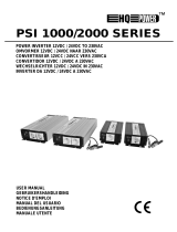
AC power
socket
12 V DC
power socket
USB power
socket
64#PVU
N"

5
GB
Power Inverter
SAFETY INSTRUCTIONS
To ensure reliable service your power inverter must be
installed and used properly.
Read and understand the installation and operating
thoroughly prior to installation and use. Pay particular
attention to the WARNING and CAUTION statements
in this manual.
CAUTION statements advise against certain condi-
tions and practices that may result in damage to your
inverter.
WARNING statements identify the conditions or prac-
tices that may result in injury or death.
PLEASE READ ALL THE INSTRUCTIONS BEFORE
USING THIS POWER INVERTER.
WARNING:
To reduce this risk of fi re, electric shock, explosion or
injury:
● Do not connect to AC distribution wiring.
● Always disconnect appliances from the inverter and
turn the inverter off before working the appliance.
Multiple outlet power strips with switches and power
switches and circuit breakers only interrupt power
to the “live” socket terminals. The neutral terminals
remain powered with respect to the earth terminals.
● Do not make any electrical connections or discon-
nections in areas designated as IGNITION PRO-
TECTED including DC cigarette lighter type plug
connections and ring terminal connections. Always
disconnect appliance from the inverter before re-
moving the inverter power source.
● Do not obstruct or block the air vents on the invert-
er.
● The inverter is not a toy, keeps away from children.
CAUTION:
● Do not use with positive earth electrical systems (the
majority of modern vehicles are negative earth). A
reverse polarity connection will result in a blown fuse
and may cause permanent damage to the inverter.
● The inverter will not operate high wattage applianc-
es or equipment that produces heat, such as dryers,
microwave ovens and toasters.
● Earthing the neutral will cause the inverter to shut
down.
● Do not operate the inverter if it is wet. Water and
electric do not mix.
● Do not install the inverter in the engine compart-
ment, the inverter must be used in a well ventilated
position.
● This inverter is not tested for use with medical equip-
ment.
IMPORTANT CABLE INFORMATION
Substantial power loss and reduced battery operating
time result from inverters installed with cables that are
not able to supply full power. Symptoms of low battery
power can result from cables that are either excessively
long or of an insuffi cient gauge. Marine installations are
subjected to vibration and stresses that exceed those
of other mobile installations, therefore the installer/op-
erator should be especially aware of the requirements
to maintain secure, tight water resistant electrical con-
nections and provide for strain relief for DC cables and
appliance wiring. Cable insulation must be the appro-
priate type for the environment.
INTRODUCTION
The inverter supplies continuous power in the form of
one household type socket. The inverter has enough
power to run almost any household or electronic appli-
ance. Safety features include automatic shut down and
a low battery alarm to prevent damage to your battery.
CONTROLS, INDICATORS AND CONNEC-
TORS
The front panel of the inverter provides two LED indica-
tors. The green LED indicator shows the unit is working
correctly when lit. The red LED indicator shows inverter
shut down from overload, over voltage or over temper-
ature. The inverter is fi tted with an on/off switch, the on/
off switch is also used to force reset the inverter circuits
in case of overload, over voltage or over temperature.
Power is supplied through the three pin AC plug and
DC input power is supplied via the rear panel.
HOW INVERTERS WORK
Principle of operation
The inverter converts low voltage DC (direct current)
from a battery or other power source to standard AC
(alternating current) household power. The inverter
converts power in two stages. The fi rst stage is a DC to
DC conversion process that raises low voltage DC from
the inverter input to high volt DC. The second stage is
the actual inverter stage that converts the high DC into
AC power.
The DC to DC converter stage uses modern high
frequency power conversion techniques that have re-
placed bulky transformers found in less technologically
advanced models. The inverter uses advanced MOS-
FET transistors in a full bridge confi guration, which
ensures excellent overload capabilities and allows the
inverter to operate reactive loads such as small induc-
tion motors.
The output waveform
The AC output waveform is known as a “modifi ed sine
wave”. It is a waveform that has characteristics similar
to the sine wave shape of standard household power.
This type of switching power is suitable for most AC
load, including linear and switching power supplies
used in electronic equipment, transformers and mo-
tors.

6
GB
• Connect the red cable to the post marked positive
(+) on the back panel of the inverter. Connect the
red battery clip to the positive (+) terminal of the bat-
tery.
• Check that all the connections between battery clips
and terminals are secure
CAUTION:
Loose connections may cause overheated wires and
melted insulation. Check to make sure you have not
reversed the polarity.
Connection to load
The inverter is equipped with a standard AC household
type socket. Plug the cord from the appliance you wish
to use into the socket. Make sure that the combined
load requirement of your equipment does not exceed
the rated watts.
The inverter is engineered to be connected directly
to standard electrical and electronic equipment in the
manner described above. Do not connect the power
inverter to household or recreational vehicle AC distri-
bution wiring .Do not connect the inverter to any AC
load circuit in which the neutral conductor is connected
to earth or the negative of the DC (battery) source.
WARNING:
Never connect to AC distribution wiring.
CAUTION: RECHARGEABLE APPLIANCES
Certain rechargeable devices are designed to be re-
charged by plugging them directly in to a household
socket. This type of device must never be used in the
inverter. The device will damage the inverter. Do not
use the inverter to recharge items that can be plugged
directly into a household socket. This problem does not
occur with the vast majority of battery-operated equip-
ment. Most of these devices use a separate charger
or transformer that is plugged into an AC household
socket. The inverter is easily capable of running most
chargers and transformers.
POSITIONING THE INVERTER
For best operating results, the inverter should be
placed on a fl at surface such as the ground, car fl oor
or seat, or another solid surface. The unit is equipped
with a 1 meter-power cord for easy positioning. The in-
verter should only be used in locations that meet the
following criteria.
• Dry : do not allow water or liquids to come into con-
tact with the inverter
• Cool: ambient air temperature should be between
-1 ºС non-condensing, and 40 ºС. Do not place the
inverter on or near a heating vent or any equipment,
which is generating heat above room temperature
keep the inverter out of direct sunlight.
Ventilated: keep the area surrounding the inverter clear
to ensure free air circulation around the unit. Do not
place items on or near the unit whilst it is operating. A
fan is helpful if the unit is operating at maximum power
outputs for extended periods of time. If the internal tem-
perature of the inverter exceeds 90 ºС the inverter will
shut down and restart when it has cooled.
The modifi ed sine wave produced by the inverter has
an RMS (root mean square) voltage, which is the same
as standard household power. Most AC voltmeters
(analog and digital) are sensitive to the average value
of the waveform rather than the RMS value. They are
calibrated for RMS voltage under the assumption that
waveform measured will be a pure sine wave. Voltme-
ters will not read the RMS voltage of a modifi ed sine
wave correctly. The reading will be around 20-30 volts
too low when measuring the inverters output.
INSTALLING THE INVERTER
Power source requirements
The power source for the inverter must provide be-
tween 11 and 15 volts DC and must be able to supply
the necessary current to operate the load. The power
source may be a battery or a well regulated DC power
supply. To obtain a rough estimate of the current in
Amps the power source must deliver simply divide the
power consumption of the load by 10.
Example: If a load is rated at 700 watts AC, the power
source must be able to deliver 700 by 10=70Amps.
CAUTION:
The inverter must be connected only to batteries with a
nominal output voltage of 12 volts. The inverter will not
work if connected to a 6 volts battery and will sustain
permanent damage if connected to a 24 volts battery.
Connecting to the power source
The inverter is equipped with a cigarette lighter plug
and battery clip cables (Inverter of 150 watts output
without battery clip cables) for connection directly to
the power source.
Using the fused cigarette lighter plug
The cigarette lighter plug is suitable for operating the
inverter at power outputs up to 150 watts. The tip of the
plug is positive and the side contact negative. Connect
the inverter to the power source by fi rmly inserting the
cigarette lighter plug into the cigarette lighter socket.
CAUTION:
Connect directly to battery or power source when
operating above 150watts.
NOTE:
Most vehicle cigarette lighter circuits use fuses rated at
15 to 20 amps or greater. To operate at full output use
the battery clip cable.
Connecting to a power source using provided ca-
bles
If the inverter is to be used for extended periods at
power levels above 150 watts, direct connection to the
power source is required. Use the leads provided to
connect directly to the 12-volt power source using the
following guidelines
• Check that the inverter is switched off and no fl am-
mable fumes are present
• Connect the black cable to the post marked nega-
tive (-) on the back panel of the inverter Connect the
black clip to the negative (-) terminal the battery

7
GB
• Overload protection: The inverter will automatically
shut down when the continuous power consumption
is over the rated Max power output.
• Overheating protection: When the temperature sen-
sor inside the inverter reaches 65 degrees C, the
unit will automatically shut down. In this instance,
allow at least 15 minutes before attempting to restart
the inverter and always disconnect appliances.
• Low battery alarm: The alarm will sound if the input
voltage drops below 10.5V,this is an indication that
the battery needs to be recharged. Users should dis-
continue operation of the appliance(s) at this point,
as the inverter will shut down shortly after the alarm
sounds. The vehicle engine should be started to re-
charge the battery. If the low battery alarm sounds
when the battery is fully charged follow the steps for
solving lack of output power in the troubleshooting
guide.
The alarm will sound if the inverter is overloaded, over-
heated or if there is an excessive voltage drop between
the battery and inverter.
NOTE:
It is normal for the alarm to sound while the unit is being
connected to, or disconnected from the power source,
this is not indicative of a problem.
TROUBLE SHOOTING
No AC output
• Inverter is too hot
• Disconnect load from inverter. Operate inverter with-
out load for a few minutes. Reconnect load.
Motorised power tool won’t start
• Excessive start up load
• If appliance does not start, then appliance is drawing
excessive wattage and will not work with inverter
Motorised power tool does not operate at correct
speed
• purely inductive load
• Make the load not purely inductive. Operate an in-
candescent lamp at same time as motor
Television/Radio interference
• Snow in picture, buzz in speaker
• Keep inverter and antenna distant from each other.
Use shielded antenna cable. Connect antenna to
amplifi er
• Safe: do not position the inverter near any fl amma-
ble material or in a position that may accumulate
fl ammable fumes or gases.
OPERATING TIPS
Rated versus actual current draw.
Most electrical equipment has labels that indicate the
power consumption in amps or watts. Ensure the power
consumption of the item you wish to operate is speci-
fi ed at the rated watts or less. The inverter has over-
load protection so it is safe to try and operate equip-
ment rated at the specifi ed watts or less. The inverter
will shut down if it is overloaded. The overload must be
removed before the inverter will restart; resistive loads
are the easiest for the inverter to run. However larger
resistive loads, such as, stoves and heaters usually
require more wattage than the inverter can deliver on
a continuous basis. Inductive loads such as, TV’s and
stereos require more current to operate than resistive
loads of the same wattage rating. Induction motors as
well as some televisions may require 2-6 times their
wattage rating to start up. The most demanding in this
category are those that start under load such as, com-
pressors and pumps. Testing is the only defi nitive way
of determining if a specifi c load can be started and how
long it will run. The inverter is fi tted with overload pro-
tection so will simply shut down if overloaded. To restart
the unit after overloading remove the overload and if
necessary turn the power switch off and then on.
Battery operating time.
With a typical vehicle battery, a minimum operating time
of 2 to 3 hours can be expected. In most instances, 5
to 10 hours of operating time is achievable however
it is recommended that the operator starts the vehicle
every 2 to 3 hours to recharge the battery system thus
guarding against unexpected equipment shut down
and ensuring that there is still suffi cient power to start
the engine. The inverter’s built in alarm will sound if
the DC voltage drops below 10.5V. The inverter can
be used whether or not the vehicles engine is running
however the inverter will not operate whilst the engine
is being turned over as battery voltage drops substan-
tially whilst the engine is being started. In most cases
the inverter can be left connected to the battery when
not in use as it draws very little current, however if the
vehicle is to remain unused for several days disconnect
the inverter from the battery.
In built protection.
Your inverter monitors the following potentially hazard-
ous conditions:
• Low battery voltage: This condition is not harmful to
the inverter but could damage the power source. An
audible signal will sound when input voltage drops
to 10,5 V. The inverter automatically shuts down
when input voltage drops to 10.0V. When the power
source input voltage is above 10.5V the inverter may
be restarted.
• Over voltage protection: The inverter will automati-
cally shut down when the input voltage exceeds
15.5V DC
• Short circuit protection: The inverter will shut down.
Remove the short circuit and the inverter will reset.

15
Мы с полной ответственностью заявляем, что настоя-
щее изделие соответствует следующим стандартам и
нормативным документам: EN 55022:2006+A1:2007;
EN 61000-3-2:2006+A2:2009; EN 61000-3-3:2008; EN
55024:1998+A2:2003 - согласно правилам: 2006/42/
EEC, 2006/95/EEC, 2004/108/EEC.
ЗАЯВЛЕНИЕ О СООТВЕТСТВИИRU
Product managament
V. Nosik
SBM group GmbH
Kurfürstendamm 21
10719 Berlin, Germany
Wir erklären in alleiniger Verantwortung, daß dieses
Produkt mit den folgenden Normen oder normativen
Dokumenten übereinstimmt: EN 55022:2006+A1:2007;
EN 61000-3-2:2006+A2:2009; EN 61000-3-3:2008; EN
55024:1998+A2:2003 gemäß den Bestimmungen der
Richtlinien 2006/42/ЕG, 2006/95/ЕG, 2004/108/ЕGС.
KONFORMITÄTSERKLÄRUNGDE
Vi erklærer under almindeligt ansvar, at dette produkt
er i overensstemmelse med følgende normer eller
normative dokumenter: EN 55022:2006+A1:2007; EN
61000-3-2:2006+A2:2009; EN 61000-3-3:2008; EN
55024:1998+A2:2003 i henhold til bestemmelserne i di-
rektiverne 2006/42/EØF, 2006/95/EØF, 2004/108/EØF.
KONFORMITETSERKLÆRINGDK
We declare under our sole responsibility that this prod-
uct is in conformity with the following standards or
standardized documents: EN 55022:2006+A1:2007;
EN 61000-3-2:2006+A2:2009; EN 61000-3-3:2008;
EN 55024:1998+A2:2003 in accordance with the regu-
lations 2006/42/ЕEС, 2006/95/ЕEС, 2004/108/ЕEС.
DECLARATION OF CONFORMITYGB
Nous déclarons sous notre propre responsabilité que
ce produit est en conformité avec les normes ou docu-
ments normalisés suivants: EN 55022:2006+A1:2007;
EN 61000-3-2:2006+A2:2009; EN 61000-3-3:2008; EN
55024:1998+A2:2003 conforme aux réglementations
2006/42/СEE, 2006/95/СEE, 2004/108/СEE.
DÉCLARATION DE CONFORMITÉFR
Wij verklaren, dat dit product voldoet aan de vol-
gende normen of normatieve documenten: EN
55022:2006+A1:2007; EN 61000-3-2:2006+A2:2009;
EN 61000-3-3:2008; EN 55024:1998+A2:2003
overeenkomstig de bepalingen van de richtlijnen
2006/42/ЕEG, 2006/95/ЕEG, 2004/108/ЕEG.
CONFORMITEITSVERKLARINGNL
HINWEISE ZUM UMWELTSCHUTZ
DE
Alt-Elektrogeräte sind Wertstoffe, sie gehören daher nicht in den
Hausmüll!
Wir möchten Sie daher bitten, uns mit Ihrem aktiven Beitrag bei
der Ressourcenschonung und beim Umweltschutz zu unterstüt-
zen und dieses Gerät bei den-falls vorhandeneingerichteten
Rücknahmestellen abzugeben.
ENVIRONMENTAL PROTECTION
GB
Discarded electric appliances are recyclable and should not be
discarded in the domestic waste! Please actively support us in
conserving resources and protecting the environment by
returning this appliance to the collection centres (if available).
INFORMATIONS SUR LA
PROTECTION DE L’ENVIRONNEMENT
FR
Tout appareil électrique usé est une matière recyclable et ne fait
pas pas partie des ordures ménagères! Nous vous demandons
de bien vouloir nous soutenir en contribuant activement au mé-
nagement des ressources et à la protection de l’environnement
en déposant cet appareil dans sites de collecte(si existants).
RICHTLIJNEN VOOR
MILIEUBESCHERMING
NL
Gebruikte elektronische apparaten horen niet thuis in het hui-
safval!
Wij vragen u daarom een bijdrage aan de bescherming van ons
milieu te leveren en dit apparaat op de voorziene verzamelpla-
atsen af te geven.
ANVISNINGER OM
MILJØBESKYTTELSE
DK
Kasserede elektriske apparater indeholder materiale, der kan
genbruges, og bør derfor aldrig smides væk som almindeligt af-
fald. Når dette apparat skal kasseres, vil vi derfor opfordre Dem
til at aflevere det på et egnet opsamlingssted, hvis et sådant fin-
des, og således være med til at bevare ressourcer og beskytte
miljøet.
УКАЗАНИЯ ПО ЗАЩИТЕ
ОКРУЖАЮЩЕЙ СРЕДЫ
RU
Старые электроприборы подлежат вторичной переработке и поэ-
тому не могут быть утилизированы с бытовыми отходами! Поэтому
мы хотели бы попросить Вас активно поддержать нас в деле эконо-
мии ресурсов и защиты окружающей среды и сдать этот прибор в
приемный пункт утилизации (если таковой имеется).

RU
Warranty terms
Garantiebedingungen
Conditions de garantie
Garantievoorwaarden
Garantivilkår
Условия гарантии
GB
DE
FR
NL
DK

17
DE
1. SBM group verbessert ständig ihre Produkte. Um die Si-
cherheit von Werkzeugen zu erhöhen, wurde es in Betrie-
ben nicht nur ISO9001- Zertifi zierung, sondern auch eigenes
Produktionskontrollsystem eingeführt. Ergebnisse solches
Herangehens sind offensichtlich: Defort-Werkzeuge entspre-
chen den höchsten Qualitätsstandarden. Als Bestätigung
dazu gilt ein einzigartiges Angebot: SBM group gibt eine
erweiterte 5 Jahre Garantie für ihre Produkte. Die Firma
erweitert ständig die Liste der Länder mit solcher Garantie.
Detailinfos über Garantie in Ihrem Land entnehmen Sie bit-
te aus www.sbm-group.de oder www.sbm-group.com. Alles,
was Sie brauchen, um eine zusätzliche kostenlose Garantie
zu bekommen, ist es, ihr Werkzeug auf der Homepage in-
nerhalb zwei Wochen nach dem Kauf einzutragen. Die Be-
dingungen der erweiterten Garantie wurden auch auf dieser
Homepage bezeichnet. Für alle Gebiete wurde die Garantie
gemäß der Gesetzgebung des entsprechenden Landes vor-
gesehen. Handelsvertretung darf eine längere Garantiezeit,
als es in der Gesetzgebung vorgesehen wird, feststellen und
unterstützen. Beim Kauf eines Werkzeugs wird ein Garan-
tieschein ausgestellt (unbedingt werden Verkaufsdatum,
Modell, Werkzeugsseriennummer und sonstige Daten ange-
geben). Diesen Garantieschein und den Kassenzettel muss
man während der Gewährleistungsfrist unbedingt aufbewah-
ren.
2. Während der Gewährleistungsfrist werden kostenlos fol-
gende Defekte beseitigt:
• Werkzeugschäden, die durch Einsetzen des mangelhaften
Werkstoffs entstanden sind.
• Einbaudefekte des Herstellwerkes.
3. Diese Gewährleistung erstreckt sich nicht auf:
• Beschädigungen durch mechanische Einwirkungen
(Risse, Spaltfl ächen u.a.) und durch Einwirkung der Kor-
rosionsmittel und hohen Temperaturen, durch Eindringen
von Fremdstoff in Lüftungsgitter der Werkzeuge, sowie
Beschädigungen durch falsche Lagerung (Korrosion der
Metallteile);
• Werkzeuge mit Defekten, die durch Lastüberschreitung
(gleichzeitiger Betriebsausfall von Rotor und Stator) oder
unsachgemäße Behandlung, zweckentfremdete Verwen-
dung der Werkzeuge, sowie durch Instabilität der Strom-
netzwerte, die Sollwerte überschreiten, entstehen. Zu den
direkten Lastüberschreitungsmerkmalen der Produkte
ge hö ren unter anderem: optische Verände run gen, Verfor-
mung oder Verschmel zung der Einzelteile und Bau gruppen
der Werkzeuge, Dunkelfärbung oder Verkohlung der Leite-
risolation durch Einwirkung der hohen Temperaturen.
• Verschleißteile und — materialien (Kohlenbürsten, Zahn-
riemen, Gummidichtungen, Dichtringe, Schutzhüllen
usw), sowie Wechselzubehör (Bohrfutter, Akkus) und
Verbrauchsmaterialien (Messer, Sägeblätter, Schleifmittel,
Bohrer, Schmier mittel u.a.), ausschließlich mechanischer
Beschädigungen der obengenannten Teile, die durch Ge-
währausfall der Elektro werkzeuge entstanden sind;
• Langzeitverschleiß der Werkzeuge und deren Teile (volle
Ausschöpfung der Betriebsdauer, starke innere oder äu-
ßere Verschmutzung);
• Werkzeuge, die während der Gewährleistungsfrist durch
Dritte, zu Reparaturarbeiten nicht berechtigte Personen
oder Organisationen zerlegt oder repariert werden;
• Werkzeuge mit entfernten, gelöschten oder geänderten
Fabrikationsnummern, auch wenn Daten auf dem Elektro-
werkzeug mit den Daten im Garantieschein nicht überein-
stimmen;
• Vorbeugende Wartung der Elektrowerkzeuge, z.B., Reini-
gen, Durchspülen, Abschmieren.
4. Defekte Baugruppen der Werkzeuge werden während der
Gewährleistungsfrist kostenlos repariert oder durch neue er-
setzt. Kundendienst behält das Recht, über Zweckmäßigkeit
der Ersetzung oder der Reparatur zu entscheiden. Ersetzte
Teile gehen in Eigentum von Kundendienst.
5. Lebensverkzeugtyp meint die Anwendung für seine Le-
bensbedürfnis nicht mehr als 20 Uhren. Es ist notwendig
die 15-20 minuten Arbeitspause machen jeden 15 Minuten
der kontinuierliche Arbeiten. Darüberhinausgehende Ver-
wendung der Werkzeuge gilt als Verstoß gegen Betriebs-
anweisung. (Dieser Leitsatz berührt Pumpen, Generatóren,
Ladegeräte und der ähnliche Ausrüstungen nicht). Lebens-
dauer der Werkzeuge bei Einhaltung der obengenannten
Bedingungen ist 7 Jahre.
6. Vorliegende Garantie verletzt keinesfalls andere, durch Lan-
desrecht erteilte gesetzliche Verbraucherrechte.
GB
1. The SBM group constantly makes efforts to improve its
products. In order to make tools more reliable, an inhouse
products control system was introduced at the enterprises,
along with the ISO9001 compliance certifi cation. The result
of such approach is obvious: Defort tools meet the highest
quality standards. This fact is confi rmed by a unique offer –
the SBM group provides a 5-year extended warranty for its
products. The company is permanently working to expand
the list of countries having such warranty. You may clarify
the warranty terms for your country on the sites www.sbm-
group.de or www.sbm-group.com. All you need to obtain the
additional free warranty is to register your tool on the site
within two weeks after its purchase. The conditions of the
extended warranty are stated on the same site. For all the
regions, the warranty is provided in accordance with the laws
of each country. A trade mission may specify and maintain
the warranty period above the limit fi xed by the law. This war-
ranty is valid provided:
• The warranty coupon is fi lled in correctly and clearly, in-
dicating the model number and serial number, purchase
date, and there is seller’s seal on the warranty coupon.
• You have a dated product sales receipt.
2. This warranty covers any material and manufacturing de-
fects. In the event of a problem or defect, you should fi rst
always consult your SBM Group dealer. In most cases, the
SBM Group dealer will be able to solve the problem or correct
the defect. The SBM Group can not be held responsible for
any subsequent damages to machine or to the user’s human
body that may arise from use of this unit after the defect or
damage has occurred.
3. This warranty does not cover:
• Mechanical damages (cracks, etc.) and damages caused
by high temperature, dustiness, humidity, chemical infl u-
ences, ingress of foreign objects or insects, as well as dam-
ages resulting from improper storage (corrosion of metal
parts).
• Defects in the product caused by non-compliance with the
operating instructions, improper use, inappropriate condi-
tions, overload or insuffi cient servicing or maintenance.
• “Wearing parts” (such as carbon brushes, drive belts,
rubber collars and seals, safety guards, etc.), replace-
able parts (drill chucks, batteries), and accessory items
(blades, sanding discs and pads, saw blades, drill bits,
etc.), except for the mechanical damage of the aforemen-
tioned items caused by material or manufacturing defect
covered by this warranty.

Sello del vendedor • Corimbo do comerciante • Timbro commerciante • Αντιπροσώπου •
Pieczęć sprzedawcy • Ticarethane mührü • Razítko prodejce • Kereskedő bélyegzője •
Hampila comerciantului • Наименование и штамп торговой организации
SBM group GmbH
Kurfürstendamm 21, 10719 Berlin, Germany
www.sbm-group.com
Modelleren • πρότυπο • Model • Model •
Model • Modell • Модель
Serial Number • Fabrikationsnummer • No. •
Nr. • Num. • № • Серийный номер
Data zakupu • Satir tarihi • Datum prodeje •
Vásárlás kelte • Data achizilionfrii •
Ημερομηνία αγοράς • Дата продажи
Selger • Πωλητής • Sprzedavca • Satici •
Prodavač • Elado • Подпись продавца
After having read the warranty terms and pre-purchase inspection I certify that
I’ve got no complaints in respect of the appearance and performance of the tool.
С условиями гарантии ознакомлен, предпродажная проверка
произведена, к внешнему виду и качеству работы инструмента
претензий не имею.
Firma • Podpis • Řmza • Podpis •
Aláirás • Semnłtura • Υπογραφή •
Подпись покупателя
Artykuł • Mal •Výrobní číslo • Cikk • Articol • Προϊόν • Articulo •
Articolo • Наименование изделия
5 YEARS
GUARANTEE
CERTIFICATE
5 JAHRE
GARANTIESCHEIN
5 ANS
CERTIFICAT
DE GARANTIE
ГАРАНТИЯ –
5 ЛЕТ С МОМЕНТА
ПРОДАЖИ

Stamp dealer • Stempel Handler • Stempel handelaar • Timbre marchand •
Stämpel återförsäljare • Kauppiaan leima • Stempel forhandler • Stempel forhandler
SBM group GmbH
Kurfürstendamm 21, 10719 Berlin, Germany
www.sbm-group.com
Model • Modell • Model • Modèle • Modelo •
Modello • Modelo • Modell • Malli
Serial Number • Fabrikationsnummer •
No. • Nr. • Num. • №
Date of purchase • Kaufdatum • Koopdatum •
Date d’achet • Inköpsdatum • Ostopäivä •
Købsdato • Kjøpsdato • Fecha de compra •
Data da compra • Data di acquisto
Salesman • Verkäufer • Verkoper • Vendeur •
Vendedor • Commesso • Försäljare • Myyjä
After having read the warranty terms and pre-purchase inspection I certify that
I’ve got no complaints in respect of the appearance and performance of the tool.
Signature • Unterschrift • Handtekening •
Signature • Underskrift • Allekirjoitus •
Underskrift • Signatur • Firma • Assinatura
Article • Artikel • Artikel • Article • Artikel • Tuote • Artikel • Artikkel • Artigo
5 YEARS
GUARANTEE
CERTIFICATE
5 JAHRE
GARANTIESCHEIN
5 ANS
CERTIFICAT
DE GARANTIE
ГАРАНТИЯ –
5 ЛЕТ С МОМЕНТА
ПРОДАЖИ
/