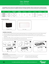
Burly - Round Bulkhead
Model: SBR14W
Installation Instructions
All installations must be carried out by a qualified electrician following local regulations. Make sure that the power is switched off before
installation. Please read and follow the ‘Installation instructions’ and ‘Safety instructions’ sections carefully before commencing installation.
Installation of this model can change from time to time please read instructions every time before installation. For detailed specification, please go to our website eurotechlighting.co.nz
Code: Colour: Dimensions
(mm):
Double
Insulated: IP Rating: Kelvins: Lumens: Material: Wattage:
SBR14W White 282Ø x 85 Ye s IP65 4000K 1200lm Polycarbonate 14W
For detailed specification, please go to our website eurotechlighting.co.nz
Product Information
Product Visual Dimensions
Saftey Instructions
Read these instructions carefully before commencing installation.
1. The light source contained in this luminaire shall only be replaced by the manufacturer or this service
agent or a similar qualified person.
2. This LED luminaire must be installed by a licensed electrician ONLY following all local regulations.
3. Ensure that the cables will not be squeezed or damaged by sharp edges.
4. Clean the light with a soft cloth and a standard PH-neutral detergent.
5. Misuse of/or changes to the appliance shall void all warranties.
6. Do not install on a surface that is not suitable or deformed.
7. Do not install on or above a surface with a high temperature.
8. There should not be any materials that are corrosive, explosive.
4
Installation Instructions
1. Remove the front diffuser from the base by removing the three diffuser fixing screws and pulling away from the base tray.
2. Loosen but do not remove the gear tray retaining screws. Adjust the position of the gear tray to align the hole in the keyhole slots with the
retaining screws. Remove the gear tray from the base.
3. Select a suitable cable entry point provided or drill out a hole in the base.
4. Position and fix the base to a suitable solid surface using the screws provided. Feed the supply cable into the luminaire through a previously selected hole
ensuring that the aperture is smooth or use a grommet where possible. Note:If using knock out hole on the side apply silicon to the joint or use IP65 cable
gland.
5. Terminate the supply cable into the terminal block mounted on the underside of the gear tray ensuring that the correct polarity is observed. All conductors
must be fully sleeved and insulated.
6. Dress any cables away from the edges of the luminaire and re-align the gear tray. Refit the gear tray using the retaining screws.
7. Re-fit the front diffuser to the base using the three diffuser fixing screws. Restore the mains power supply, switch on and test for satisfactory operation.
31 2
7
5 6

