3M DBI-SALA® FlexiGuard™ C-Frame System, Adjustable Height 8517705, 1 ea User manual
- Type
- User manual
Page is loading ...
Page is loading ...
Page is loading ...
Page is loading ...
Page is loading ...
Page is loading ...
Page is loading ...

8
12
A
B
A
AB
3
4
5
1
2
3
4
1
2
5
8517701, 8517703, 8517705,
8517707, 8517709, 8517711,
8517713
8530842, 8530843, 8530844,
8530845
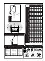
30° MA X
SAFE WORKING
ANGLE FROM
TROLLEY ANCHOR
POINTS
WHEEL KIT OPTIONS MA Y VA RY.
2
2

FORM NO: 5908278 REV: A
9
SAFETY INFORMATION
Please read, understand, and follow all safety information contained in these instructions prior to the use of this Flexiguard System.
FAILURE TO DO SO COULD RESULT IN SERIOUS INJURY OR DEATH.
These instructions must be provided to the user of this equipment. Retain these instructions for future reference.
Intended Use:
This Flexiguard System is intended for use as part of a complete fall protection or rescue system.
Use in any other application including, but not limited to, material handling, recreational or sports related activities, or other activities not described in
the User Instructions, is not approved by 3M and could result in serious injury or death.
This system is only to be used by trained users in workplace applications.
! WARNING
This Flexiguard System is part of a personal fall protection or rescue system. It is expected that all users be fully trained in the safe installation and
operation of the complete system. Misuse of this system could result in serious injury or death. For proper selection, operation, installation,
maintenance, and service, refer to all Product Instructions and all manufacturer recommendations, see your supervisor, or contact 3M Technical Service.
• To reduce the risks associated with transporting a Flexiguard system which, if not avoided, could result in serious injury or death:
- Ensure the system is properly secured or congured prior to transport. Refer to the User Instructions for detailed transportation requirements.
- Only transport below 5 mph (8 km/h) and at inclines of 10° or less, or as outlined in the User Instructions.
- Ensure the system will not contact overhead objects or electrical hazards while transporting or in use.
• To reduce the risks associated with working with a Flexiguard system which, if not avoided, could result in serious injury or death:
- Inspect all components of the system before each use, at least annually, and after any fall event, in accordance with the User Instructions.
- If inspection reveals an unsafe or defective condition, remove the system from service and repair or replace according to the User Instructions.
- Any system that has been subject to fall arrest or impact force must be immediately removed from service. Refer to the User Instructions or
contact 3M Fall Protection.
- The substrate or structure on which the system is attached/positioned must be able to sustain the static loads specied for the system in the
orientations permitted in the User Instructions or Installation Instructions.
- Do not exceed the number of allowable users as per the User Instructions.
- Never attach to a system until it is fully assembled, positioned, adjusted, and installed. Do not adjust the system while a user is attached.
- Never work outside the safe work area as dened by the User Instructions.
- Do not connect to the system while it is being transported or installed.
- Always maintain 100% tie-off when transferring between anchor points on the system.
- Use caution when installing, using, and moving the system as moving parts may create potential pinch points.
- Ensure proper lockout/tagout procedures have been followed when applicable.
- Only connect fall protection subsystems to the designated anchorage connection point on the system.
- When drilling holes for assembly or installation of the system, ensure no electric lines, gas lines, or other critical materials or equipment will be
contacted by the drill.
- Ensure that fall protection systems/subsystems assembled from components made by different manufacturers are compatible and meet the
requirements of applicable standards, including the ANSI Z359 or other applicable fall protection codes, standards, or requirements. Always
consult a Competent or Qualied Person before using these systems.
• To reduce the risks associated with working at heights which, if not avoided, could result in serious injury or death:
- Ensure your health and physical condition allow you to safely withstand all of the forces associated with working at height. Consult with your
doctor if you have any questions regarding your ability to use this equipment.
- Never exceed allowable capacity of your fall protection equipment.
- Never exceed maximum free fall distance of your fall protection equipment.
- Do not use any fall protection equipment that fails pre-use or other scheduled inspections, or if you have concerns about the use or suitability
of the equipment for your application. Contact 3M Technical Services with any questions.
- Some subsystem and component combinations may interfere with the operation of this equipment. Only use compatible connections. Consult
3M prior to using this equipment in combination with components or subsystems other than those described in the User Instructions.
- Use extra precautions when working around moving machinery (e.g. top drive of oil rigs) electrical hazards, extreme temperatures, chemical
hazards, explosive or toxic gases, sharp edges, or below overhead materials that could fall onto you or the fall protection equipment.
- Use Arc Flash or Hot Works devices when working in high heat environments.
- Avoid surfaces and objects that can damage the user or equipment.
- Ensure there is adequate fall clearance when working at height.
- Never modify or alter your fall protection equipment. Only 3M or parties authorized in by 3M may make repairs to the equipment.
- Prior to use of fall protection equipment, ensure a rescue plan is in place which allows for prompt rescue if a fall incident occurs.
- If a fall incident occurs, immediately seek medical attention for the fallen worker for the worker who has fallen.
- Do not use a body belt for fall arrest applications. Use only a Full Body Harness.
- Minimize swing falls by working as directly below the anchorage point as possible.
- If training with this device, a secondary fall protection system must be utilized in a manner that does not expose the trainee to an unintended
fall hazard.
- Always wear appropriate personal protective equipment when installing, using, or inspecting the device/system.
EN

10
;
Prior to installation and use of this equipment, record the product identification information from the ID label in the
Inspection and Maintenance Log (Table 2) at the back of this manual.
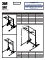
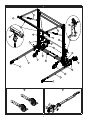
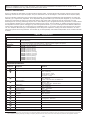
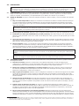
PRODUCT DESCRIPTION:
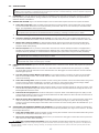
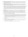
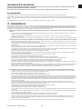
Figure 1 illustrates the Flexiguard
®
C-Frame Fall Arrest System (FAS). C-Frame FAS are fall protection systems with overhead
anchorage connections for up to two people. They are intended for use as anchorages in a Personal Fall Arrest System (PFAS).
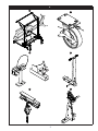
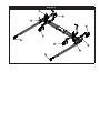
Figure 2 illustrates components of the C-Frame FAS. See Table 1 for component identication and specications. A Trolley Rail
assembly (A) is supported by adjustable & non-adjustable Upright Assemblies (B) and Trolley Rail Supports (C). Four-Wheeled
Trolleys (D) travel back and forth in the Trolley Rail Halves. Each Trolley has a connection point for connection of a Self-
Retracting Device or Energy Absorbing Lanyard. The C-Frame Bases (E) are equipped with swiveling Pneumatic or Caster Wheels
(F) and Transport Handles (G) for transporting and positioning the system. The Drive Mech (H) enables raising and lowering of
the adjustable C-Frame systems. Outriggers (I) with locking Caster Wheels (J) or non-swiveling Pneumatic Wheels stabilize the
system during transport and use. Leveling Jacks (K) and Bubble Levels (L) are used to level the system and prevent roll during
use. The Transport Wheels Kit (M) is sold separately and is designed to replace the existing front caster wheels for use when
towing the system across long distances. The Tow Bar (N) is sold separately and enables transportation of the C-Frame FAS with
a vehicle.
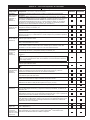
Table 1 – Specications
Performance Specications:
Capacity: 2 Trolleys per Trolley Rail: 1 Person per Trolley with a combined weight (clothing, tools, etc.) less than or equal to
310 lbs (140.6 kg).
Anchorage: The structure to which the Anchorage Connector is attached must sustain loads applied in the directions permitted
by the Fall Arrest System of at least 3,600 lbs (1,633 kg) plus the weight of the system.
Dimensions: See Figure 1 for the dimensions of each C-Frame FAS model.
Weight: 8517701: 1,650 lbs (749 kg)
8517703: 1,970 lbs (893 kg)
8517705: 2,097 lbs (951 kg)
8517707: 2,104 lbs (954 kg)
8517709: 2,232 lbs (1,012 kg)
8517711: 2,238 lbs (1,015 kg)
8517713: 2,366 lbs (1,073 kg)
8530842: 1,450 lbs (658 kg)
8530843: 1,500 lbs (680 kg)
8530844: 1,600 lbs (725 kg)
8530845: 1,650 lbs (749 kg)
Component Specications:
Figure 2
Reference Component Materials
A
Trolley Rail Aluminum
B
Upright Assembly Tubes - Aluminum
Plates - Aluminum
Carriage Housing - Steel
Carriage Rollers - Nylatron
Chain Roller - Acetal
C
Trolley Rail Support Tubes - Aluminum
Bars - Aluminum
Gussets - Stainless Steel with EPDM cover
D
4-Wheeled Trolley
Wheels - Nylon
Bearings - Steel
5/8” Connection Eye - Stainless Steel
E
C-Frame Base Tubes - Aluminum
Plates - Aluminum
F
Pneumatic Wheels Rubber - Foam-lled
G
Transport Handles Tube - Steel
Handles - Rubber
H
Drive Mech Steel; aluminum
I
Outrigger Aluminum
J
Caster Wheels
Wheels - Urethane
Mounting Tube - Aluminum.
K
Leveling Jacks Steel
L
Bubble Level Plastic
M
Transport Wheels Kit - 8530841 Rubber - Foam-lled
N
Tow Bar Kit - 8518243 (sold separately) Aluminum; steel
1
1 Qualied Person: A person with a recognized degree of professional certicate and with extensive knowledge, training, and experience in the fall protection and rescue eld
who is capable of designing, analyzing, evaluating, and specifying fall protections and rescue systems to the extent required by OSHA and other applicable standards.

11
1.0 PRODUCT APPLICATION
1.1 PURPOSE: Flexiguard
™
Anchorage Systems are designed to provide anchorage connection points for a Personal Fall Arrest
System (PFAS).
1.2 SUPERVISION: Installation of this equipment must be supervised by a Qualied Person
1
. Use of this equipment must be
supervised by a Qualied Person
1
.
1.3 TRAINING: This equipment must be installed and used by persons trained in its correct application. This manual is to be
used as part of an employee training program as required by OSHA. It is the responsibility of the users and installers of
this equipment to ensure they are familiar with these instructions, trained in the correct care and use of this equipment,
and are aware of the operating characteristics, application limitations, and consequences of improper use of this
equipment.
1.4 RESCUE PLAN: When using this equipment and connecting subsystem(s), the employer must have a rescue plan and
the means at hand to implement and communicate that plan to users, authorized persons
2
, and rescuers
3
. A trained, on-
site rescue team is recommended. Team members should be provided with the equipment and techniques to perform a
successful rescue. Training should be provided on a periodic basis to ensure rescuer prociency.
1.5 INSPECTION FREQUENCY:
The Flexiguard
Anchorage System
shall be inspected by the user before each use and,
additionally, by a competent person other than the user at intervals of no longer than one year.
4
Inspection procedures are
described in the “Inspection and Maintenance Log”. Results of each Competent Person inspection should be recorded on
copies of the “Inspection and Maintenance Log”.
1.6 AFTER A FALL: If the Flexiguard Anchorage System is subjected to the forces of arresting a fall, it must be removed from
the eld of service immediately and replaced or inspected by an Authorized 3M Representative.
2.0 SYSTEM CONSIDERATIONS
2.1 ANCHORAGE: Structure on which the Flexiguard Anchorage System is placed or mounted must meet the Anchorage
specications dened in Table 1.
2.2 PERSONAL FALL ARREST SYSTEM: Figure 1 illustrates the application of this Flexiguard Anchorage System. Personal
Fall Arrest Systems (PFAS) used with the system must meet applicable OSHA, ANSI, state, and federal requirements.
The PFAS shall incorporate a Full Body Harness and Self-Retracting Device (SRD) with a 900 lb (4 kN) Average Arresting
Force.
2.3 FALL PATH AND SRL LOCKING SPEED: A clear path is required to assure positive locking of an SRL. Situations which
do not allow for an unobstructed fall path should be avoided. Working in confined or cramped spaces may not allow the
body to reach sufficient speed to cause the SRL to lock if a fall occurs. Working on slowly shifting material, such as sand
or grain, may not allow enough speed buildup to cause the SRL to lock.
2.4 HAZARDS: Use of this equipment in areas with environmental hazards may require additional precautions to prevent
injury to the user or damage to the equipment. Hazards may include, but are not limited to: heat, chemicals, corrosive
environments, high voltage power lines, explosive or toxic gases, moving machinery, sharp edges, or overhead materials
that may fall and contact the user or Personal Fall Arrest System.
2.5 FALL CLEARANCE: There must be sufcient clearance below the user to arrest a fall before the user strikes the ground
or other obstruction. Fall Clearance is dependent on the following factors:
• Deceleration Distance • Worker Height • Elevation of Anchorage Connector
• Free Fall Distance • Movement of Harness Attachment Element • Connecting Subsystem Length
See the Personal Fall Arrest System manufacturer’s instructions for specics regarding Fall Clearance calculation.
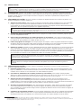
2.6 SWING FALLS: Swing Falls occur when the anchorage point is not directly above the point where a fall occurs (see).
The force of striking an object in a swing fall may cause serious injury or death. Minimize swing falls by working as
directly below the anchorage point as possible. Do not permit a swing fall if injury could occur. Swing falls will signicantly
increase the clearance required when a Self-Retracting Device or other variable length connecting subsystem is used.
2.7 SHARP EDGES: Avoid working where Lifeline or Lanyard components of the Personal Fall Arrest System (PFAS) can
contact or abrade against unprotected sharp edges (see Figure 4). Where contact with a sharp edge is unavoidable, cover
the edge with protective material (A).
2.8 COMPONENT COMPATIBILITY: 3M equipment is designed for use with 3M approved components and subsystems
only. Substitutions or replacements made with non-approved components or subsystems may jeopardize compatibility of
equipment and may effect the safety and reliability of the complete system.

12
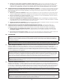
2.9 CONNECTOR COMPATIBILITY: Connectors are considered to be compatible with connecting elements when they
have been designed to work together in such a way that their sizes and shapes do not cause their gate mechanisms to
inadvertently open regardless of how they become oriented. Contact 3M if you have any questions about compatibility.
Connectors (hooks, carabiners, and D-rings) must be capable of supporting at least 5,000 lbs. (22.2 kN). Connectors
must be compatible with the anchorage or other system components. Do not use equipment that is not compatible.
Non-compatible connectors may unintentionally disengage (see Figure 5). Connectors must be compatible in size, shape,
and strength. If the connecting element to which a snap hook or carabiner attaches is undersized or irregular in shape, a
situation could occur where the connecting element applies a force to the gate of the snap hook or carabiner (A). This force
may cause the gate to open (B), allowing the snap hook or carabiner to disengage from the connecting point (C).
Self-locking snap hooks and carabiners are required by ANSI Z359 and OSHA.
2.10 MAKING CONNECTIONS: Snap hooks and carabiners used with this equipment must be self-locking. Ensure all
connections are compatible in size, shape and strength. Do not use equipment that is not compatible. Ensure all
connectors are fully closed and locked.
3M connectors (snap hooks and carabiners) are designed to be used only as specied in each product’s user’s instructions.
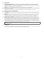
See Figure 6 for examples of inappropriate connections. Do not connect snap hooks and carabiners:
A. To a D-ring to which another connector is attached.
A. In a manner that would result in a load on the gate. Large throat snap hooks should not be connected to standard
size D-rings or similar objects which will result in a load on the gate if the hook or D-ring twists or rotates, unless the
snap hook complies is equipped with a 3,600 lb (16 kN) gate. Check the marking on your snap hook to verify that it
is appropriate for your application.
B. In a false engagement, where features that protrude from the snap hook or carabiner catch on the anchor, and
without visual conrmation seems to be fully engaged to the anchor point.
C. To each other.
D. Directly to webbing or rope lanyard or tie-back (unless the manufacturer’s instructions for both the lanyard and
connector specically allows such a connection).
E. To any object which is shaped or dimensioned such that the snap hook or carabiner will not close and lock, or that
roll-out could occur.
F. In a manner that does not allow the connector to align properly while under load.

13
3.0 INSTALLATION
;
IMPORTANT: Installation of the Flexiguard
®
C-Frame Fall Arrest System (FAS) must be supervised by a Qualied Person
1
. The
installation must be certied by a Competent Person as meeting the criteria for a Certied Anchorage, or that it is capable of supporting
the potential forces that could be encountered during a fall.
1
3.1 PLANNING: Plan your fall protection system prior to installation of the Flexiguard C-Frame FAS. Account for all factors
that may affect your safety before, during, and after a fall. Consider all requirements, limitations, and specications
dened in Section 2 and Table 1.
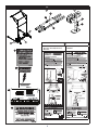
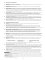
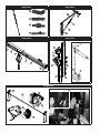
3.2 MOVING THE SYSTEM: Figure 7 illustrates transport of the C-Frame FAS. Prepare and move the system as follows:
1. Lower the Trolley Rail: Crank the Hand Crank Chain Drives counterclockwise until the Trolley Rail is fully lowered.
The two Hand Crank Chains Drive are synchronized by a Connector Tube so it is not necessary to crank both Chain
Drives. (For adjustable C-frame systems only.)
;
Do not raise or lower the Trolley Rail while in use. Vertical movement of the Trolley Rail at the time of a fall
may impede proper operation of the attached Fall Arrest system(s), resulting in serious injury or death.
2. Raise the Leveling Jacks: Crank the handle on each Leveling Jack until the jack is fully raised.
3. Unlock the Outrigger Caster Wheels (if present): For each Caster Wheel: Flip the Brake Pedal parallel to the
ground to release the Wheel Brake. Pull out and rotate the Caster Swivel Lock 90° to allow the wheel to caster 360°.
4. Release the Transport Handles: For Each Transport Handle: Remove the Detent Pin from Push Bar Mounting
Bracket. Pivot the Transport Handle downward. Reinsert the Detent Pin above the tube to prevent pivoting of the
Transport Handle while pushing.
5. Move the System: Push or pull the C-Frame FAS to the work area with the Transport Handles. If equipped with a
Tow Bar, the C-Frame FAS can be transported longer distances with a Tow Vehicle with a Pintle or similar hitch. The
Transport Wheel Kit (8530841) is recommended for transporting the system when using the Tow Bar (8518243).
;
Never transport the Flexiguard C-Frame Fall Arrest System on slopes greater than 5°. Excessive slopes may
cause system tip-overs resulting in serious injury or death.
;
When transporting the Flexiguard C-Frame Fall Arrest System, be aware of overhead obstructions and electrical
hazards which may result in serious injury or death.
3.3 PREPARING THE SYSTEM: Figure 8 illustrates preparation of the C-Frame for work. Position and prepare the system as
follows:
1. Position the C-Frame: Position the C-Frame on a at surface within the Safe Work Area (see Figure 3). Ideally
the Trolley Rail should be centered over the intended work area. Outriggers can extend under the serviced vehicle if
sufcient gap is present.
2. Lock the Outrigger Caster Wheels (if present): For each Caster Wheel: Push down on either end of the Brake
Pedal to lock the Wheel Brake. Pull out and rotate the Caster Swivel Lock 90° to lock the caster and prevent the
wheel from swiveling.
3. Lower the Leveling Jacks: Crank the handle on each Leveling Jack clockwise until the Jack Pad contacts the ground
and then crank the handle an additional 5 revolutions. If surface is uneven adjust each jack accordingly. Bubble
Levels are mounted on the C-Frame Base near each jack to assist in leveling the system.
4. Secure the Transport Handles: For Each Transport Handle: Pivot the Transport Handle up until the pin holes in the
Push Bar Mounting Bracket align with the pin holes in the Corner Tube. Insert the Detent Pin through all holes in the
Mounting Bracket and Corner Tube.
5. Install Fall Arrest Equipment: A Fall Arrest subsystem is required. Attach a Self-Retracting Device (SRD) to each
of the 4-Wheeled Trolleys. Tag Lines lines should be attached to the SRD Lifelines to allow retrieval and connection of
the lifeline after the Trolley Rail is raised.
6. Raise the Trolley Rail (Adjustable Systems Only): Crank the Hand Crank on one of the Hand Crank Chain Drives
until the Trolley Rail is at sufcient height to ensure a Safe Work Area (see Figure 3). Raise the Trolley Rail high
enough to ensure the Working Angle of the lifeline does not exceed 30° when working within the allowable 6 ft. (1.8
m) Work Radius.
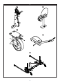
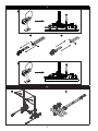
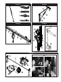
3.4 INSTALLING THE TRANSPORT WHEELS KIT (8530841): The Transport Wheels Kit may be installed for transporting
the C-Frame FAS long distances and in coordination with the Tow Bar Kit (8518243). See Figure 9 for reference. To install
the Transport Wheels Kit:
1. Lower the Leveling Jacks: Crank the handle on each Leveling Jack clockwise until the Jack Pad contacts the ground
and both of the front Caster Wheels are off the ground.
2. Remove the Caster Wheel Assembly: Remove the 1/2” bolt from the Outriggers on both sides of the system and
then remove the Caster Wheel Assembly.
3. Insert the Transport Wheel Assemblies: Insert the 8530841 Transport Wheel Assembly into the Outriggers on
1 Qualied Person: A person with a recognized degree of professional certicate and with extensive knowledge, training, and experience in the fall protection
and rescue eld who is capable of designing, analyzing, evaluating, and specifying fall protections and rescue systems to the extent required by OSHA and other
applicable standards

14
both sides of the system. Bolt the Transport Wheels into place using the 1/2” hardware. Torque the hardware to 60
ft*lbs (81 N*m).
4. Raise the Leveling Jacks: Raise each Leveling Jack again so that the wheels of the C-Frame FAS are resting on the
ground.
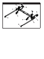
3.5 INSTALLING THE TOW BAR KIT (8518243): The Tow Bar Kit may be installed for transporting the C-Frame FAS using
the hitch of a vehicle. See Figure 10 for reference. To install the Tow Bar Kit:
1. Center the Tow Bar on the Base: Center the Tow Bar on the C-Frame Base. If necessary, move the label plate of
the C-Frame FAS to either end of the system.
2. Attach the Tow Bar to the Base: Fasten the clamps of the Tow Bar to the cross tubes of the C-Frame Base using
the 3/8” hardware. Torque the hardware to 45 ft*lbs (61 N*m).
4.0 USE
;
Consult your doctor if there is any reason to doubt your tness to safely absorb the shock from a fall arrest or
suspension. Age and tness seriously affect a worker’s ability to withstand falls. Pregnant women or minors must not
use DBI-SALA equipment unless in an emergency situation.
;
Never exceed the Capacity maximums specied in Table 1. Exceeding the stated capacity could collapse or tip the
system, resulting in serious injury or death.
4.1 BEFORE EACH USE: Verify that your work area and Personal Fall Arrest System (PFAS) meet all criteria dened in
Section 2 and a formal Rescue Plan is in place. Inspect the C-Frame Fall Arrest System per the ‘User’ inspection points
dened on the “Inspection and Maintenance Log” (Table 2). If inspection reveals an unsafe or defective condition, do not
use the C-Frame FAS. Remove the system from service and contact Capital Safety regarding replacement or repair.
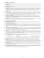
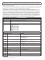
;
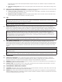
Figure 3 illustrates the Safe Work Area for the C-Frame Fall Arrest System. The gray shading on the table
designates safe working distances where the angle of the Lifeline is less than or equal to 30° from vertical and the
Horizontal Distance (H) from the anchorage connection point is less than or equal to 6 ft (1.82 m). NEVER work at a
Horizontal Distance (H) and Vertical Distance (V) that results in a calculated Vertical Fall Distance (F) exceeding the
gray shaded values on the table in Figure 3.
;
Never use the C-Frame Fall Arrest System for Fall Protection without the Outriggers securely installed. Use of the
C-Frame without the Outriggers can tip the system resulting in injury or death.
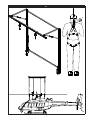
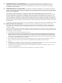
4.2 FALL ARREST CONNECTIONS: Figure 11 illustrates the C-Frame and its Fall Arrest Connections. Users must wear
a Full Body Harness connected to the C-Frame Trolley Rail with a Fall Arrest subsystem (Self-Retracting Device). The
Trolley Rail is equipped with two Four-Wheel Trolleys that travel back-and-forth inside the Rail Halves. One Self-Retracting
Device (SRD) can be connected to each Four-Wheel Trolley. Connect the lifeline on the SRD to the back Dorsal D-Ring on
the Harness. A Tag Line can be attached to the SRD Lifeline and used to retrieve the lifeline for connection to the user’s
harness.
;
When transferring between SRDs, always maintain 100% tie-off to ensure fall arrest protection in the event of a fall.
;
No more than one person, meeting the Capacity requirements specied in Table 1, shall be attached to the Glide
Four-Wheel Trolley.
;
Inappropriate or incompatible connections between components of the Personal Fall Arrest System (PFAS) may
result in serious injury or death. See Section 2 for details regarding connector compatibility and safe connections.
5.0 INSPECTION
5.1 INSPECTION FREQUENCY: The C-Frame FAS must be inspected at the intervals dened in Section 1. Inspection
procedures are described in the “Inspection and Maintenance Log” (Table 2). Inspect all other components of the Fall
Protection System per the frequencies and procedures dened in the manufacturer’s instructions.
5.2 DEFECTS: If inspection reveals an unsafe or defective condition, remove the C-Frame FAS from service immediately. Do
not attempt to repair the Fall Arrest System.
5.3 PRODUCT LIFE: The functional life of the C-Frame FAS is determined by work conditions and maintenance. As long as
the product passes inspection criteria, it may remain in service.
6.0 MAINTENANCE, SERVICING, STORAGE
6.1 CLEANING: Periodically clean the metal components of the C-Frame FAS with a soft brush, warm water, and a mild soap
solution. Ensure parts are thoroughly rinsed with clean water.
6.2 SERVICE: Only 3M or parties authorized in writing by 3M may make repairs to this equipment. If the Flexiguard System
has been subject to fall force or inspection reveals an unsafe or defective conditions, remove the system from service and
contact 3M regarding replacement or repair.

15
6.3 STORAGE AND TRANSPORT: The C-Frame FAS is designed to be stored outdoors during normal weather conditions.
If the weather is severe, it is recommended to store the system in an area that protects against damage to the system.
Store the C-Frame FAS and associated fall protection equipment in a cool, dry, clean environment out of direct sunlight.
Avoid areas where chemical vapors may exist. Thoroughly inspect components after extended storage. If the system is
transported long distances, it should be disassembled and all components secured and protected from severe conditions
during transport.
;
When transporting the C-Frame FAS, do not exceed transport speeds of 5.0 mph (8.0 km/h).
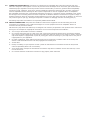
7.0 LABELS
Figure 12 illustrates labels on the C-Frame FAS. All labels must be present and should be replaced if they are not fully
legible.

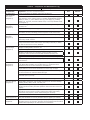
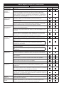
Table 2 – Inspection and Maintenance Log
Inspection Date: Inspected By:
Components: Inspection: (See Section 1 for Inspection Frequency) User
Competent
Person
Tie-Back Cable
and Turnbuckle
Assemblies
(Diagram 1)
Inspect Turnbuckles for damage and proper adjustment.
Check Tie-Back Cables for slack. Cables must be tight enough to apply
slight pressure on the system structure, DO NOT OVERTIGHTEN. Inspect
cables, for kinks (1), cut or broken wires (2), bird-caging (3), welding
splatter (4), corrosion, chemical contact areas, or severely abraded areas.
(see Diagram 1).
Rail Support
Assemblies
(Diagram 2)
Check Rails Supports (1) for structural defects or damage including bends,
corrosion, etc.
Inspect fasteners (2) on Rail Supports to ensure they are tight.
Visually inspect the Gussets (3) for straightness. Ensure there is no visible
deformation or bend, indicating previous exposure to fall arrest forces.
Trolley Rail
Assembly
(Diagram 3)
Visually inspect fasteners (1) on the Trolley Rail to ensure they are tight.
Inspect the Rail Track (2) for structural defects. Rail Track must be straight
without any bends or dents.
Visually inspect the Trolley Four-Wheel Trolleys (3) for damage to the
trolley and excessive wheel wear. Ensure the Trolleys roll freely in Trolley
Rail and the wheels are securely attached.
Upright Assemblies
and Carriages
(Diagram 4)
Inspect the Vertical Uprights (1) and Carriages (2) for defects or structural
damage including bends, corrosion, etc.
Inspect Carriage Rollers (3) for cracks, chips, or excessive wear.
;
Roller Grease Zerks (5) should be greased monthly, or more
frequently under extreme environmental conditions or heavy use.
Inspect fasteners on Uprights and Carriages to ensure they are tight.
;
Do not adjust Threaded Rods (4). They are preset by the
manufacturer.
Vertical Drive
Mechanisms
(Diagram 5)
Inspect the Brake Wear Indicators (1) while lowering the Work Platform.
If the Brake Wear Indicator is in the Red zone (2), remove the Drive
Mechanism from service and contact the manufacturer.
Inspect fasteners on the Drive Mechanism to ensure they are tight.
Visually inspect the Drive Connector Bar (3). The bar should be straight
and the connectors on each end should be tight.
Inspect the Drive Chain (4) for slack. Deection of the chain should not be
more than 1/2 in (13 mm).
Lubricate the Drive Chain with light oil (5) and grease Bearings.
Base and Wheels
(Diagram 6)
Inspect Base, Outriggers, and Tow Bar (if present) for structural damage
including bends, dents, cracks, corrosion, etc.
Inspect the Leveling Jacks (3) for damage or deformities. Ensure crank
handles operate smoothly and that operation raises and lowers each Jack
properly.
Inspect the Pneumatic Wheels (1) and Caster Wheels (2) for damage or
deformities. Ensure wheels roll freely and that the brakes and locking
mechanism work properly. Grease wheel bearings if necessary.
Check for ats in the wheels.
Labels (Figure 12) Verify that all labels are securely attached and are legible (see ‘Labels’).
PFAS and Other
Equipment
Additional Personal Fall Arrest System (PFAS) equipment (harness, Self-
Retracting Device, etc) that are used with the Flexiguard System should be
installed and inspected per the manufacturer’s instructions.

Table 2 – Inspection and Maintenance Log
Inspection Date: Inspected By:
Serial Number(s): Date Purchased:
Model Number: Date of First Use:
Corrective Action/Maintenance: Approved By:
Date:
Corrective Action/Maintenance: Approved By:
Date:
Corrective Action/Maintenance: Approved By:
Date:
Corrective Action/Maintenance: Approved By:
Date:
Corrective Action/Maintenance: Approved By:
Date:
Corrective Action/Maintenance: Approved By:
Date:
Corrective Action/Maintenance: Approved By:
Date:
Corrective Action/Maintenance: Approved By:
Date:
Corrective Action/Maintenance: Approved By:
Date:
Corrective Action/Maintenance: Approved By:
Date:
Corrective Action/Maintenance: Approved By:
Date:
Corrective Action/Maintenance: Approved By:
Date:
Corrective Action/Maintenance: Approved By:
Date:
Corrective Action/Maintenance: Approved By:
Date:
Corrective Action/Maintenance: Approved By:
Date:
Corrective Action/Maintenance: Approved By:
Date:
Corrective Action/Maintenance: Approved By:
Date:
Corrective Action/Maintenance: Approved By:
Date:
Corrective Action/Maintenance: Approved By:
Date:
Corrective Action/Maintenance: Approved By:
Date:
Corrective Action/Maintenance: Approved By:
Date:
Page is loading ...
Page is loading ...
Page is loading ...
Page is loading ...
Page is loading ...
Page is loading ...
Page is loading ...
Page is loading ...
Page is loading ...
Page is loading ...
Page is loading ...
Page is loading ...
Page is loading ...
Page is loading ...
Page is loading ...
Page is loading ...
Page is loading ...
Page is loading ...
Page is loading ...
Page is loading ...
Page is loading ...
Page is loading ...
Page is loading ...
Page is loading ...
Page is loading ...

GARANTIE INTERNATIONALE DU PRODUIT, RECOURS LIMITÉ
ET LIMITATION DE RESPONSABILITÉ
GARANTIE : CE QUI SUIT REMPLACE TOUTES LES GARANTIES OU CONDITIONS, EXPRESSES OU
IMPLICITES, Y COMPRIS LES GARANTIES OU LES CONDITIONS IMPLICITES RELATIVES À LA QUALITÉ
MARCHANDE ET À L’ADAPTATION À UN USAGE PARTICULIER.
Sauf disposition contraire de la loi, les produits de protection antichute 3M sont garantis contre tout défaut
de fabrication en usine et de matériaux pour une période d’un (1) an à compter de la date d’installation ou
de la première utilisation par le propriétaire initial.
RECOURS LIMITÉ : Moyennant un avis écrit à 3M, 3M réparera ou remplacera tout produit présentant un
défaut de fabrication en usine ou de matériaux, tel que déterminé par 3M. 3M se réserve le droit d’exiger le
retour du produit dans ses installations afi n d’évaluer la réclamation de garantie. Cette garantie ne couvre
pas les dommages au produit résultant de l’usure, d’un abus ou d’une mauvaise utilisation, les dommages
subis pendant l’expédition, le manque d’entretien du produit ou d’autres dommages en dehors du contrôle
de 3M. 3M jugera seul de l’état du produit et des options de garantie.
Cette garantie s’applique uniquement à l’acheteur initial et est la seule garantie applicable aux produits de
protection antichute de 3M. Veuillez communiquer avec le service à la clientèle de 3M de votre région pour
obtenir de l’aide.
LIMITATION DE RESPONSABILITÉ : DANS LES LIMITES PRÉVUES PAR LES LOIS LOCALES, 3M NE SERA
TENU POUR RESPONSABLE DE TOUT DOMMAGE INDIRECT, ACCESSOIRE, SPÉCIFIQUE OU CONSÉCUTIF
INCLUANT, SANS S’Y LIMITER, LA PERTE DE PROFIT, LIÉS DE QUELQUE MANIÈRE AUX PRODUITS, QUELLE
QUE SOIT LA THÉORIE LÉGALE INVOQUÉE.
GARANTÍA GLOBAL DEL PRODUCTO, REPARACIONES LIMITADAS
Y LIMITACIÓN DE RESPONSABILIDAD
GARANTÍA: EL SIGUIENTE TEXTO SIRVE A MODO DE GARANTÍA O CONDICIÓN, EXPLÍCITA O IMPLÍCITA,
E INCLUYE LAS GARANTÍAS O CONDICIONES IMPLÍCITAS DE COMERCIABILIDAD O APTITUD PARA UN
PROPÓSITO ESPECÍFICO.
A menos que las leyes locales indiquen lo contrario, los productos de protección contra caídas 3M tienen
garantía por defectos de fábrica en la mano de obra y en los materiales durante un período de un año desde
la fecha de instalación o desde el primer uso del propietario original.
REPARACIONES LIMITADAS: 3M reparará o reemplazará un producto si determina que tiene un defecto
de fábrica en la mano de obra o en los materiales y tras haber recibido una notifi cación por escrito sobre
el presunto defecto. 3M se reserva el derecho de exigir la devolución del producto a sus instalaciones
para evaluar los reclamos sobre la calidad. Esta garantía no cubre los daños ocasionados por el desgaste,
el abuso, el mal mantenimiento, o como consecuencia del traslado del producto, u otros daños ajenos al
control de 3M. 3M será el único capaz de determinar la condición del producto y las opciones de la garantía.
Esta garantía solo se aplica al comprador original y es la única garantía válida para los productos de
protección contra caídas 3M. Comuníquese con el departamento de servicio al cliente de 3M de su región
para obtener ayuda.
LIMITACIÓN DE RESPONSABILIDAD: EN LA MEDIDA PERMITIDA POR LAS LEYES LOCALES, 3M NO
SERÁ RESPONSABLE DE LOS DAÑOS INDIRECTOS, IMPREVISTOS, ESPECIALES O CONSECUENTES; ENTRE
ELLOS, LA PÉRDIDA DE INGRESOS RELACIONADOS DE CUALQUIER MANERA CON LOS PRODUCTOS,
INDEPENDIENTEMENTE DE LA TEORÍA JURÍDICA QUE SE PUDIERA INVOCAR.

USA
3833 SALA Way
Red Wing, MN 55066-5005
Toll Free: 800.328.6146
Phone: 651.388.8282
Fax: 651.388.5065
Brazil
Rua Anne Frank, 2621
Boqueirão Curitiba PR
81650-020
Brazil
Phone: 0800-942-2300
Mexico
Calle Norte 35, 895-E
Col. Industrial Vallejo
C.P. 02300 Azcapotzalco
Mexico D.F.
Phone: (55) 57194820
Colombia
Compañía Latinoamericana de Seguridad S.A.S.
Carrera 106 #15-25 Interior 105 Manzana 15
Zona Franca - Bogotá, Colombia
Phone: 57 1 6014777
Canada
260 Export Boulevard
Mississauga, ON L5S 1Y9
Phone: 905.795.9333
Toll-Free: 800.387.7484
Fax: 888.387.7484
EMEA (Europe, Middle East, Africa)
EMEA Headquarters:
Le Broc Center
Z.I. 1re Avenue - BP15
06511 Carros Le Broc Cedex
France
Phone: + 33 04 97 10 00 10
Fax: + 33 04 93 08 79 70
Australia & New Zealand
137 McCredie Road
Guildford
Sydney NSW 2161
Australia
Phone: +(61) 2 8753 7600
Toll-Free : 1800 245 002 (AUS)
Toll-Free : 0800 212 505 (NZ)
Fax: +(61) 2 8753 7603
Asia
Singapore:
1 Yishun Avenue 7
Singapore 768923
Phone: +65-6450 8888
Fax: +65-6552 2113
China:
38/F, Maxdo Center, 8 Xing Yi Rd
Shanghai 200336, P R China
Phone: +86 21 62753535
Fax: +86 21 52906521
Korea:
3M Koread Ltd
20F, 82, Uisadang-daero,
Yeongdeungpo-gu, Seoul
Phone: +82-80-033-4114
Fax: +82-2-3771-4271
Japan:
3M Japan Ltd
6-7-29, Kitashinagawa, Shinagawa-ku, Tokyo
Phone: +81-570-011-321
Fax: +81-3-6409-5818
WEBSITE:
3M.com/FallProtection
ISO
9001
FM534873
EU DECLARATION OF CONFORMITY:
3M.com/FallProtection/DOC
U.S. PRODUCT WARRANTY, LIMITED REMEDY
AND LIMITATION OF LIABILITY
WARRANTY: THE FOLLOWING IS MADE IN LIEU OF ALL WARRANTIES OR CONDITIONS, EXPRESS
OR IMPLIED, INCLUDING THE IMPLIED WARRANTIES OR CONDITIONS OF MERCHANTABILITY OR
FITNESS FOR A PARTICULAR PURPOSE.
Unless otherwise provided by applicable law, 3M fall protection products are warranted against factory
defects in workmanship and materials for a period of one year from the date of installation or fi rst use
by the original owner.
LIMITED REMEDY: Upon written notice to 3M, 3M will repair or replace any product determined by
3M to have a factory defect in workmanship or materials. 3M reserves the right to require product be
returned to its facility for evaluation of warranty claims. This warranty does not cover product damage
due to wear, abuse, misuse, damage in transit, failure to maintain the product or other damage beyond
3M’s control. 3M will be the sole judge of product condition and warranty options.
This warranty applies only to the original purchaser and is the only warranty applicable to 3M’s fall
protection products. Please contact 3M’s customer service department at 800-328-6146 or via email at
3MF[email protected] for assistance.
LIMITATION OF LIABILITY: TO THE EXTENT PERMITTED BY APPLICABLE LAW, 3M IS NOT
LIABLE FOR ANY INDIRECT, INCIDENTAL, SPECIAL OR CONSEQUENTIAL DAMAGES INCLUDING,
BUT NOT LIMITED TO LOSS OF PROFITS, IN ANY WAY RELATED TO THE PRODUCTS REGARDLESS
OF THE LEGAL THEORY ASSERTED.
-
 1
1
-
 2
2
-
 3
3
-
 4
4
-
 5
5
-
 6
6
-
 7
7
-
 8
8
-
 9
9
-
 10
10
-
 11
11
-
 12
12
-
 13
13
-
 14
14
-
 15
15
-
 16
16
-
 17
17
-
 18
18
-
 19
19
-
 20
20
-
 21
21
-
 22
22
-
 23
23
-
 24
24
-
 25
25
-
 26
26
-
 27
27
-
 28
28
-
 29
29
-
 30
30
-
 31
31
-
 32
32
-
 33
33
-
 34
34
-
 35
35
-
 36
36
-
 37
37
-
 38
38
-
 39
39
-
 40
40
-
 41
41
-
 42
42
-
 43
43
-
 44
44


3M DBI-SALA® FlexiGuard™ C-Frame System, Adjustable Height 8517705, 1 ea User manual
- Type
- User manual
Ask a question and I''ll find the answer in the document
Finding information in a document is now easier with AI
in other languages
Related papers
-
3M DBI-SALA® FlexiGuard™ Adjustable Height Box Frame System 8530288, 1 EA User manual
-
-
3M DBI-SALA® FlexiGuard™ Adjustable Height Jib 8530557, 1 EA Operating instructions
-
-
-
-
DBI-SALA DBI-SALA® FlexiGuard™ Sky Anchor System 8530152, 1 EA Operating instructions
-
-
-
3M DBI-SALA® Confined Space Portable Fall Arrest Post 8516996, 1 EA Operating instructions
Other documents
-
 SafeWaze 018-4000 Owner's manual
-
 FallTech 721530TD1 User manual
-
Klein Tools 87480 Operating instructions
-
 FallTech 727650LE User guide
-
Miller 475 User manual
-
Werner R210060 Owner's manual
-
Gleason Reel I-132 I-Beam Festoon System Installation guide
-
Gibraltar Mailboxes PALPP500W Installation guide
-
 BeamGrip Beam Trolley Owner's manual
-


