NEC WT600 Owner's manual

Category
Data projectors
Type
Owner's manual
WT600
Projector
Users Manual
ii
Safety Cautions
Precautions
Please read this manual carefully before using your NEC WT600
Projector and keep the manual handy for future reference. Your
serial number is located on the right side of your projector. Record
it here:
CAUTION
To turn off main power, be sure to remove the plug
from power outlet.
The power outlet socket should be installed as near to
the equipment as possible, and should be easily ac-
cessible.
CAUTION
TO PREVENT SHOCK, DO NOT OPEN THE CABI-
NET.
NO USER-SERVICEABLE PARTS INSIDE.
REFER SERVICING TO QUALIFIED NEC SERVICE
PERSONNEL.
This symbol warns the user that uninsulated voltage
within the unit may be sufficient to cause electrical shock.
Therefore, it is dangerous to make any kind of contact
with any part inside of the unit.
This symbol alerts the user that important information
concerning the operation and maintenance of this unit
has been provided.
The information should be read carefully to avoid prob-
lems.
WARNING
TO PREVENT FIRE OR SHOCK, DO NOT EXPOSE THIS
UNIT TO RAIN OR MOISTURE.
DO NOT USE THIS UNIT’S GROUNDED PLUG WITH AN
EXTENSION CORD OR IN AN OUTLET UNLESS ALL
THREE PRONGS CAN BE FULLY INSERTED.
DO NOT OPEN THE CABINET. THERE ARE HIGH-VOLT-
AGE COMPONENTS INSIDE. ALL SERVICING MUST BE
DONE BY QUALIFIED NEC SERVICE PERSONNEL.
DOC Compliance Notice
This Class B digital apparatus meets all requirements of the
Canadian Interference-Causing Equipment Regulations.
Acoustic Noise Information Ordinance-3. GSGV:
The sound pressure level is less than 70 dB (A) according
to ISO 3744 or ISO 7779.
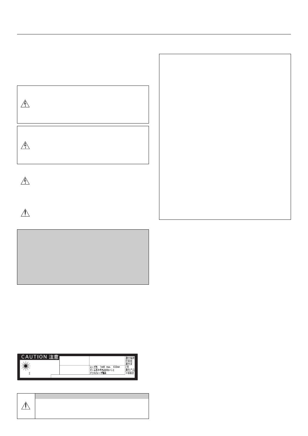
This label is on the side of the remote control.
RF Interference
WARNING
The Federal Communications Commission does not al-
low any modifications or changes to the unit EXCEPT
those specified by NEC Soluctions (America), Inc. in this
manual. Failure to comply with this government regula-
tion could void your right to operate this equipment. This
equipment has been tested and found to comply with
the limits for a Class B digital device, pursuant to Part 15
of the FCC Rules. These limits are designed to provide
reasonable protection against harmful interference in a
residential installation. This equipment generates, uses,
and can radiate radio frequency energy and, if not in-
stalled and used in accordance with the instructions, may
cause harmful interference to radio communications.
However, there is no guarantee that interference will not
occur in a particular installation. If this equipment does
cause harmful interference to radio or television recep-
tion, which can be determined by turning the equipment
off and on, the user is encouraged to try to correct the
interference by one or more of the following measures:
Reorient or relocate the receiving antenna.
Increase the separation between the equipment and re-
ceiver.
Connect the equipment into an outlet on a circuit different
from that to which the receiver is connected.
Consult the dealer or an experienced radio / TV technician
for help.
In UK, a BS approved power cable with moulded plug has a
Black (five Amps) fuse installed for use with this equipment. If a
power cable is not supplied with this equipment please contact
your supplier.
Important Safeguards
These safety instructions are to ensure the long life of your pro-
jector and to prevent fire and shock. Please read them carefully
and heed all warnings.
Installation
1. For best results, use your projector in a darkened room.
2. Place the projector on a flat, level surface in a dry area away
from dust and moisture.
3. Do not place your projector in direct sunlight, near heaters or
heat radiating appliances.
4. Exposure to direct sunlight, smoke or steam can harm the
mirror and internal components.
5. Handle your projector carefully. Dropping or jarring can dam-
age internal components.
6. Do not place heavy objects on top of the projector.
7. If you wish to have the projector installed on the ceiling:
a. Do not attempt to install the projector yourself.
b. The projector must be installed by qualified technicians in
order to ensure proper operation and reduce the risk of
bodily injury.
c. In addition, the ceiling must be strong enough to support
the projector and the installation must be in accordance
with any local building codes.
d. Please consult your dealer for more information.
CAUTION
Do not look into the laser pointer while it is on and do
not point the laser beam at a person. Serious injury
could result.
Important Information
EN60825-1:1994+A11:1996 JIS C 6802:1998 IEC 60825-1:1993+A1:1997
LASER RADIATION-
DO NOT STARE INTO BEAM
WAVE LENGTH:650nm
MAX. OUTPUT :1mW
CLASS LASER PRODUCT
CLASS 2 LASER PRODUCT
MADE IN CHINA
RADIACTION LASER NO
MIRE AL RAYO PRODUCTO
LASER CLASSE2
LASER-STRAHLUNG
NICHT IN DEN STRAHL
BLICKEN! LASER KLASSE2
RAYONNEMENT LASER NE PAS
REGARDER DANS LE FAISCEAU
APPAREIL A LASER DE CLASSE2
iii
What's in the Box?
Make sure your box contains everything listed. If any pieces are
missing, contact your dealer.
Please save the original box and packing materials if you ever
need to ship your WT600 Projector.
Remote control
(07N900362)
Power cable
(North America: 07N080204)
(Europe: 07N08003)
Projector
Remote Control Cable
(07N520019)
CD-ROM (07N950108)
Projector User Supportware
USB cable
(07N520013)
Quick
Connect
Guide
NEC
Software Utility
Installation Guide
User's
Manual
Batteries
For North America only
Registration card
Limited warranty
For Europe only
Guarantee policy
RGB signal cable
(07N520012)
O
F
F
V
I
D
E
O
A
U
T
O
A
D
J
.
R
G
B
V
I
E
W
E
R
L
A
S
E
R
P
O
W
E
R
O
N
PJ
ASPECT
3D REFORM
HELP
P
OIN
TE
R
VOLUME
M
AG
N
IF
Y
ZOOM
PIC
-MU
T
E
SLIDE
F
O
LD
ER
SLIDE
LIST
S
E
LE
CT
F
REE
Z
E
FO
C
U
S
DVI-D signal cable
(07N520007)
Fire and Shock Precautions
1. Ensure that there is sufficient ventilation and that vents are
unobstructed to prevent the build-up of heat inside your pro-
jector. Allow at least 3 inches (10 cm) of space between your
projector side and a wall.
2. Prevent foreign objects such as paper clips and bits of paper
from falling into your projector.
Do not attempt to retrieve any objects that might fall into your
projector. Do not insert any metal objects such as a wire or
screwdriver into your projector. If something should fall into
your projector, disconnect it immediately and have the object
removed by a qualified NEC service personnel.
3. Do not place any liquids on top of your projector.
4. Do not look into the mirror or the light source while the pro-
jector is on. Serious damage to your eyes could result.
5. Do not block the light path between the light source and the
final mirror with any objects. Doing so could cause the object
to catch on fire.
6. The projector is designed to operate on a power supply of
100-120 or 200-240 V 50/60 Hz AC. Ensure that your power
supply fits this requirement before attempting to use your
projector.
7. Handle the power cable carefully and avoid excessive bend-
ing.
A damaged cord can cause electric shock or fire.
8. If the projector is not to be used for an extended period of
time, disconnect the plug from the power outlet.
CAUTION
1. Do not try to touch the ventilation outlet on the both sides as
it can become heated while the projector is turned on.
2. Do not attempt to move or carry the projector using the mir-
ror cover.
Doing so can result in the projector overturning and causing
injury. Using the two side handles is the proper way to move
the projector.
When carrying or transporting the projector, close and lock
the mirror cover with the mirror cover lock switch.
3. The carrying handles are designed for the purpose of carry-
ing the projector.
Do not hang from the projector by the carrying handles in a
ceiling mounted installation. Doing so may result in the car-
rying handles separating from the unit or the projector may
separate from the mount resulting in personal injury.
4. Enable High-Speed Fan mode if you continue to use the pro-
jector for consecutive days. (From the Advanced menu, se-
lect [Projector Options] [Setup] [Page 4] [High Speed
Fan Mode].)
5. Do not unplug the power cable from the wall outlet under any
one of the following circumstances.
Doing so can cause damage to the projector:
* While the Hour Glass icon appears.
* While the message "Please wait a moment." appears. This
message will be displayed after the projector is turned
off.
* While the cooling fans are running. (The cooling fans con-
tinue to work for 90 seconds after the projector is turned
off).
6. Do not eject the PC card or LAN card while its data is be-
ing accessed. Doing so can damage your PC card or LAN
card.
Lamp Replacement
•To replace the lamp, follow all instructions provided on page
7-1.
Be sure to replace the lamp when the message "The lamp
has reached the end of its usable life. Please replace the
lamp." appears. If you continue to use the lamp after the
lamp has reached the end of its usable life, the lamp bulb
may shatter, and pieces of glass may be scattered in the
lamp case. Do not touch them as the pieces of glass may
cause injury.
If this happens, contact your NEC dealer for lamp replace-
ment.
Allow a minimum of 90 seconds to elapse after turning off
the projector. Then turn off the main power switch, discon-
nect the power cable and allow 60 minutes to cool the pro-
jector before replacing the lamp.
Important Information
Stickers (Use as appropriate)
Mirror cleaning cloth (024BS7251)
Dust-proof cover (024BS7271)
DVI-A to VGA signal
cable
(07N520011)
iv
Table of Contents
1-1
1-1. Introduction to the Projector
This section introduces you to the WT600 Projector and describes
key features and controls.
Congratulations on Your Purchase of The WT600
Projector
The WT600 is a sophisticated for aspherical mirror XGA projec-
tor. With the WT600 you will be able to project images up to 100"
(measured diagonally) from your DVD player, VCR, satellite
hookup, HDTV source, PC, Workstation or Macintosh computer
(desktop or notebook) and images from your digital camera PC
Card or compact flash memory. The WT600 provides for wire-
less or wired network connectivity when used with an optional
network PC card. With input and output flexibility, long lamp life
and a full function remote, the WT600 lets you immerse yourself
in short throw large screen viewing.)
Features you’ll enjoy on the WT600:
Super short focal length
40" to 100" diagonal image display from 26 inches or less to
the screen
Wireless or wired networking capable
Email projector status information to selected individuals
USB memory storage provides for computerless presenta-
tions
UXGA compatible, XGA native resolution
Sealed optics reduce maintenance when ued in smoky or dusty
environments
Core technologies – Advanced AccuBlend™, Advanced
AutoSense™, VORTEX Technology Plus™ for highest quality
of image display and ease of use
3DReform enhanced image technology for increased projec-
tor versatility that provides for horizontal, vertical and diago-
nal keystone corerction
Display 16:9 or 4:3 information and fill the screen
HDTV (1080p, 1080i, 720p) and SDTV (576p, 576i, 480p, 480i)
compatibility
Smart security settings for password protection, control panel
lock, menu lock and PC card protection key to help prevent
unauthorized access and adjustments to the projector
•ADA508 and Executive Order 13221 Federal Government
compliance
Digital photo viewer to display larger than life images from
your digital cameras PC card or compact flash card
Easy set up and operation
Eco-mode™ lamp technology for increased lamp life and en-
ergy savings
Wireless and wired remote control operation
External control via RS232, USB or Network
InstaCare
®
warranty program provides number one rated in-
dustry service and support
NEC exclusive Advanced AccuBlend intelligent pixel blend-
ing technology provides for extremely accurate image com-
pression and HDTV (19201080) display resolution*
2
1. Introduction
Supports most IBM VGA, SVGA, XGA, Macintosh, compo-
nent signal (YCbCr/YPbPr) or other RGB signals within a hori-
zontal frequency range of 15 to 100 kHz and a vertical fre-
quency range of 48 to 120 Hz. This includes NTSC, NTSC4.43,
PAL, PAL-M, PAL-N, PAL60 and SECAM standard video sig-
nals
NOTE: Composite video standards are as follows:
NTSC: U.S. TV standard for video in U.S. and Canada.
NTSC4.43: TV standard used in Middle East countries.
PAL: TV standard used in Western Europe.
PAL-M: TV standard used in Brazil.
PAL-N: TV standard used in Argentine, Paraguay and Uruguay.
PAL60: TV standard used for NTSC playback on PAL TVs.
SECAM: TV standard used in France and Eastern Europe.
*
1
Do not attempt to mount the projector on the ceiling your-
self. To ensure proper operation and reduce the risk of bodily
injury a qualified technician must install the projector. In ad-
dition, the ceiling must be strong enough to support the pro-
jector and the installation must be in accordance with any
local building codes. Please consult your dealer for more
information.
*
2
HDTV 1080P (19201080), HDTV 1080p (19201080) and
HDTV 720 p (1280720) are displayed with NECs Advanced
AccuBlend technology
Thank you for your purchase of the NEC WT600 projector.
For additional information, please visit our website at:
US: http://www.necvisualsystems.com
Europe: http://www.nec-europe.com/
Global: http://www.nec-pj.com/
1-2
Carrying handle
P
C
C
A
R
D
AUDIO IN
R
L
/MONO
V
ID
E
O
IN
S
-
V
I
D
E
O
IN
D
V
I-
I IN
R
G
B
IN
R
G
B
O
U
T
D
V
I-
I
R
G
B
A
U
D
IO
IN
U
S
B
A
U
D
IO
O
U
T
P
C
C
O
N
T
R
O
L
R
E
M
O
T
E
IN
POWER
ENTEER
MENU
SOURCE
FOCUS
PC CARD
CANCEL
STATUS
LAMP
ON/
STAND BY
AUTO
ADJUST
3D
REFORM
SELECT
Remote sensor
Ventilation (inlet)
Controls
Mirror face
Ventilation (outlet)
Mirror cover
Speaker
Speaker
Remote sensor
Ter minal panel
Main Power Switch
AC Input
Mirror cover lock switch
1-2. Part Names of the Projector
1. Introduction
Front indicator
Lights blue to indicate that
the projector is turned on
or in the Idle mode.
Foot
Foot
Lamp cover screw
Lamp cover
Foot
Bottom of the mirror
1-3
Opening and Closing the Mirror Cover
To open the mirror cover:
1. Slide the mirror cover lock switch to the unlock position.
1
2. Slowly open the mirror cover holding both ends.
2
NOTE:
Do not release your hold of the mirror cover until the mirror cover
is fully open.
Do not apply excessively strong pressure against the mirror cover
or mirror surface while opening it.
Keep finger prints off the mirror surface. Leaving finger prints in
the mirror surface might cause an unwanted shadow and poor
picture quality.
To close the mirror cover:
1. Slowly close the mirror cover while holding both ends.
1
NOTE:
Do not release your hold of the mirror cover until the mirror cover
is fully closed.
Do not apply excessively strong pressure against the mirror cover
or mirror surface while closing it.
Keep finger prints off the mirror surface. Leaving finger prints in
the mirror surface might cause an unwanted shadow and poor
picture quality.
2. Slide the mirror cover lock switch to the lock position.
2
NOTE:
The projector cannot be turned on when the mirror cover is closed.
Keep any items out of the light path or the mirror. Failure to do so
may cause objects to catch on fire in unexpected places.
The projector has a sensor which detects an object in front of the
largest mirror or in the light path. If the sensor detects any object,
the projector will not turn on. If this happens while the projector is
turned on, the image is muted. In either case the STATUS indicator
lights in red.
The projector has a temperature sensor which detects heat. If the
sensor detects excessive heat in the bottom of the mirror or in the
light path, the projector will not turn on. If this happens while the
projector is turned on, the projector will turn off (the idle mode).
In either case the STATUS indicator flashes in red.
1. Introduction
1-4
POWER
ENTER
MENU
SOURCE
FOCUS
PC CARD
SELECT
CANCEL
STATUS
LAMP
ON/
STAND BY
AUTO
ADJUST
3D
REFORM
1
3
13
5
9
7
6
10
4
12
8
2
11
Top Features
1. POWER Button ( ON / STAND BY)
Use this button to turn the power on and off when the main
power is supplied and the projector is in standby mode.
NOTE: To turn on or off the projector, press and hold this button for a
minimum of two seconds.
2. STATUS Indicator
Informs you of the projector’s status or what kind of error is
occurring. See the Status Indicator section on page 8-1 for
more details.
3. POWER Indicator
When this indicator is green, the projector is on; when this
indicator is orange, it is in standby or idle mode. See the Power
Indicator section on page 8-1 for more details.
4. SOURCE Button
Use this button to select a video source such as a PC, VCR,
DVD player, Viewer (PC card), or LAN.
Press and release this button quickly to display the Source
List.
Each time this button is pressed for a minimum of ONE sec-
ond, the input source will change as follows:
RGB DVI (DIGITAL) DVI (ANALOG) Video S-Video
Viewer RGB ...
If no input signal is present, the input will be skipped.
5. AUTO ADJUST Button
Use this button to adjust Position-H/V and Pixel Clock/Phase
for an optimal picture. Some signals may not be displayed
correctly or take time to switch between sources.
6. PC CARD Access Indicator
Lights while accessing a PC card.
7. ENTER Button
Executes your menu selection and activates items selected
from the menu.
8. CANCEL Button
Press this button to exit "Menus". Press this button to return
the adjustments to the last condition while you are in the ad-
justment or setting menu.
9. SELECT 왖왔왗왘 (+) (–) / Volume Buttons
왖왔: Use these buttons to select the menu of the item you
wish to adjust. When no menus appear, these buttons
work as a volume control.
왗왘: Use these buttons to change the level of a selected menu
item.
A press of the button executes the selection. When the
menus or the Viewer tool bar is not displayed, these buttons
can be used to select a slide, or to move the cursor in Folder
List or Slide List.
When the pointer is displayed, these 왖왔왗왘 buttons move
the pointer.
10. MENU Button
Displays the menu.
11. LAMP Indicator
If this light blinks red rapidly, it's warning you that the projec-
tion lamp has reached the end of its usable life.
After this light appears, replace the lamp as soon as possible.
(See page 7-1). If this is lit green continually, it indicates that
the lamp mode is set to Eco. See the Lamp Indicator section
on page 8-1 for more details.
12. 3D REFORM Button
Press this button to enter 3D Reform mode to correct the dis-
tortion, and make the image square.
Each time this button is pressed, the item will change as fol-
lows:
Cornerstone Keystone Pincushion ... (the three items
are available only when no adjustment is made)
13. FOCUS Button (+/-)
Adjusts the focus.
1. Introduction
1-5
1. RGB IN / Component Input Connector (Mini D-Sub 15 Pin)
Connect your computer using the supplied RGB cable. This
connector also supports a component signal and SCART out-
put signal. See page 2-4 for more details.
2. RGB AUDIO IN Mini Jack (Stereo Mini)
This is where you connect audio output from your computer
or DVD player. A commercially available audio cable is re-
quired.
3. DVI-I IN Connector (DVI-I 24 Pin)
Connect a computer with a DVI output using the supplied DVI-
D cable.
This connector can be used to accept digital and analog sig-
nal output from a computer with a DVI connector.
4. DVI-I AUDIO Input Mini Jack (Stereo Mini)
This is where you connect the audio output from your com-
puter when connected to the DVI input. A commercially avail-
able audio cable is required.
5. RGB OUT Connector (Mini D-Sub 15 Pin)
You can use this connector to loop your computer image to
an external monitor from the RGB input source.
6. AUDIO OUT Mini Jack (Stereo Mini)
Connect an additional audio equipment here to listen to audio
coming from your computer, Video or S- Video input.
Note that there is no audio output from this jack during Standby
and Idle.
7. S-VIDEO IN Connector (Mini DIN 4 Pin)
Here is where you connect the S-Video input from an external
source like a VCR.
NOTE: S-Video provides more vivid color and higher resolution than
the traditional composite video format.
8. VIDEO IN Connector (RCA)
Connect a VCR, DVD player, laser disc player, or document
camera here to project video.
Terminal Panel Features
PC CARD
AUDIO IN
R
L
/MONO
VIDEO IN
S-VIDEO IN DVI-I IN
RGB IN RGB OUT
DVI-I RGB
AUDIO INUSB AUDIO OUT
PCCONTROL
REMOTE
IN
1 5
6
12131514
3789
2410 11
9. VIDEO AUDIO IN Jacks (RCA)
L/MONO: This is your monaural or left channel audio input
for stereo sound coming from the VIDEO source.
R: This is your right channel audio input for stereo
sound from the VIDEO source.
10. REMOTE IN Jack (Mini Jack)
Connect your remote control cable here for wired operation.
11. PC CONTROL Port (Mini DIN 8 Pin)
Use this port to connect your PC to control your projector via
a serial cable. This enables you to use your PC and serial
communication protocol to control the projector. The NEC op-
tional serial cable (CA03D) is required to use this port. You
can also control the projector by using Dynamic Image Utility
2.0 included on the supplied CD-ROM.
To do so you must first have Dynamic Image Utility 2.0 in-
stalled on your PC. If you are writing your own program, typi-
cal PC control codes are on page 10-4. A cap is put on the
port at the factory. Remove the cap when using the port.
12. USB Port (Type A)
Connect a commercially available mouse that supports USB.
You can operate the menu or Viewer with the USB mouse via
this port.
Note that this port should not be connected to a computer
and that there may be some brands of USB mouse that the
projector does not support.
13. USB Port (Type B)
Connect this port to the USB port (type A) of your PC using
the supplied USB cable. You can operate your computer's
mouse functions from the remote control.
14 . PC CARD Slot
Insert a PC card, commercially available LAN card or NEC
optional wireless LAN card here.
15. PC CARD Eject Button
Press to eject a PC card partially.
1. Introduction
1-6
4. LED
Flashes when any button is pressed.
5. POWER ON Button
When the main power is on, you can use this button to turn
your projector on.
NOTE: To turn on the projector, press and hold the POWER ON but-
ton for a minimum of two seconds.
1-3.
Part Names of the Remote Control
NOTE: If you are using a Macintosh computer, you can click either
the right-click or left-click button to activate the mouse.
1. Infrared Transmitter
O
FF
V
ID
E
O
AUTO ADJ.
R
G
B
V
IEW
E
R
L
A
SE
R
O
N
PO
W
E
R
SELECT
2 1
3
Direct the remote control toward the remote sensor on the
projector cabinet.
2. LASER Pointer
Beams a laser light when the LASER button is pressed.
3. Remote Jack
Connect your remote control cable here for wired operation.
M
E
N
U
PJ
ASPECT
OFF
VIDEO
AUTO ADJ.
RGB VIEWER
LASER
ON
3D REFORM
HELP
POINTER
VOLUME MAGNIFY
ZOOM
PIC-MUTE
SLIDE
FOLDER
SLIDE
LIST
E
N
T
E
R
C
A
N
C
E
L
POWER
SELECT
FREEZE
FOCUS
16
21
19
22
27
28
29
17
20
23
25
26
24
1514
12
1110
97
8
5
6
4
18
13
6. POWER OFF Button
You can use this button to turn your projector off.
NOTE: To turn off the projector, press and hold the POWER OFF but-
ton for a minimum of two seconds.
7. VIDEO Button
Press this button to toggle between Video and S-Video in-
puts.
8. RGB Button
Press this button to select RGB, DVI (DIGITAL) or DVI (ANA-
LOG) inputs. Each time this button is pressed, the input source
will change as follows:
RGB DVI (DIGITAL) DVI (ANALOG) RGB ...
9. VIEWER Button
Press this button to select the Viewer source.
10. AUTO ADJ. Button
Use this button to adjust an RGB source for an optimal pic-
ture.
11. LASER Button
Press and hold this button to activate the laser pointer. When
lit, you can use the laser to draw your audience's attention to
a red dot that you can place on any object.
12. MENU Button
Displays the menu for various settings and adjustments.
13. SELECT 왖왔왗왘 (Mouse) Button
When you are in the Computer mode, these buttons work as
a computer mouse.
When you are in the Projector mode, which is indicated by
lighting the PJ button. See page 4-1.
왖왔 : Use these buttons to select the menu of the item you
wish to adjust.
왗왘 : Use these buttons to change the level of a selected menu
item. A press of the button executes the selection.
When the pointer is displayed, these 왖왔왗왘 buttons move
the pointer.
When the pointer is not displayed, these 왖왔왗왘 buttons are
for adjusting the image.
14. ENTER (Left Click) Button
When you are in the Computer mode, this button works as
the mouse left button. When this button is pressed and held
for a minimum of two seconds, the drag mode is set. When
you are in the Projector mode, which is indicated by lighting
the PJ button: Use this button to enter your menu selection. It
works the same way as the ENTER button on the cabinet.
See page 4-1 for the Computer mode.
1. Introduction
1-7
M
E
N
U
PJ
ASPECT
OFF
VIDEO
AUTO ADJ.
RGB VIEWER
LASER
ON
3D REFORM
HELP
POINTER
VOLUME MAGNIFY
ZOOM
PIC-MUTE
SLIDE
FOLDER
SLIDE
LIST
E
N
T
E
R
C
A
N
C
E
L
POWER
SELECT
FREEZE
FOCUS
16
21
19
22
27
28
29
17
20
23
25
26
24
1514
12
1110
97
8
5
6
4
18
13
15. CANCEL (Right Click) Button
When you are in the Computer mode, this button works as
the mouse right button. When you are in the Projector mode,
which is indicated by lighting the PJ button: Press this button
to exit the Menus. It works the same way as the CANCEL
button on the cabinet. See page 4-1 for the Computer mode.
16. PJ Button
Press this button to switch the SELECT, CANCEL, and EN-
TER buttons between the Projector mode (lit red) and the Com-
puter mode. Press this button or any one of the POWER ON/
OFF, MENU, ASPECT, 3D REFORM, HELP, POINTER, MAG-
NIFY, VIEWER, FOLDER LIST or SLIDE LIST buttons to switch
to the Projector mode and the PJ button lights red. To switch
back to the Computer mode, press the PJ button again. See
page 4-2.
17. ASPECT Button
Press this button to display the Aspect Ratio select screen.
See page 6-8.
18. FREEZE Button
This button will freeze a picture. Press again to resume mo-
tion.
19. 3D REFORM Button
Press this button to enter 3D Reform to correct the distortion,
and make the image square. See page 6-10. Each time this
button is pressed, the item will change as follows:
Cornerstone Keystone Pincushion ... (the three items
are available only when no adjustment is made)
20. HELP Button
Provides the online help or the set information.
21. POINTER Button
Press this button to display pointers; press again to hide the
pointer. You can move your pointer icon to the area you want
on the screen using the Select 왖왔왗왘 button. See page 4-2.
22. PIC-MUTE Button
This button turns off the image and sound for a short period
of time. Press again to restore the image and sound.
NOTE: When the menu is displayed, a press of this button mutes an
image and sound without turning off the menu.
23. VOLUME (+)(–) Button
Press (+) to increase the volume and (–) to decrease it.
24. MAGNIFY (+)(–) Button
Use this button to adjust the image size up to 400%. When
the pointer is displayed, the image is magnified about the cen-
ter of the pointer.
When the image is magnified, the pointer is changed to the
magnifying icon.
When the pointer is not displayed, the image is magnified about
the center of the screen. See page 4-3.
25. ZOOM (+)(–) Button
Reduces the image size between 80% and 100%.
26. FOCUS (+)(–) Button
Adjust the focus.
27. SLIDE (+)(–) Button
Press (+) to select the next folder or slide and (–) to select the
previous folder or slide. See page 5-2.
28. FOLDER LIST Button
Press this button to display a list of folders included in a PC
card. See page 5-2.
29. SLIDE LIST Button
Press this button to display a list of slides included in a PC
card. See page 5-2.
NOTE: The default is the Computer mode, which allows you to use
the SELECT, CANCEL, and ENTER buttons as your computer mouse.
When the POWER ON/OFF, MENU, ASPECT, 3D REFORM, HELP,
POINTER, MAGNIFY, VIEWER, FOLDER LIST, or SLIDE LIST button
is pressed, the PJ button lights red to indicate that you are in the
Projector mode. If no buttons are pressed within 60 seconds, the
light goes out and the Projector mode is canceled.
1. Introduction
1-8
30°
30°
30°
30°
Battery Installation
1. Press the catch and remove the battery cover.
2. Remove both old batteries and install new ones (AA). Ensure
that you have the batteries' polarity (+/-) aligned correctly.
3. Slip the cover back over the batteries until it snaps into place.
Do not mix different types of batteries or new and old batter-
ies.
Note on Battery Installation:
If you press and hold the SELECT 왖왔왗왘 button while install-
ing new batteries, the remote control may fail to work properly.
Should this happen, remove the batteries and then install them
again without touching the SELECT button.
Remote Control Precautions
Handle the remote control carefully.
If the remote control gets wet, wipe it dry immediately.
•Avoid excessive heat and humidity.
If you will not be using the remote control for a long time,
remove the batteries.
Do not place the batteries upside down.
Do not use new and old batteries together, or use different
types of batteries together
Operating Range for Wireless Remote Control
7m/22 feet
7m/22 feet
Remote control
Remote sensor on the projector cabinet
The infrared signal operates by line-of-sight up to a distance
of about 22 feet/7 m and within a 60-degree angle of the re-
mote sensor on the projector cabinet.
The projector will not respond if there are objects between
the remote control and the sensor, or if strong light falls on the
sensor. Weak batteries will also prevent the remote control
from properly operating the projector.
Using the Remote Control in Wired Operation
Connect one end of the supplied remote cable to the REMOTE
mini jack and the other end to the remote jack on the remote
control.
P
J
H
E
L
P
P
O
I
N
T
E
R
M
A
G
N
IF
Y
S
L
I
D
E
F
O
L
D
E
R
S
L
I
D
E
L
I
S
T
O
FF
VIDE
O
A
U
T
O
A
D
J
.
R
G
BVIEW
E
R
L
AS
E
R
O
N
P
O
W
ER
SE
LEC
T
A
S
P
E
C
T
F
R
E
E
Z
E
3
D
R
E
F
O
R
M
F
O
C
U
S
V
O
L
U
M
E
Z
O
O
M
P
I
C
-
M
U
T
E
PC CARD
AUDIO IN
R
VIDEO IN
S-VIDEO IN DVI-I IN
RGB IN RGB OUT
DVI-I RGB
AUDIO INUSB AUDIO OUT
PCCONTROL
REMOTE
IN
L
/MONO
REMOTE
IN
1. Introduction
NOTE: When the remote cable is inserted into the REMOTE IN jack,
the projector enters into the idle mode.
2-1
Your projector is simple to set up and use.
But before you get started you must first:
1. Set up a screen and the projector.
NOTE: Using a warped screen can cause an image to appear distorted.
2. Connect your computer or video equipment to the projector. See page 2-3 to 2-7.
3. Connect the supplied power cable. See page 2-7.
NOTE: Ensure that the power cable and any other cables are disconnected before moving the projector. When moving the projector or when it is
not in use, close the mirror cover on the top cabinet.
This section describes how to set up your projector and how to connect video and audio sources.
2. Installation and Connections
2-2
Throw Distance, Screen Size and Screen Height (Unit: inch)
Throw Distance, Screen Size and Screen Height (Unit: mm)
0
20
40
60
80
100
120
051015 20 25 30
Throw distance L1 (inch)
Screen size (inch)
0
20
40
60
80
100
120
0 100 200 300 400 500 600 700
Throw distance L1 (mm)
Screen size (inch)
Selecting a Location
The further your projector is from the screen or wall, the larger the image. The minimum
size the image can be is approximately 40" (1.0 m) measured diagonally when the pro-
jector is roughly 2.5 inches (64mm) from the wall or screen. The largest the image can be
is 100" (2.54m) when the projector is about 26 inches (660mm) from the wall or screen.
Use the drawing below as a guide.
2-1. Setting Up the Screen and the Projector
Screen Dimensions
2. Installation and Connections
L1
L2
Back of
projector
Bottom of
projector
L3
Front of projector
Screen center
Screen width
Screen diagonal
Screen height
40
45
50
55
60
65
67
70
72
75
78
80
84
85
90
95
96
100
813
914
1016
1118
1219
1321
1361
1422
1463
1524
1585
1626
1707
1727
1829
1930
1951
2032
610
686
762
838
914
991
1021
1067
1097
1143
1189
1219
1280
1295
1372
1448
1463
1524
Screen size
(inch)
Width
(mm)
Height
(mm)
32.0
36.0
40.0
44.0
48.0
52.0
53.6
56.0
57.6
60.0
62.4
64.0
67.2
68.0
72.0
76.0
76.8
80.0
Width
(inch)
24.0
27.0
30.0
33.0
36.0
39.0
40.2
42.0
43.2
45.0
46.8
48.0
50.4
51.0
54.0
57.0
57.6
60.0
Height
(inch)
40
45
50
55
60
65
67
70
72
75
78
80
84
85
90
95
96
100
64
114
164
214
263
313
332
362
381
412
441
461
500
510
559
609
619
659
360
410
460
510
559
609
628
658
677
708
737
757
796
806
855
905
915
955
354
386
418
450
482
514
526
546
558
577
596
609
635
641
673
704
711
737
Screen size
(inch)
Throw distance (mm)
L1 L2
Height (mm)
L3
40
45
50
55
60
65
67
70
72
75
78
80
84
85
90
95
96
100
2.5
4.5
6.4
8.4
10.4
12.3
13.1
14.3
15.0
16.2
17.4
18.1
19.7
20.1
22.0
24.0
24.4
25.9
14.2
16.1
18.1
20.1
22.0
24.0
24.7
25.9
26.7
27.9
29.0
29.8
31.4
31.7
33.7
35.6
36.0
37.6
13.9
15.2
16.5
17.7
19.0
20.2
20.7
21.5
22.0
22.7
23.5
24.0
25.0
25.2
26.5
27.7
28.0
29.0
Screen size
(inch)
Throw distance (inch)
L1 L2
Height (inch)
L3
2-3
PC CARD
AUDIO IN
R
L
/MONO
VIDEO IN
S-VIDEO IN DVI-I IN
RGB IN RGB OUT
DVI-I RGB
AUDIO INUSB AUDIO OUT
PCCONTROL
REMOTE
IN
DVI-I IN
AUDIO IN DVI-I
AUDIO IN RGB
RGB IN
PHONE
PHONE
2-2. Making Connections
NOTE: When using with a notebook PC, be sure to connect between the projector and the notebook PC before turning on the power to the
notebook PC. In most cases signal cannot be output from RGB output unless the notebook PC is turned on after connecting with the projector.
* If the screen goes blank while using your notebook PC, it may be the result of the computer's screen-saver or power management software.
* If you accidentally hit the POWER button on the remote control, wait 90 seconds and then press the POWER button again to resume.
When Viewing a DVI Digital Signal:
To project a DVI digital signal, be sure to connect the PC and the projector using the DVI-D signal cable (supplied) before turning on
your PC or projector. Turn on the projector first and select DVI (DIGITAL) from the source menu before turning on your PC.
Failure to do so may not activate the digital output of the graphics card resulting in no picture being displayed. Should this happen,
restart your PC.
Do not disconnect the DVI-D signal cable while the projector is running. If the signal cable has been disconnected and then re-
connected, an image may not be correctly displayed. Should this happen, restart your PC.
NOTE:
Use the supplied DVI-D cable or the one compliant with DDWG (Digital Display Working Group) DVI (Digital Visual Interface) revision 1.0
standard. The DVI-D cable should be within 5 m (196") long.
The DVI (DIGITAL) connector accepts VGA (640x480), SVGA (800x600), 1152x864, XGA (1024x768) and SXGA (1280x1024 @ up to 60Hz).
Connecting Your PC or Macintosh Computer
Audio cable (not supplied)
IBM PC or Compatibles (Desktop type)
or Macintosh (Desktop type)
NOTE: For older Macintosh, use a commercially available pin adapter
(not supplied) to connect to your Mac's video port.
Connecting Your PC with a DVI Connector
Use a DVI-D signal cable (supplied) to connect a DVI connector
of your PC to the projector.
NOTE: The WT600 is not compatible with video decoded outputs of
NEC ISS-6020 and ISS-6010.
DVI-D cable (supplied)
IBM VGA or Compatibles (Note-
book type) or Macintosh (Notebook
type)
RGB signal cable
(supplied)
To mini D-Sub 15-pin
connector on the projector.
It is recommended that
you use a commercially
available distribution
amplifier if connecting a
signal cable longer than
the supplied one.
Audio cable (not supplied)
2. Installation and Connections
2-4
PC CARD
AUDIO IN
R
L
/MONO
VIDEO IN
S-VIDEO IN DVI-I IN
RGB IN RGB OUT
DVI-I RGB
AUDIO INUSB AUDIO OUT
PCCONTROL
REMOTE
IN
RGB IN
1. Turn off the power to the projector and your video equipment.
2. Use the NEC ADP-SC1 SCART adapter and a commercially available SCART cable to connect the RGB input of your projector
and a SCART output (RGB) of your video equipment.
3. Turn on the power to the projector and your video equipment.
4. Use the RGB button on the remote control to select the RGB input.
5. Press the MENU button on the remote control to display the menu.
6. From the Advanced menu, select [Projector Options]
[Setup]
[Page 3]
[Signal Select RGB]
[Scart].
SCART is a standard European audio-visual connector for TVs, VCRs and DVD players. It is also referred to as Euro-connector.
NOTE: The ADP-SC1 SCART adapter is obtainable from your NEC dealer in Europe. Contact your NEC dealer in Europe for more information.
Using two RGB inputs simultaneously
If you need to use two RGB inputs simultaneously, connect the supplied DVI-A to VGA cable as shown below.
Video equipment such as DVD player
Projector
ADP-SC1Commercially available SCART cable
Female
To RGB IN
To connect SCART output (RGB)
Before connections: An exclusive SCART adapter (ADP-SC1) and a commercially available SCART cable are required for this
connection.
NOTE: Audio signal is not available for this connection.
2. Installation and Connections
PC CARD
AUDIO IN
R
L
/MONO
VIDEO IN
S-VIDEO IN DVI-I IN
RGB IN RGB OUT
DVI-I RGB
AUDIO INUSB AUDIO OUT
PCCONTROL
REMOTE
IN
DVI-I IN
RGB IN
RGB signal cable
(supplied)
IBM PC or Compatibles (Desktop
type) or Macintosh (Desktop type)
DVI-A to VGA cable
(supplied)
IBM PC or Compatibles (Notebook type)
or Macintosh (Notebook type)
2-5
PC CARD
AUDIO IN
R
L
/MONO
VIDEO IN
S-VIDEO IN DVI-I IN
RGB IN RGB OUT
DVI-I RGB
AUDIO INUSB AUDIO OUT
PCCONTROL
REMOTE
IN
RGB OUT
Connecting an External Monitor
NOTE:
The RGB OUT connector can output RGB signal even during idle
mode (See page 6-17 for enabling the Idle mode). When the pro-
jector goes into idle mode, the image on an external monitor dis-
appears for a moment. Note that the RGB OUT connector will not
output RGB signal during Standby mode.
When the projector is in the Idle mode, the image may not be
correctly displayed while the cooling fans are running immedi-
ately after turning on or off the power. Note that the RGB OUT
connector will not output RGB signal during Standby mode.
Daisy chain connection is not possible.
You can connect a separate, external monitor to your projector
to simultaneously view on a monitor the RGB analog image you're
projecting. To do so:
1. Turn off the power to your projector, monitor and computer.
2. Use a 15-pin cable to connect your monitor to the RGB OUT
(Mini D-Sub 15 pin) connector on your projector.
3. Turn on the projector, monitor and the computer.
RGB signal cable
(supplied)
RGB signal cable (commercially available
or supplied with an external monitor)
To mini D-Sub 15-pin connector on the
projector. It is recommended that you use
a commercially available distribution
amplifier if connecting a signal cable
longer than the supplied one.
2. Installation and Connections
2-6
PC CARD
AUDIO IN
R
L
/MONO
VIDEO IN
S-VIDEO IN DVI-I IN
RGB IN RGB OUT
DVI-I RGB
AUDIO INUSB AUDIO OUT
PCCONTROL
REMOTE
IN
AUDIO IN
LR
AUDIO OUT
L R
Component
YCbCr
AUDIO IN RGB
RGB IN
Connecting Your DVD Player
You can connect your projector to a DVD player with component
output or Video output. To do so, simply:
1. Turn off the power to your projector and DVD player.
2. If your DVD player has the component video (Y,Cb,Cr) output,
use a commercially available component video cable (RCAX3)
and the optional 15-pin-to-RCA (female)
3 cable to connect
your DVD player to the RGB IN connector on the projector.
For a DVD player without component video (Y,Cb,Cr) output,
use common RCA cables (not provided) to connect a com-
posite VIDEO output of the DVD player to the Video Input of
the projector.
3. Turn on the projector and DVD player.
NOTE: Refer to your DVD player's owner's manual for more informa-
tion about your DVD player's video output requirements,
Audio cable (not supplied)
Audio Equipment
DVD player
Component video RCA
3 cable
(not supplied)
Optional 15-pin-to-RCA
(female)
3 cable (ADP-CV1)
2. Installation and Connections
2-7
POWER
ENTER
MENU
SOURCE
FOCUS
PC CARD
CANCEL
STATUS
LAMP
ON/
STAND BY
AUTO
ADJUST
3D
REFORM
SELECT
PC CARD
AUDIO IN
R
L
/MONO
VIDEO IN
S-VIDEO IN
DVI-I IN
RGB IN
RGB OUT
DVI-I RGB
AUDIO IN
USB
AUDIO OUT
PCCONTROL
REMOTE
IN
PC CARD
AUDIO IN
R
L
/MONO
VIDEO IN
S-VIDEO IN DVI-I IN
RGB IN RGB OUT
DVI-I RGB
AUDIO INUSB AUDIO OUT
PCCONTROL
REMOTE
IN
AUDIO IN
VIDEO IN
S-VIDEO IN
AUDIO IN
LR
AUDIO OUT
L R
VIDEO OUT
S-VIDEOVIDEO
VCR/ Laser disc player
Connecting Your VCR or Laser Disc Player
Audio equipment
S-video cable (not supplied)
Video cable (not supplied)
Audio cable (not supplied)
Use common RCA cables (not provided) to connect your VCR,
laser disc player or document camera to your projector.
To make these connections, simply:
1. Turn off the power to the projector and VCR, laser disc player
or document camera.
2. Connect one end of your RCA cable to the video output con-
nector on the back of your VCR or laser disc player, connect
the other end to the Video input on your projector. Use an
audio cable (not supplied) to connect the audio from your VCR
or laser disc player to your audio equipment (if your VCR or
laser disc player has this capability). Be careful to keep your
right and left channel connections correct for stereo sound.
Connecting the Supplied Power Cable
Connect the supplied power cable to the projector.
First connect the supplied power cable's three-pin plug to the
AC IN of the projector, and then connect the other plug of the
supplied power cable in the wall outlet.
Audio cable (not supplied)
3. Turn on the projector and the VCR or laser disc player.
NOTE: Refer to your VCR or laser disc player owner's manual for
more information about your equipment's video output requirements.
NOTE: An image may not be displayed correctly when a Video or S-
Video source is played back in fast-forward or fast-rewind via a scan
converter.
2. Installation and Connections
3-1
This section describes how to turn on the projector and to project
a picture onto the screen.
3-1. Turning on the Projector
NOTE:
When plugging in or unplugging the supplied power cable, make
sure that the main power switch is pushed to the off[O] position.
Failure to do so may cause damage to the projector.
The projector has two power switches: main power switch and
POWER button (POWER ON and OFF on the remote control)
The projector has a feature to prevent itself from being used by
unauthorized individuals. To use this feature, register your PC card
as a protect key. See "Security" in "Projector Options" on page 6-23
for more details.
To turn on the main power to the projector, press
the Main Power switch to the ON position ( I ).
Before you turn on your projector, ensure that
the computer or video source is turned on and
that the mirror cover is open.
Only after you press the ON/STAND BY button
on the projector cabinet or POWER ON button
on the remote control for a minimum of two sec-
onds will the power indicator turn to green and
the projector become ready to use.
Note on Startup screen (Menu Language Select
screen)
When you first turn on the projector, you will get the Startup
screen. This screen gives you the opportunity to select one of
the seven menu languages: English, German, French, Italian,
Spanish, Swedish and Japanese.
To select a menu language, follow these steps:
1. Use the SELECT
or
button to select one of the seven
languages for the menu.
2. Press the ENTER button to execute the selection.
3. The Basic menu will be displayed in the language you have
selected.
To close the menu, press the CANCEL button.
After this has been done, you can proceed to the advanced menu
operation.
If you want, you can select the menu language later. See "Lan-
guage" on page 6-14.
NOTE: To turn the projector on by plugging in the power cable, first
turn on the Main Power switch to ON and use the menu and enable
the "Auto Start" feature. (See page 6-16.) Immediately after turning
on the projector, screen flicker may occur. This is not a fault. Wait 3
to 5 minutes until the lamp lighting is stabilized.
When the Lamp mode is set to Eco, the Lamp indicator will light
green.
If one of the following things happens, the projector will not turn
on.
* If the internal temperature of the projector is too high, the
projector detects abnormal high temperature. In this condi-
tion the projector will not turn on to protect the internal sys-
tem. If this happens, wait for the projector's internal compo-
nents to cool down.
* When the lamp reaches its end of usable life, the projector
will not turn on. If this happens, replace the lamp.
* If the lamp fails to light, and if the STATUS indicator flashes
on and off in a cycle of six times, wait a full minute and then
turn on the power.
* When the mirror cover is closed.
* If the temperature sensor detects excessive heat in the bot-
tom of the mirror or in the light path, the projector will not turn
on. Remove objects such as dust from the bottom of the mir-
ror.
The projector has a sensor which detects an object in front of
the largest mirror or in the light path. If the sensor detects any
object, the projector will not turn on. Remove the object.
ENTEER
SELECT
CANCEL
STATUS
LAMP
ON/
STAND BY
AUTO
ADJUST
3D
REFORM
POWER
M
E
N
U
E
N
T
E
R
C
A
N
C
E
L
PJ
OFF
VIDEO
AUTO ADJ.
RGB VIEWER
LASER
ON
SELECT
POWER
M
E
N
U
E
N
T
E
R
C
A
N
C
E
L
PJ
OFF
VIDEO
AUTO ADJ.
RGB VIEWER
LASER
ON
SELECT
POWER
M
E
N
U
E
N
T
E
R
C
A
N
C
E
L
PJ
OFF
VIDEO
AUTO ADJ.
RGB VIEWER
LASER
ON
SELECT
POWER
3. Projecting an Image (Basic Operation)
  • Page 1 1
  • Page 2 2
  • Page 3 3
  • Page 4 4
  • Page 5 5
  • Page 6 6
  • Page 7 7
  • Page 8 8
  • Page 9 9
  • Page 10 10
  • Page 11 11
  • Page 12 12
  • Page 13 13
  • Page 14 14
  • Page 15 15
  • Page 16 16
  • Page 17 17
  • Page 18 18
  • Page 19 19
  • Page 20 20
  • Page 21 21
  • Page 22 22
  • Page 23 23
  • Page 24 24
  • Page 25 25
  • Page 26 26
  • Page 27 27
  • Page 28 28
  • Page 29 29
  • Page 30 30
  • Page 31 31
  • Page 32 32
  • Page 33 33
  • Page 34 34
  • Page 35 35
  • Page 36 36
  • Page 37 37
  • Page 38 38
  • Page 39 39
  • Page 40 40
  • Page 41 41
  • Page 42 42
  • Page 43 43
  • Page 44 44
  • Page 45 45
  • Page 46 46
  • Page 47 47
  • Page 48 48
  • Page 49 49
  • Page 50 50
  • Page 51 51
  • Page 52 52
  • Page 53 53
  • Page 54 54
  • Page 55 55
  • Page 56 56
  • Page 57 57
  • Page 58 58
  • Page 59 59
  • Page 60 60
  • Page 61 61
  • Page 62 62
  • Page 63 63
  • Page 64 64
  • Page 65 65
  • Page 66 66
  • Page 67 67
  • Page 68 68
  • Page 69 69
  • Page 70 70

NEC WT600 Owner's manual

Category
Data projectors
Type
Owner's manual

Ask a question and I''ll find the answer in the document

Finding information in a document is now easier with AI