VLT
®
5000 DeviceNet and Allen Bradley Control logix 5550
3
MN.51.T1.02 - VLT is a registered Danfoss trademark
■■
■■
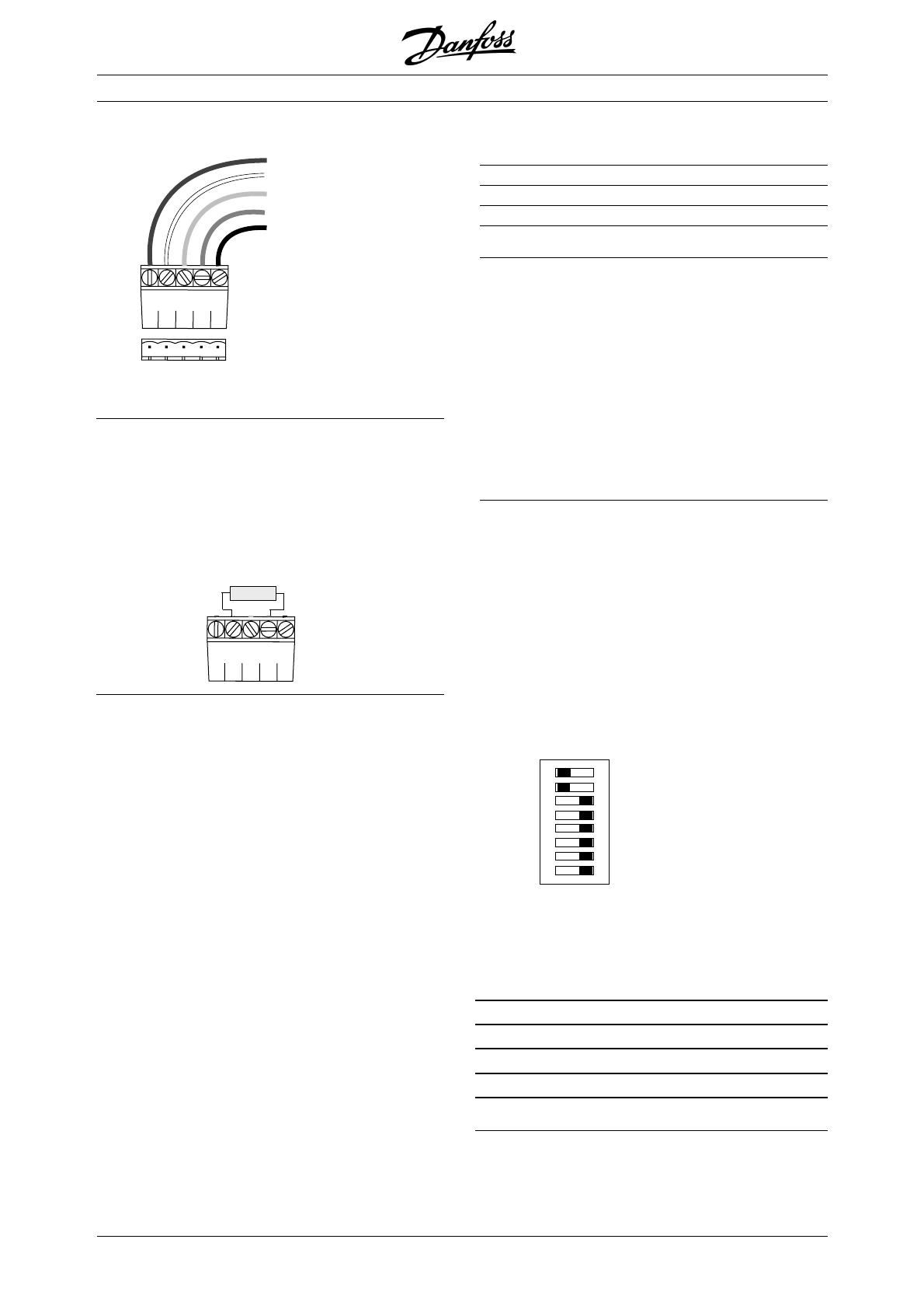
■ DeviceNet connection
■■
■■
■ DeviceNet termination
Termination resistors should be installed at each end
of the bus line.
The resistors must be mounted between terminal 2
CAN_L and terminal 4 CAN_H and should have the
following specification:
5 V+
4 CAN_H
3 drain
2 CAN_L
1 V–
red
white
bare
blue
black
1 2 3 4 5
121 Ohm, 1 % Metal film and 1/4 Watt
■ LEDs
For the device status LED:
1. when the LED is off, the device is off
2. when the LED is green, the device is
operational
3. When the LED is flashing green, the device
is in standby
4. when the LED is flashing red, the device
detects a minor fault
5. when the LED is red, the device detects
an unrecoverable fault
6. when the LED is flashing red/green, the
device is self testing
For the network status LED:
1. when the LED is off, the network is non-
powered/not online
2. when the LED is flashing green, the
network is online but not connected
3. when the LED is green, the network is
online and connected
4. when the LED is flashing red, the network
has a connection time-out
5. when the LED is red, the network has a
critical link failure.
■ Cable length
Transmission speed Max. total cable length [m]
125 kBaud 500
250 kBaud 250
500 kBaud 100
■■
■■
■ Cable specification
- Cross section: max. 0.78 mm
2
,
corresponding to AWG 18
- Cable type: twisted in pairs, 2 x 2 wires with
drain wire in center
- Screening: Copper-braided screen
or braided screen and foil screen
It is recommended to use the same cable type in
the entire network to avoid impedance mismatch.
■■
■■
■ Address and baud rate setting
Dip switch 1-6 set the VLT frequency converters
address and 7-8 the baud rate.
When setting the address/Mac ID you must ensure
that each device on the network has a unique
address. The address/Mac ID can be read in
parameter 918 Mac ID.
Switch 6 is the Most Significant Bit (MSB) and
Switch 1 is the Least Significant Bit (LSB).
If the address is to be set to 3, the dip switches
should be set as follow:
1
2
34
5
6
7
8
ON
ON = 0
OFF = 1
Switch Settings for DeviceNet Module Baud Rate:
Baud Switch Switch
Rate Setting Setting
87
125 kBPS 0 0
250 kBPS 0 1
500 kBPS 1 0
125 kBPS 1 1