Page is loading ...

Universal Modular Plug
Crimping Tool and Cable
Tester Instructions
Model 780124
ATTENTION: Make sure to read and understand these instructions before completing any
of the functions described in this manual. Keep this document for future reference.
WARNING: DO NOT USE THIS TESTER ON LIVE CIRCUITS!
NOTE: This product is equipped with 8-position modular jacks. Users can test cables with
smaller 6- or 4-position connectors, but be advised that repeated jack insertions for the
testing of smaller connectors will reduce the number of credible readings over the
product’s lifetime.
Debug Example
Short Flash
Long Flash
Red LED Fault
Result
1-2 1-2 None Good Pair
1-2 1-2 Reversal Pair reversed 1-2 2-1
1-2 1-2 Short Pin 1 shorted to Pin 2
1-2 1-2, 3-6 Short 1 or 2 shorted to 3 or 6
1-2 7-8 Miswire Pin 1-Pin7, Pin 2-Pin 8
1-2 7-8 Miswire, Reversal Pin1-Pin 8, Pin 2-Pin 7
1-2 1-2 Split Pair
Wire pairs twisted
Important: Read before use. • Importante: Leer antes de usar.
intellinetnetwork.com
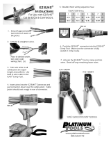
A. Main Unit UTP/STP Cable Jack
B. Remote
C. Wiring Status Indicators
D. Test Button
E. Network Cable Stripper
F. Flat Cable Stripper
G. Cutting Blades
H. RJ45 Crimp Station
I. RJ11/RJ12 Crimp Station
J. RJ22 Crimp Station (Back Side)
B
F
C
DE
G
H
I
J
A
ENGLISH: For warranty information, go to
intellinetnetwork.com/warranty.
DEUTSCH: Garantieinformationen nden Sie hier unter
intellinetnetwork.com/warranty.
ESPAÑOL: Si desea obtener información sobre la garantía, visite
intellinetnetwork.com/warranty.
FRANÇAIS: Pour les informations sur la garantie, visitez
intellinetnetwork.com/warranty.
POLSKI: Informacje dotyczące gwarancji znajdują się na stronie
intellinetnetwork.com/warranty.
ITALIANO: Per informazioni sulla garanzia, accedere a
intellinetnetwork.com/warranty.
EN MÉXICO: Póliza de Garantia Intellinet — Datos del importador y
responsable ante el consumidor — IC Intracom México, S.A.P.I. de C.V.
Av. Interceptor Poniente # 73, Col. Parque Industrial La Joya, Cuautitlán
Izcalli, Estado de México, C.P. 54730, México. • Tel. (55)1500-4500
La presente garantía cubre este producto por 3 años contra cualquier
defecto de fabricación en sus materiales y mano de obra, bajo las
siguientes condiciones: 1) todos los productos a que se reere
esta garantía, ampara su cambio físico, sin ningún cargo para el
consumidor; 2) El comercializador no tiene talleres de servicio, debido
a que los productos que se garantizan no cuentan con reparaciones,
ni refacciones, ya que su garantía es de cambio físico; 3) La garantía
cubre exclusivamente aquellas partes, equipos o sub-ensambles que
hayan sido instaladas de fábrica y no incluye en ningún caso el equipo
adicional o cualesquiera que hayan sido adicionados al mismo por el
usuario o distribuidor.
Para hacer efectiva esta garantía bastará con presentar el producto al
distribuidor en el domicilio donde fue adquirido o en el domicilio de IC
Intracom México, S.A.P.I. de C.V., junto con los accesorios contenidos
en su empaque, acompañado de su póliza debidamente llenada y
sellada por la casa vendedora (indispensable el sello y fecha de compra)
donde lo adquirió, o bien, la factura o ticket de compra original donde
se mencione claramente el modelo, número de serie (cuando aplique)
y fecha de adquisición. Esta garantía no es válida en los siguientes
casos: Si el producto se hubiese utilizado en condiciones distintas a las
normales; si el producto no ha sido operado conforme a los instructivos
de uso; o si el producto ha sido alterado o tratado de ser reparado por el
consumidor o terceras personas.
Warranty Information
INT-780124_QiG-0218_REV-5.02Printed on recycled paper.
© IC Intracom. All rights reserved. Intellinet is a trademark of IC Intracom,
registered in the U.S. and other countries.
All trademarks and trade names are the property of their respective owners.
North & South America
IC Intracom Americas
550 Commerce Blvd.
Oldsmar, FL 34677 USA
Asia & Africa
IC Intracom Asia
4-F, No. 77, Sec. 1, Xintai 5th Rd.
Xizhi Dist., New Taipei City 221, Taiwan
Europe
IC Intracom Europe
Löhbacher Str. 7
D-58553 Halver, Germany
To Test Patch Cables
1 Connect one end of the cable to the main unit (A).
2 Connect the other end of the cable to the remote unit (B).
3 Press the Test button (D) to begin.
4 View the LEDs (C) to read the status of the wire connections.
To Test Installed Cables
1 Using a jumper cable, connect the wall jack or patch panel to the remote unit (B).
2 Using a jumper cable, connect the other wall jack or patch panel to the main unit (A).
3 Press the Test button (D) to begin.
4 View the LEDs (C) to read the status of the wire connections.
Test Results (T568A, T568B, 10Base-T and Token Ring congurations)
PASS Indicators
A green Shield LED indicates that the cable’s shielding is correctly and continuously wired
throughout the plug termination.
Four green LEDs on pairs 1-2, 3-6, 4-5 and 7-8 indicate that all pairs are terminated correctly.
FAIL Indicators
Flashing LEDs over the corresponding wire pairs and in the Fail section indicate where and
what type of fault exists, respectively.
Short indicates that a short-circuit condition has been detected.
Miswire indicates the improper assignment of individual wire pairs to pins for the wiring
schemes tested.
Reversal indicates that one wire in a pair is connected to the opposite pin for the pair in the
remote jack.
Split Pairs indicates when the tip (positive conductor) and ring (negative conductor) of two
twisted pairs are interchanged.
Note: The Crimping Tool and Cable Tester will check fault conditions in descending order
before detecting other fault conditions. The detection and indication of the presence of a
fault is handled on a “one-per-test” basis. Once a fault is corrected, test the cable again for
other faults.
Debug Mode identies which cable pairs have a wiring fault. It cycles through the pairs and
displays test results for one pair at a time. The green and red LEDs work together to reveal
the result. A short green ash on an LED pair is the pair being tested; a long green ash in
the pairs section and a red ash in the fail section species what type of problem exists in
the pair.
1 Press and hold the Test button until all LEDs light; then, release.
2 The pair identication and fail section LEDs light in sequence.
3 If a series of two green LEDs light for a pair, it is wired correctly.
4 A green pair LED then a red LED in the fail section shows the error.
5 The test cycles through the pairs twice before shutting o.
6 To turn the tester o, push and quickly release the Test button.
Battery Installation (batteries not included)
1 Remove battery cover.
2 Insert four LR44 button-cell batteries.
3 Replace cover.
CE
ENGLISH: This device complies with the requirements of CE RED
2014/53/EU, 2014/30/EC and/or 2014/35/EC. The Declaration of
Conformity for is available at:
DEUTSCH: Dieses Gerät enspricht der CE RED 2014/53/EU, 2014/30/EC
und / oder 2014/35/EC. Die Konformitätserklärung für dieses Produkt
nden Sie unter:
ESPAÑOL: Este dispositivo cumple con los requerimientos de CE
RED 2014/53/EU, 2014/30/EC y / o 2014/35/EC. La declaración de
conformidad esta disponible en:
FRANÇAIS: Cet appareil satisfait aux exigences de CE RED 2014/53/
EU, 2014/30/EC et / ou 2014/35/EC. La Déclaration de Conformité est
disponible à:
POLSKI: Urządzenie spełnia wymagania CE RED 2014/53/EU, 2014/30/
EC I / lub 2014/35/EC Deklaracja zgodności dostępna jest na stronie
internetowej producenta:
ITALIANO: Questo dispositivo è conforme alla CE RED 2014/53/
EU, 2014/30/EC e / o 2014/35/EC. La dichiarazione di conformità è
disponibile al:
intellinetnetwork.com
Regulatory Information
Italiano: Attrezzo per crimpatura a spina modulare
universale e tester di cavi
A. Unità principale cavo jack UTP/STP
B. Remoto
C. Indicatori di stato del cablaggio
D. Pulsante di test
E. Spela cavi di rete
F. Spela cavi piatto
G. Lame
H. Stazione crimp RJ45
I. Stazione crimp RJ11/RJ12
J. Stazione crimp RJ22 (lato posteriore)
Per testare i cavi patch
1 Collegare un’estremità del cavo all’unità principale (A).
2 Collegare l’altra estremità del cavo all’unità remota (B).
3 Premere il pulsante Test (D) per iniziare.
4 Visualizzare il LED (C) per leggere lo stato delle connessioni di cavi.
Per testare cavi installati
1 Utilizzando un cavo di collegamento, collegare il jack a muro o il
selezionatore all’unità remota (B).
2 Utilizzando un cavo di collegamento, collegare l’altro jack a muro o il
selezionatore all’unità remota (A).
3 Premere il pulsante Test (D) per iniziare.
4 Visualizzare il LED (C) per leggere lo stato delle connessioni di cavi.
Risultati dei test (T568A, T568B, 10 Base-T e congurazioni Token Ring)
INDICATORI DI SUPERAMENTO DEL TEST
Un LED verde Shield indica che la schermatura dei cavi è correttamente e
costantemente cablata per tutta la terminazione dei cavi.
Quattro LED verdi sulle coppie 1-2, 3-6, 4-5 e 7-8 indica che tutte le coppie
le coppie sono state collegate correttamente.
INDICATORI DI FALLIMENTO
I LED che lampeggiano sulle corrispondenti coppie di cavi e nella sezione
di fallimento indicano rispettivamente dove si trova l’errore e di che tipo è.
Short (Corto) indica che è stato rilevata una condizione di corto circuito.
Miswire (Cavi invertiti)indica l’errata assegnazione di coppie di cavi
individuali alle spine per gli schemi di cablaggio testati.
Reversal (Inversione) indica che un cavo in una coppia è collegato alla spina
opposta per la coppia nel jack remoto.
Split Pairs (Coppie separate) indica quando l’estremità (conduttore positivo)
e l’anello (conduttore negativo) di due coppie attorcigliate si sono scambiati.
Avviso: La crimpatrice e il tester dei cavi controlleranno le condizioni di
errore in ordine decrescente prima di rilevare altre condizioni di errore. Il
rilevamento e l’indicazione della presenza di un errore è gestita in base al
“one-per-test”. Una volta che l’errore è stato corretto, testare nuovamente il
cavo per rilevare nuovi errori.
La modalità Debug identica quali coppie di cavi presentano un difetto
di cablaggio. Compie cicli tra le coppie e mostra i risultati del test per
una coppia alla volta. I LED verdi e rossi funzionano insieme per rilevare il
risultato. Un breve lampeggiamento verde su una coppia LED indica che la
coppia viene testata; un lungo lampeggiamento verde nella sezione delle
coppie e un lampeggiamento rosso nella sezione di fallimento specicano
che tipo di problema esiste nella coppia.
1 Tenere premuto il pulsante Test nché non si illuminano tutti i LED;
quindi, rilasciare.
2 I LED di identicazione delle coppie e sezione di fallimento si illuminano
in sequenza.
3 Se una serie di due LED verdi si illumina per una coppia, quest’ultima è
cablata correttamente.
4 Una coppia di LED verdi e successivamente un LED rosso nella sezione di
fallimento mostrano l’errore.
5 Il test compie due cicli tra le coppie prima di spegnersi.
6 Per spegnere il tester, premere e rilasciare rapidamente il pulsante Test.
Installazione delle batterie (batterie non incluse)
1 Rimuovere il coperchio del vano batterie.
2 Inserire quattro batterie a bottone LR44.
3 Riposizionare il coperchio.
ATTENZIONE: assicurarsi di aver letto e compreso le istruzioni prima di
completare le funzioni descritte in questo manuale. Conservare questo
manuale per poterlo consultare in futuro.
AVVERTENZA: NON UTILIZZARE QUESTO TESTER SU CIRCUITI ATTIVI!
AVVISO: questo prodotto è dotato di jack modulari a 8 posizioni. Gli
utenti possono testare i cavi con connettori a 6 o 4 posizioni più piccoli,
ma si avverte che i ripetuti inserimenti dei jack per i test dei connettori più
piccoli ridurranno il numero di letture credibili nel corso della vita
del prodotto.
Esempio Debug
Breve
Lampeggiamento
Lungo
Lampeggiamento
Guasto rosso
LED
Risultato
1-2 1-2 -- Buona coppia
1-2 1-2 Reversal Coppie Inversione 1-2 2-1
1-2 1-2 Short Pin 1 cortocircuito al Pin 2
1-2 1-2, 3-6 Short 1 o 2 cortocircuito al 3 o 6
1-2 7-8 Miswire Pin 1-Pin7, Pin 2-Pin 8
1-2 7-8 Miswire, Reversal Pin1-Pin 8, Pin 2-Pin 7
1-2 1-2 Split Pair
Coppie contorto
B
F
C
DE
G
H
I
J
A
/