Page is loading ...


DALI-BOX Interface v2
https://www.zennio.com Technical Support: https://support.zennio.com
2
CONTENTS
Document Updates ....................................................................................................................... 4
1 Introduction .......................................................................................................................... 5
1.1 DALI-BOX Interface v2 ................................................................................................... 5
1.2 Installation ..................................................................................................................... 7
1.3 Compatible Ballasts ....................................................................................................... 9
2 Configuration....................................................................................................................... 11
2.1 General Configuration ................................................................................................. 13
2.1.1 Error Objects ....................................................................................................... 18
2.2 Enabling Ballasts .......................................................................................................... 23
2.3 Enabling Groups .......................................................................................................... 25
2.4 Scenes .......................................................................................................................... 26
2.4.1 Configuration ...................................................................................................... 26
2.4.2 Scene N ............................................................................................................... 27
2.5 Sequences ................................................................................................................... 29
2.5.1 Configuration ...................................................................................................... 29
2.5.2 Sequence N ......................................................................................................... 30
2.6 Standby Mode ............................................................................................................. 33
2.7 No Group ..................................................................................................................... 36
2.7.1 ECG n ................................................................................................................... 36
2.8 Group N ....................................................................................................................... 41
2.8.1 Configuration ...................................................................................................... 41
2.8.2 Limits ................................................................................................................... 44
2.8.3 Switch & Dimming .............................................................................................. 45
2.8.4 Status Objects ..................................................................................................... 48
2.8.5 Custom On/Off .................................................................................................... 50
2.8.6 Day/Night Mode ................................................................................................. 51
2.8.7 Timers ................................................................................................................. 52
2.8.8 Lock ..................................................................................................................... 55
2.8.9 Alarm................................................................................................................... 56
2.8.10 Custom Initialisation ........................................................................................... 58

DALI-BOX Interface v2
https://www.zennio.com Technical Support: https://support.zennio.com
3
2.8.11 Modes ................................................................................................................. 59
2.8.12 Colour control ..................................................................................................... 62
2.8.13 ECG M ................................................................................................................. 66
3 Display ................................................................................................................................. 68
3.1 Main Menu .................................................................................................................. 68
3.2 Installation ................................................................................................................... 69
3.2.1 Selection and ECG Testing .................................................................................. 69
3.2.2 Group Assignment .............................................................................................. 70
3.2.3 Address Assignment ........................................................................................... 70
3.2.4 Ballast Errors ....................................................................................................... 71
3.2.5 Operating Time ................................................................................................... 72
3.3 ECG Detection ............................................................................................................. 73
3.4 Switch All ECGs ............................................................................................................ 73
3.5 Reset All ECGs .............................................................................................................. 73
3.6 Manual Control ........................................................................................................... 74
3.7 Scene Control .............................................................................................................. 75
3.8 Burn-in Control ............................................................................................................ 75
3.9 Application Version ..................................................................................................... 76
Annex I. Communication Objects ................................................................................................ 77


DALI-BOX Interface v2
https://www.zennio.com Technical Support: https://support.zennio.com
5
1 INTRODUCTION
1.1 DALI-BOX Interface v2
DALI-BOX Interface v2 from Zennio is a KNX-DALI gateway that allows controlling,
dimming and monitoring up to 64 ballasts in up to 64 groups (16 DALI groups and 48
single groups) in a DALI bus by means of KNX communication objects, which makes it
possible to integrate the DALI installation into the building automation system.
Their main functions are:
General ballast control through universal DALI commands.
Support for up to 64 DALI ballasts in total,
110V or 230V power supply.
Ballast control by groups (16 DALI groups and 48 single groups).
Ballast swap with automatic address re-assignment.
Light regulation with customisable dimming limits and times.
Selection between logarithmic and linear regulation curve.
Support for colour ballasts (DT8 type) compatible with RGB, RBW and colour
temperature functionality.
Support for the Converter modules.
Lock function.
Timed actions: simple timers, flashing sequences and automatic switch-off.
Scenes and sequences.
Custom On/Off controls.
Standby Mode to help save power consumption in the ballasts by controlling
the power supply to the output groups.

DALI-BOX Interface v2
https://www.zennio.com Technical Support: https://support.zennio.com
6
Error detection and notification.
Support for the Burn-in mode, required by certain lamps during the switch-on
in order to ensure an optimal life period.
Test mode and manual configuration of the DALI installation through the
on-board display and pushbuttons.
Heartbeat or periodical “still-alive” notification.

DALI-BOX Interface v2
https://www.zennio.com Technical Support: https://support.zennio.com
7
1.2 INSTALLATION
DALI-BOX Interface v2 connects to the KNX bus through the on-board KNX connector.
Once the device is provided with power from the KNX bus, both the individual address
and the associated application program can be downloaded.
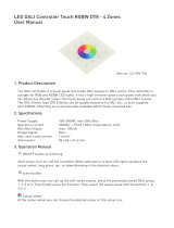
Figure 1. Element Diagram.
The main elements of the device are described next:
Prog./Test button (7): a short press on this button sets the device into the
programming mode, making the associated LED (6) light in red.
Note: if this button is held while plugging the device into the KNX bus, the
device will enter into safe mode. In such case, the LED will blink in red every
0.5 seconds.
DALI bus output (1): slot for the connection of the DALI bus wires.
Neutral and Phase Inputs (5): slots for the connection of the neutral and the
phase of the power line.
Display (2): 128x64-pixel screen that provides information about the device
and the DALI system and allows the execution of different actions.
Control buttons (3): directional arrows (←↑→↓), confirmation button (OK) and
exit button (ESC) that allow browsing through the options on the display.
1. DALI bus output.
2. Display.
3. Control buttons.
4. Power supply indicator LED.
5. External power supply.
6. Prog./Test indicator LED.
7. Prog./Test button.
8. KNX connector.

DALI-BOX Interface v2
https://www.zennio.com Technical Support: https://support.zennio.com
8
To get detailed information about the technical features of the device, as well as on the
installation and security procedures, please refer to the corresponding Datasheet,
bundled with the original package of the device and also available at www.zennio.com.

DALI-BOX Interface v2
https://www.zennio.com Technical Support: https://support.zennio.com
9
1.3 COMPATIBLE BALLASTS
DALI-BOX Interface v2 is able to control DALI-certified ballasts (i.e., with the DALI logo)
that make use of only one individual address. Specifically, it is designed to be compatible
with types 0, 1, 2, 3, 4, 5, 6, 7 and 8 of the DALI device type classification, shown in
Table 1. Please note that future versions of the application program may support
additional ballast types.
Table 1. DALI device type classification.
Proper operation cannot be guaranteed for other ballasts.
Nevertheless, not all DALI-certified ballasts behave the same way – certain particularities
apply:
Ballasts with LED loads do not report lamp failures; therefore, with these
ballasts it is not possible to notify such circumstance to the KNX bus.
When a lamp failure takes place, certain ballasts with fluorescent lamps may
cause the remaining lamps flash briefly.
Fluorescent-lamp ballasts need an extra time to switch off the load when a non-
immediate regulation to 0% is commanded.
Certain ballast models, on the event of a DALI communication error (e.g., short-
circuit or power failure), do not switch to the dimming value configured for such

DALI-BOX Interface v2
https://www.zennio.com Technical Support: https://support.zennio.com
10
circumstance – the ballast will maintain the last dimming value that may have
been set.
Some lamps may implement a significant delay when they are switched on.
Such circumstance must be taken into account in case of parameterising timed
actions or flashing and dimming sequences.
The ability to report ballast errors will depend on the ballast itself. The
documentation provided by the manufacturer should indicate whether such
functionality is available or not.
There may be some other (minor) particularities depending on the ballasts and on the
lamps in the installation. Therefore, the integrator is advised to perform some testing to
ensure compatibility.
Recommendation: it is advisable to install only one ballast type within the same group
in order to avoid ballast control issues.

DALI-BOX Interface v2
https://www.zennio.com Technical Support: https://support.zennio.com
11
2 CONFIGURATION
The DALI-BOX Interface v2 application program allows controlling up to 64 DALI
ballasts divided into up to 64 groups. The groups 1 -16 are defined by the DALI Standard.
The groups 17-64 are not defined by DALI Standard, so it is only possible to set a ballast.
Such control is performed according to a set of customisable options which make DALI-
BOX Interface v2 a very versatile device:
Different alternatives to control the luminosity of the connected loads:
➢ One-bit objects to switch on / switch off each group,
➢ Four-bit objects for per-group step dimming,
➢ One-byte (percentage) objects for absolute dimming (per group).
General dimming features:
➢ Configurable dimming times, being possible to modify them through
communication objects. Up to three different dimming times are available.
➢ Configurable regulation type. Logarithmic and linear regulation are
available.
➢ Dimming limits, i.e., maximum and minimum lighting levels.
➢ Minimum luminosity level reachable by each group, i.e., the ballast
physical minimum.
➢ Maximum luminosity level allowed in the ballasts under the economy
mode.
➢ Standby: mode that allows an external actuator to interrupt the power
supply to the ballasts after switching off the loads, thus reducing the power
consumption.
Custom on/off: possibility of enabling and configuring different switch-on/off
controls for each group, with custom dimming values and times.
Simple timer and flashing: sequence of timed switch-on and switch-off of the
ballasts connected to the device.

DALI-BOX Interface v2
https://www.zennio.com Technical Support: https://support.zennio.com
12
Scenes: up to 64 different customisable scenes, which can be simultaneously
associated to different groups.
Sequences: up to 16 different sequences, which can be associated to different
groups. Up to five step actions per sequence can be defined, as well as the
dimming type of each step action among other things.
Lock: group control enabling/disabling, with the additional option to define
actions for the lock and unlock events.
Initialisation: custom configuration of the initial status (upon the recovery of
the KNX bus power or after an ETS download or a restart) for each group, or
either of an initial sending (immediate or delayed) of the status to the bus.
Error identification: detection of anomalies that may affect the proper
operation of the device: power supply error, short circuit, ballast presence error
or ballast and group diagnostic errors.
Special operation modes:
➢ Auto Off: mode that allows automatically switching off a group in case it
remains steady under a certain parameterisable dimming threshold for
more than a defined time period.
➢ Burn-in: mode that prevents the execution of dimming orders during a
certain, parameterisable time period after the switch-on of the ballast, with
the aim of stabilising the lamp response and of optimising its life time. This
feature may be required by certain lamp models.
ECG Automatic Detection: possibility of enabling the ECG Automatic
Detection.
Collisions Detections: possibility of enabling the Collisions Detections.
Other than these functions, the general settings of the device allow enabling each of the
64 ballasts (or ECGs) supported as maximum and assigning it, if desired, any of the 64
groups available.

DALI-BOX Interface v2
https://www.zennio.com Technical Support: https://support.zennio.com
13
2.1 GENERAL CONFIGURATION
The general configuration of DALI-BOX Interface v2 basically consists in defining the
dimming times. They are the length of the transition from switched off (0%) to the
maximum luminosity level (100%), which determines the speed of the regulation. Up to
three different dimming times can be applied to the different orders or actions, and
their values may be changed through three communication objects (one per each
dimming time).
Note: Due to DALI limitations, every colour dimming has a settled time of 2 seconds from
start value to finish value (except the sequences, see section 2.5).
In case of configuring dimming limits (see section 2.8.2), the dimming times will be
applied as follows:
Transitions between 0% and the minimum dimming value will be
instantaneous.
Transitions between the minimum dimming value and the maximum dimming
value will take the proportional part of the parameterised dimming time (which
must be understood as the time corresponding to the entire transition from 0%
to 100%).
Moreover, the general configuration allows enabling the following functions:
Scenes. See section 2.4.
Sequences. See section 2.5.
Standby. See section 2.6.
Dimming Value During KNX Bus Failure: sets the dimming level that will be
adopted by the ballasts if KNX Bus Failure takes place.
Error Objects. See section 2.1.1.
Heartbeat or periodical “still-alive” notification.
ECG Automatic Detection after download: DALI-BOX Interface v2 is able to
detect new ballast which are just connected to the DALI line, whether or not

DALI-BOX Interface v2
https://www.zennio.com Technical Support: https://support.zennio.com
14
they have an individual address associated, as well as carrying out monitoring
of those ballasts with an individual address detected.
If ECG Automatic Detection is not enabled, DALI-BOX Interface v2 will only be
able to monitor ballast whose individual address have been detected before for
the device.
This functionality can be enabled or disabled by communication object or by
using the display submenu and it can be chosen by parameter if after
downloading it will be enabled by default.
Maintain Previous ECG Detection after Download: DALI-BOX Interface v2
is able to save the configuration and detection of the ballasts after download,
avoiding having to make a new automatic detection of all of them.
If this parameter is disabled, DALI-BOX Interface v2 will not show any ballast
until the automatic detection is done.
Collisions Detections after download: DALI-BOX Interface v2 is able to
analyse the responses of the ballasts to detect those that have been assigned
the same individual address.
This functionality can be enabled or disabled by communication object or by
using the display submenu and it can be chosen by parameter if after
downloading it will be enabled by default.
Important: when Collisions Detection is not enabled, some features as error
detection, ballast configuration, or emergency tests could not work properly.
Notes:
➢ In case the collision detection is disabled and there are several ballasts in
the installation with the same assigned address, all of them will respond in
the same way to the control commands.
➢ To ensure proper operation, it is recommended to enable ECG Automatic
Detection whenever Collisions Detections is activated.
Standard Bit Timing: this function allows customising the time threshold after
which the arrival of a new bit through the DALI bus will be considered as
corrupt, for instance to prevent telegram collisions in case several ballasts have

DALI-BOX Interface v2
https://www.zennio.com Technical Support: https://support.zennio.com
15
been assigned the same address. Preserving the standard threshold is highly
encouraged, unless intending to connect very specific ballasts that may require
modifying it.
Manual Control Lock: provides an optional procedure for locking the manual
control in runtime.
ETS PARAMETERISATION
After importing the corresponding ETS database and adding the device to the project
topology, the configuration process begins by entering the Parameters tab of the device.
The tab tree on the left shows the “General” tab in the first place. This entry itself
comprises the following parameters:
Figure 2. General

DALI-BOX Interface v2
https://www.zennio.com Technical Support: https://support.zennio.com
16
Dimming Times: three dimming times may be parameterised, through the
following parameters:
➢ Dimming Time n [1…5…255] [s/min]
1
: sets dimming time n (1-3).
➢ Dimming Time Objects [enabled/disabled]: enables three general two-
byte objects, named “Dimming Time n”, which allow changing the
dimming times parameterised.
Independent Functions:
➢ Scenes [enabled/disabled]. See section 2.4.
➢ Sequences [enabled/disabled]. See section 2.5.
➢ Standby [enabled/disabled]. See section 2.6.
General Functions:
➢ Dimming Value During KNX Failure [Off / Defined Value / No Change]:
in case of selecting “Defined Value” the ballast will switch to a customisable
value [0…100] [%].
Figure 3. Dimming level for KNX Bus Failure
➢ Error Objects [enabled/disabled]. See section 2.1.1.
➢ Heartbeat (Periodical Alive Notification) [enabled/disabled]: this
parameter lets the integrator incorporate a one-bit object to the project
(“[Heartbeat] Object to Send ‘1’”) that will be sent periodically with a value
of “1” to notify that the device is still working (still alive).
Figure 4. Heartbeat.
1
The default values of each parameter will be highlighted in blue in this document, as follows:
[default/rest of options].

DALI-BOX Interface v2
https://www.zennio.com Technical Support: https://support.zennio.com
17
Note: The first sending after download or bus failure takes place with a delay
of up to 255 seconds, to prevent bus overload. The following sendings
match the period set.
➢ ECG Automatic Detection after Download [enabled/disabled]: enables
or disables the ECG Automatic Detection after download. Regardless of
the value of this parameter, this functionality can be disabled through the
object “ECG Automatic Detection”, which is always available, or through
the display submenu (see section 3.3).
➢ Maintain Previous ECG Detection after Download [enabled/disabled]:
maintain the detection and configuration of the ballasts after download.
➢ Collisions Detection after Download [enabled/disabled]: enables or
disables the Collisions Detection after download. Regardless of the value
of this parameter, this function can be activated or deactivated with the
“Collisions Detection” object, which is always available.
➢ Standard bit timing [enabled/disabled]: allows enabling or disabling the
manual configuration of the bit detection time. The standard value set by
default is 500 μs.
• Maximum time for one-bit phase [500…650]: sets the new
threshold value.
Note: preserving the standard threshold is highly encouraged, unless
intending to connect very specific ballasts that may require modifying it.
Figure 5. Standard Bit Timing.
➢ Manual Control Lock Object [enabled/disabled]: when enabled, 1-bit
object “Manual Control Lock Object” turns visible, as well as two more
parameters:
• Object Polarity [0 = Unlock; 1= Lock / 0 = Lock; 1 = Unlock]: defines
whether the manual control lock/unlock should take place respectively

DALI-BOX Interface v2
https://www.zennio.com Technical Support: https://support.zennio.com
18
upon the reception (through the aforementioned object) of values “0”
and “1”, or the opposite.
• Initialization [Unlock / Locked / Last Value]: sets how the manual
control should remain after the device start-up (after an ETS download
or a bus power failure). On the very first start-up, “Last Value” will be
Unlocked).
Figure 6. Manual Control Lock Object
2.1.1 ERROR OBJECTS
DALI-BOX Interface v2 is able to detect certain errors that may occur during normal
operation, which will be indicated through the display (section 3) or reported to the KNX
bus (periodically every minute), if configured.
The DALI power supply error is reported when the external power supply is
interrupted and therefore the DALI bus becomes non-functional. In such case,
the ballasts will adopt the level configured for DALI bus failure cases (see
section 2.8.1), as the ballasts have their own power supply. In case this is
interrupted too, they will obviously switch off.
During the power supply error, control actions will be ignored. Other error
types will not be reported, either. Nevertheless, the lock objects (see section
2.8.8) will be taken into account so once the error is over the corresponding
action can be performed.
The short-circuit error is reported in case the communication is interrupted
due to issues on the DALI bus. In such cases, the ballasts will acquire the value
configured for DALI bus failure cases (see section 2.8.1).
While this error persists, the following errors will no longer be notified,
due to a lack of communication with the ballasts:
➢ ECG presence error (see below).

DALI-BOX Interface v2
https://www.zennio.com Technical Support: https://support.zennio.com
19
➢ ECG and group diagnostic (see below).
The ECG presence error is notified when at least one of the already-detected
ballasts no longer responds. The detection of this error may not be immediate,
being it possible that the device takes up to two minutes to report it. If a
regulation order is sent to a ballast whose presence error has not been
detected yet, the order will not be executed and one of the following will take
place:
➢ If the error is solved before having been detected, the ballast will remain
under a wrong dimming value until the next regulation order.
➢ If the error is finally detected, once it is solved the ballast will be regulated
to the last value received from the KNX bus.
Important:
➢ To let reducing the number of ballasts in the installation (which may
cause a permanent ballast presence error), the Write flag of the
communication object that reports this error has been enabled, so the
error can be cleared by sending it the value “0”. Whenever this happens,
the device will assume the current number of ballasts as correct. This can
also be done via the display, as detailed in section 3.
➢ To replace a defective ballast, please proceed as follows:
1. Disconnect the defective ballast keeping DALI-BOX Interface on.
2. Wait for the detection of the ECG presence error (which may take
up to 120 seconds).
3. Clear the ballast presence error (via object or display).
4. Connect the new ballast (it will be assigned the first DALI address
available).
5. Assign the new ballast the address of the removed ballast.
If, despite following these steps, the new ballast is not detected correctly
or is not well configured, disconnect it for at least two minutes and
reconnect it. Thus, DALI-BOX Interface will reconfigure it.

DALI-BOX Interface v2
https://www.zennio.com Technical Support: https://support.zennio.com
20
Note: in case an open circuit takes place (either due to the disconnection of
the DALI bus or to a general power failure of the ballasts), DALI-BOX Interface
v2 will report an ECG presence error for each ballast.
The diagnostic errors are errors detected by the ballasts themselves. DALI-
BOX Interface v2 is informed about them when it requests the status from the
ballast.
➢ ECG Failure: the ballast cannot operate normally. The reasons that cause
this error depend on the manufacturer.
➢ Lamp failure: the lamp cannot be switched on normally, either due to a
defect (burned-out bulb) or to an incorrect connection.
Note: the dimming level must be higher than 0% in order to detect the lamp
failure error. Otherwise, even if the lamp is burnt out, the ECG will not be
able to detect it.
Note that in case the ballast does not implement this function, DALI-BOX
Interface v2 will not be able to report these errors (see section 0).
Blocking errors (short-circuit and lack of power supply) will interrupt all actions,
including timed actions. Other errors will not interrupt them – they will still be executed
by all connected ballasts that do not present errors.
ETS PARAMETERISATION
The Error Objects function can be parameterised from the “General” tab. Once enabled
through its own checkbox, the following options become available:
Figure 7. Error Objects
/