Page is loading ...

Quick Start Guide, 61200825G1-13A, February 2011 1
NETVANTA OCTAL POE UPGRADE
P/N 4200825G1#120, 4200825G1#240
4 Copyright © 2011 ADTRAN, Inc. All Rights Reserved.
GETTING STARTED
The NetVanta Power over Ethernet (PoE) Upgrade provides the ability to detect attached
powered devices (PDs) and deliver 48 VDC to the PDs via existing CAT 5 cabling. The NetVanta
PoE Upgrade bundle is shipped with the Octal PoE module, two standoffs, the PoE power supply,
and appropriate power cords.
INSTALLING THE OCTAL POE MODULE
1. Remove power and all connecting cables from the unit.
2. Remove any installed network interface modules (NIMs), the screws holding the base unit
and the cover together, the two jack screws from the back panel (if necessary), and the two
mounting brackets (if necessary).
3. Carefully lift and remove the unit’s cover to expose the main circuit board.
4. Remove and retain the two PC board mounting screws (highlighted in Figure 1).
5. Thread and secure the two standoffs (supplied with the Octal PoE module) into the two
holes from which you removed the PC board mounting screws (see Figure 1).
6. Carefully align the 34-pin receptacle on the Octal PoE module with the 34-pin header
located on the circuit board. Applying even pressure, press the module until it is well seated.
7. Align the holes in the standoffs with the holes in the Octal PoE module. Attach the module to
the standoffs using the two previously removed PC board mounting screws.
8. Replace the unit cover, screws, mounting brackets, NIMs, and all connecting cables.
9. If wall mounting the power supply, skip to steps given in Wall Mounting the PoE Power
Supply (Optional).
10. Restore power to the unit following the instructions in Powering the NetVanta and PoE
Switchports.
Installation of the NetVanta Octal PoE module is not required on factory-
installed upgrades.
The NetVanta Octal PoE module is intended to be installed only by
qualified service personnel.
POWERING THE NETVANTA AND POE SWITCHPORTS
1. Plug the 2-pin connector from the PoE power supply into the PoE receptacle on the rear
panel of the NetVanta base unit.
2. Plug the female end of the power supply’s power cord into the AC Input receptacle on the
power supply.
3. Connect the other end (3-prong plug) of the PoE power supply’s power cord to the proper
100 to 130 VAC or 190 to 250 VAC receptacle.
4. Plug the NetVanta base unit‘s power cord into the AC Input receptacle on the rear of the
unit.
5. Connect the other end (3-prong plug) of the NetVanta base unit’s power cord to the proper
100 to 130 VAC or 190 to 250 VAC receptacle.
The NetVanta PoE power supply and the NetVanta base unit with
which it is associated both should be installed in a restricted
access location as described in UL 60950-1.
Under full load, the NetVanta PoE power supply may be hot to the
touch.
The NetVanta PoE power supply is intended
• to be installed, maintained, and serviced by qualified service
personnel only.
• for use only with NetVanta units with the Octal PoE Upgrade
module installed.
• This unit shall be installed in accordance with Articles 300 and 400
of NEC NFPA 70.
• Power to the AC system must be from an appropriately rated and
grounded source.
• Maximum recommended ambient operating temperature is 50
o
C.

2 Copyright © 2011 ADTRAN, Inc. All Rights Reserved. Quick Start Guide, 61200825G1-13A, February 2011 3
Figure 1. Installing the PoE Module
Before touching electronic components, make sure you are properly
grounded. By wearing a wrist strap (or using some other type of static
control device), you can prevent static electricity stored on your body or
clothing from damaging your installation.
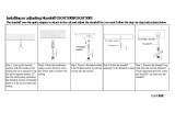
WALL MOUNTING THE POE POWER SUPPLY (OPTIONAL)
1. Decide on a location for the power supply. Keep in mind that the power supply needs to be
mounted close enough to the NetVanta unit for the cords to reach the receptacles.
2. Prepare the mounting surface by attaching a board (typically plywood, 3/4-inch to 1-inch
thick) to a wall stud (see Figure 2).
Important! Mounting to a stud ensures stability. Using sheetrock anchors may not
provide sufficient long-term stability.
3. Install two #8 PAN head screws (1-inch or greater in length) wood screws into the mounted
board, following these guidelines:
• Mark the exact positioning of the screws by using the keyhole slots on the sides of the
unit as a template.
• Screws should be horizontally level with each other.
• Leave approximately 1/4-inch of the screws protruding from the board to allow the heads
of the screws to slide into place in the unit’s keyhole slots.
4. Insert the screws through the keyhole slots in both sides of the unit and slide the slot
securely onto the screws.
5. Proceed to the steps given in Powering the NetVanta and PoE Switchports.
Figure 2. Wall Mounting the Power Supply

2 Copyright © 2011 ADTRAN, Inc. All Rights Reserved. Quick Start Guide, 61200825G1-13A, February 2011 3
Figure 1. Installing the PoE Module
Before touching electronic components, make sure you are properly
grounded. By wearing a wrist strap (or using some other type of static
control device), you can prevent static electricity stored on your body or
clothing from damaging your installation.
WALL MOUNTING THE POE POWER SUPPLY (OPTIONAL)
1. Decide on a location for the power supply. Keep in mind that the power supply needs to be
mounted close enough to the NetVanta unit for the cords to reach the receptacles.
2. Prepare the mounting surface by attaching a board (typically plywood, 3/4-inch to 1-inch
thick) to a wall stud (see Figure 2).
Important! Mounting to a stud ensures stability. Using sheetrock anchors may not
provide sufficient long-term stability.
3. Install two #8 PAN head screws (1-inch or greater in length) wood screws into the mounted
board, following these guidelines:
• Mark the exact positioning of the screws by using the keyhole slots on the sides of the
unit as a template.
• Screws should be horizontally level with each other.
• Leave approximately 1/4-inch of the screws protruding from the board to allow the heads
of the screws to slide into place in the unit’s keyhole slots.
4. Insert the screws through the keyhole slots in both sides of the unit and slide the slot
securely onto the screws.
5. Proceed to the steps given in Powering the NetVanta and PoE Switchports.
Figure 2. Wall Mounting the Power Supply

Quick Start Guide, 61200825G1-13A, February 2011 1
NETVANTA OCTAL POE UPGRADE
P/N 4200825G1#120, 4200825G1#240
4 Copyright © 2011 ADTRAN, Inc. All Rights Reserved.
GETTING STARTED
The NetVanta Power over Ethernet (PoE) Upgrade provides the ability to detect attached
powered devices (PDs) and deliver 48 VDC to the PDs via existing CAT 5 cabling. The NetVanta
PoE Upgrade bundle is shipped with the Octal PoE module, two standoffs, the PoE power supply,
and appropriate power cords.
INSTALLING THE OCTAL POE MODULE
1. Remove power and all connecting cables from the unit.
2. Remove any installed network interface modules (NIMs), the screws holding the base unit
and the cover together, the two jack screws from the back panel (if necessary), and the two
mounting brackets (if necessary).
3. Carefully lift and remove the unit’s cover to expose the main circuit board.
4. Remove and retain the two PC board mounting screws (highlighted in Figure 1).
5. Thread and secure the two standoffs (supplied with the Octal PoE module) into the two
holes from which you removed the PC board mounting screws (see Figure 1).
6. Carefully align the 34-pin receptacle on the Octal PoE module with the 34-pin header
located on the circuit board. Applying even pressure, press the module until it is well seated.
7. Align the holes in the standoffs with the holes in the Octal PoE module. Attach the module to
the standoffs using the two previously removed PC board mounting screws.
8. Replace the unit cover, screws, mounting brackets, NIMs, and all connecting cables.
9. If wall mounting the power supply, skip to steps given in Wall Mounting the PoE Power
Supply (Optional).
10. Restore power to the unit following the instructions in Powering the NetVanta and PoE
Switchports.
Installation of the NetVanta Octal PoE module is not required on factory-
installed upgrades.
The NetVanta Octal PoE module is intended to be installed only by
qualified service personnel.
POWERING THE NETVANTA AND POE SWITCHPORTS
1. Plug the 2-pin connector from the PoE power supply into the PoE receptacle on the rear
panel of the NetVanta base unit.
2. Plug the female end of the power supply’s power cord into the AC Input receptacle on the
power supply.
3. Connect the other end (3-prong plug) of the PoE power supply’s power cord to the proper
100 to 130 VAC or 190 to 250 VAC receptacle.
4. Plug the NetVanta base unit‘s power cord into the AC Input receptacle on the rear of the
unit.
5. Connect the other end (3-prong plug) of the NetVanta base unit’s power cord to the proper
100 to 130 VAC or 190 to 250 VAC receptacle.
The NetVanta PoE power supply and the NetVanta base unit with
which it is associated both should be installed in a restricted
access location as described in UL 60950-1.
Under full load, the NetVanta PoE power supply may be hot to the
touch.
The NetVanta PoE power supply is intended
• to be installed, maintained, and serviced by qualified service
personnel only.
• for use only with NetVanta units with the Octal PoE Upgrade
module installed.
• This unit shall be installed in accordance with Articles 300 and 400
of NEC NFPA 70.
• Power to the AC system must be from an appropriately rated and
grounded source.
• Maximum recommended ambient operating temperature is 50
o
C.
/