Tyco NG-1 100 / NG-1 250 / NG-1 500 Installation guide
- Category
- Fire protection
- Type
- Installation guide

NG-1 100 / 250 / 500
Wall-Mounted Nitrogen Generator System
Installation Manual
TFP1273
APRIL 2021

TFP1273 Page 1 of 80
Table of Contents
1. General ..……………………………………………………………………………………………………………….. 2
a. Safety
b. System and Product Information
c. Technical Specifications
d. Operational Information
2. Start-Up and Operational Procedures………………....………………………………………………… 13
a. Installation
b. Start-Up Procedure
c. Normal Operation
d. Fire Sprinkler System Maintenance Procedure
3. Sequence of Operation …………………………………………………………………………………………. 22
4. Auxiliary Equipment ..……………………………………………………………………………………………. 26
a. Oxygen-Removal Vent – TYCO TAV-D Vent
b. Oxygen-Removal Vent – TYCO TSV-D SMART Vent
c. Monitoring – Corrosion Detection
d. Monitoring – Nitrogen Purity Level
5. Commissioning………………………………………………………………………………………………………. 42
a. Commissioning Procedure
b. Commissioning Checklist
6. Maintenance………………………………………………………………………………………………………….. 53
a. Safety, Maintenance, Troubleshooting Warnings
b. Routine Checks
c. Nitrogen Purity and Flow Rate
d. Filter Replacement
e. Vent Maintenance
f. Generator Configuration Diagrams
g. Troubleshooting
h. Wiring Diagrams
7. Appendix ……………………………………………………………………………………………………..……….. 78
a. System Summary
b. Inspection, Testing, and Maintenance Report

TFP1273 Page 2 of 80
General
SAFETY
Safety Guidelines
The manual contains safety information that is important to know and understand. The information is
provided for the safety of the installers, operators and users of the TYCO Nitrogen Generation Systems,
as well as the nitrogen generation equipment.
The Installation and Operations Manual that is supplied with each nitrogen generation system must be
read thoroughly and be completely understood prior to installing and operating the TYCO Nitrogen
Generation System. All appropriate safety standards for the handling of gases as determined by local,
state or national laws and regulations are to be followed at all times.
General Safety Information
IMPORTANT: Read all the safety information in the manual prior to operating the equipment. Use of the
equipment in a manner not specified within the manual could impair the protection
provided by the nitrogen generation system and could result in an unintended release of
pressure which could cause serious injury or damage. Only qualified personnel can perform
commissioning, servicing and repair procedures.
When handling, installing, or operating the nitrogen generation equipment, the personnel must employ
safe engineering practices and observe all related local, state and national regulations, health, and safety
procedures, and legal requirements for safety.
Ensure the nitrogen generation equipment is depressurized and electrically isolated, before performing
any maintenance or troubleshooting instructions specified in this manual.
The warnings covered in this manual are the most known potential hazards, but by definition cannot be
all-inclusive. If the user employs an operating procedure, item of equipment, or method of working that
is not specifically recommended by Johnson Controls, the user must ensure that the equipment will not
be damaged or become hazardous to any persons or property.
Cautions and Warnings
CAUTION: Do not install the TYCO Nitrogen Generator or Air Compressor Package in an area where
ammonia, sulfur dioxide, hydrogen sulfide, mercaptans, chlorides, chlorine, oxides of
nitrogen, acid fumes, solvent vent vapors, and ozone vapors or similar contaminates exist.
The equipment can be damaged by ammonia and other vapors shortening membrane life.
WARNING: Do not operate the TYCO Nitrogen Generation System if damaged during shipment, handling
or use. Damage could result in injury or property damage.

TFP1273 Page 3 of 80
WARNING: Operation of the nitrogen membrane above the rated design pressure could be hazardous.
Do not connect the nitrogen generation equipment to compressed air sources that can exceed
the maximum rated pressure without installing pressure controls and safety relief devices in
the compressed air supply line
Specific procedures must be developed for maintenance and servicing of the equipment
where the nitrogen membrane is located. Appropriate labels must be continuously displayed
in all areas where personnel might be exposed to a nitrogen atmosphere under normal and
abnormal conditions.
WARNING: Nitrogen is nontoxic and largely inert. Rapid release of nitrogen gas into an enclosed space
displaces the oxygen and can cause an asphyxiation hazard.
Maintenance and Troubleshooting Warnings
1. Nitrogen Generator includes 120-240 VAC 50/60 Hz voltage inside cabinet – exercise caution and
do not touch any wiring connections when power is applied to the unit.
2. Nitrogen Generator has hot surfaces inside cabinet when nitrogen generator is operating and
after nitrogen generator has turned off – exercise caution when working on nitrogen generator
while operating and after nitrogen generator has shut off. (Wear Hand Protection, where needed)
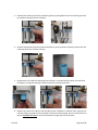
Lifting and Troubleshooting Instructions
Nitrogen Generators weigh in excess of 100 lbs (45 kg). When lifting and/or carrying a nitrogen generator,
proper lifting and carrying techniques must be considered.
1. Keep a wide base of support – Feet should be shoulder-width apart with one knee slightly in front
of the other.
2. Squat down bending at hips and knees – If needed, one knee on the floor and other knee in front,
bent at a right angle.
3. Keep good posture - Look straight ahead with back straight, chest out, and shoulders back.
4. Slowly lift by straightening your hips and knees (not your back) - Keep your back straight, and
don't twist as you lift.
5. Hold the load as close to body as possible.
6. Use feet to change direction - Small steps.
7. Lead with hips as changing direction - Keep shoulders in line with hips as you move.
8. Set down load carefully - Squatting with the knees and hips only.

TFP1273 Page 4 of 80
SYSTEM and PRODUCT INFORMATION
Dry Pipe Nitrogen Inerting (DPNI)
Dry Pipe Nitrogen Inerting technology is used to control oxygen corrosion in dry pipe and/or preaction fire
sprinkler systems. DPNI is executed by employing a “fill and purge” differential pressure cycle (breathing)
within the sprinkler pipe network. The “fill and purge” pressure cycle consists of venting the system
pressure by 3-5 psi (.2-.3 bar), followed by replacing the vented pressure back into the system. This
breathing process uses a nitrogen rich gas stream, typically 98% or greater, for a specific length of time
(typically 14 days or less), until a nitrogen-rich, or inert, atmosphere exists within the sprinkler pipe
network. By changing the atmosphere inside the pipe network to 98% or higher nitrogen content, the
available oxygen content is reduced to a level that will not allow appreciable corrosion of the fire sprinkler
pipe. With the level of oxygen corrosion reduced to near zero the effective life of the fire sprinkler system
is greatly extended. Systems that implement a DPNI corrosion control strategy should never develop leaks
when maintained properly.
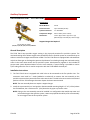
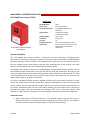
Dry Pipe Nitrogen Inerting Equipment
Pre-Engineered Nitrogen Generator
The TYCO Pre-Engineered Nitrogen Generator is a wall mounted, “plug and play” on-site nitrogen
generation system that is designed to be installed in-line to the fire sprinkler system riser(s) in dry pipe
and preaction fire sprinkler systems. The TYCO Pre-Engineered Nitrogen Generator includes an oil-less
compressor within the nitrogen generator cabinet. The cabinet includes a 3-way ball valve and outlet
connection to the fire sprinkler system(s). The 3-way valve allows for the air compressor in the nitrogen
generator to be used for maintenance or sprinkler system “fast fill” needs. The TYCO Pre-Engineered
Nitrogen Generator has been sized with an air compressor to meet the NFPA 13 30-minute fill requirement
for dry pipe fire sprinkler systems based on the criteria defined in the Technical Specifications Section. In
applications outside of the defined criteria, a separate air compressor can be used to meet the NFPA 13
30-minute fill requirement. The TYCO Pre-Engineered Nitrogen Generator facilitates “fill and purge”
breathing in the fire sprinkler system and has been paired with a TYCO Manual Vent (TAV-D) or a TYCO
SMART Vent (TSV-D) installed on the fire sprinkler riser.
Nitrogen Generator Features
The TYCO nitrogen generators with the “fill and purge” breathing technology include the following
features:
• Removal of corrosive oxygen from the entire sprinkler system in fourteen (14) days or less
• All equipment is installed in the sprinkler riser room for easier installation and servicing
• No refrigerated dryers or nitrogen storage tanks required
• Nitrogen generation system monitoring
• Membrane separation technology with 20-year service life
• Minimal maintenance requirements

TFP1273 Page 5 of 80
Oxygen Removal Vent
To completely remove the oxygen in a dry pipe or preaction fire sprinkler system, it is necessary to install
a vent on the main riser of each fire sprinkler system. Vents allow for a system to breathe, which requires
a 3-5 psig (.2-.3 bar) pressure range to facilitate removal of oxygen gas from the system. Supervisory
nitrogen gas is supplied to the system until the air maintenance device reaches the high-end pressure.
The vent slowly releases the gas mixture inside the sprinkler system through the restricted orifice until
the system reaches the low-end pressure at which point supervisory nitrogen is supplied to the system
again. This process is repeated numerous times until the atmosphere inside the piping network reaches
at least 98% nitrogen. The vent is crucial for expedient mixing of the gas and elimination of oxygen inside
the system within the specified timeframe. TYCO offers two (2) DPNI vents – the TSV-D SMART Vent and
the TAV-D Vent. The TSV-D SMART Vent is an automated vent that when activated will open and vent for
the necessary amount of time to achieve the desired inert inner pipe atmosphere, and close automatically
when the process is completed. This process is initiated by depressing the “vent” pushbutton on the vent’s
control panel. The TAV-D is a manual vent that requires an operator to open the vent’s isolation ball valve
when venting is desired, and after a specified time (typically 14 days or less) when the breathing process
is completed the operator must manually close the isolation ball valve on the vent.
Oxygen Removal Vent Features
The TYCO oxygen removal vents with the “fill and purge” breathing technology include the following
features:
• Removal of corrosive oxygen from the entire sprinkler system in fourteen (14) days or less
• All equipment is installed in the sprinkler riser room for easier installation and servicing
• No support hanger required
• Backpressure regulator preventing system depressurization from vent
• In-line filter to protect restricted venting orifice from contamination
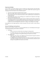
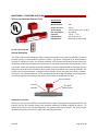
Recommended Monitoring Equipment
In-Line Corrosion Detectors
The TYCO In-Line Corrosion Detector (TILD) is designed to provide an early warning of corrosion activity
within the fire sprinkler system. The TILD features a double wall construction that incorporates a thin
milled section of pipe (.035” (0.9mm)) surrounded by a full thickness piece of pipe to detect and alert to
the presence of corrosion activity. If corrosion occurs the milled section of the TILD will fail prior to the
failure of any other section of the pipe wall. When the milled section fails it allows the system to pressurize
the chamber outside the milled section of pipe which activates the attached pressure switch on the TILD.
The pressure switch can be remotely monitored through a building monitoring system, or locally through
the TYCO Remote Test Station (TRTI) which is included with the TILD.

TFP1273 Page 6 of 80
The TILD is placed at strategic locations within the fire sprinkler piping network where corrosion has the
highest potential of occurring.
• Wet Systems - The TILD is located in high point of the sprinkler system, typically at the air/water
interface in a branch line, where air will be trapped as the system is filled with water.
• Dry Systems - The TILD is located in a horizontal portion of the supply main piping where trapped
water will accumulate.
SMART Gas Analyzer
The TYCO SMART Gas Analyzer provides continuous real-time nitrogen/oxygen concentration levels within
a dry pipe or preaction fire sprinkler system. The analyzer samples discharge gas from an adjacent TYCO
TAV-D Vent or TSV-D SMART Vent. It is equipped with programmable outputs for one of three different
oxygen concentration levels (1%, 3%, and 5%), providing early warning to a user when the nitrogen
concentration within the fire sprinkler system falls below the desired level. The TSGA is also equipped
with an RS-485 port for optional remote control and monitoring and can also display either oxygen or
nitrogen concentration.
Handheld Gas Analyzer
The TYCO handheld gas analyzer allows for quick, convenient reading of nitrogen gas purity levels. The
gas analyzer can be connected to any of the sample ports on the TYCO devices such as the nitrogen
generator or a vent. Additional sampling ports can be ordered and placed at any point on the systems
where gas purity monitoring is desired.

TFP1273 Page 7 of 80
TECHNICAL SPECIFICATIONS
Nitrogen Generators
NG-1 100
Dimensions
24.5" (622mm) W x 36.5" (927mm) H x 9.25" (235mm) D
Weight
125 lbs (57kg)
Air Compressor Output
2.5 SCFM/150 SCFH (70.8 L/min)
Nitrogen Gas Output
0.3 SCFM/20 SCFH (8.5 L/min)
Largest Single Zone Capacity @ 40 psig (2.8 bar)
215 gallons (814 Liters)
Largest Single Zone Capacity @ 20 psig (1.4 bar)
540 gallons (2,044 Liters)
Largest Accumulative System Capacity
675 gallons (2,555 Liters)
NG-1 250
Dimensions
24.5" (622mm) W x 36.5" (927mm) H x 9.25" (235mm) D
Weight
125 lbs (57kg)
Air Compressor Output
3.3 SCFM/198 SCFH (93.5 L/min)
Nitrogen Gas Output
0.45 SCFM/27 SCFH (12.7 L/min)
Largest Single Zone Capacity @ 40 psig (2.8 bar)
265 gallons (1,003 Liters)
Largest Single Zone Capacity @ 20 psig (1.4 bar
590 gallons (2,233 Liters)
Largest Accumulative System Capacity
950 gallons (3,596 Liters)
NG-1 500
Dimensions
28.5" (724mm) W x 36.5" (927mm) H x 11.5" (292mm) D
Weight
175 lbs (79kg)
Air Compressor Output
5.7 SCFM/342 SCFH (161.4 L/min)
Nitrogen Gas Output
.66 SCFM/40 SCFH (18.9 L/min)
Largest Single Zone Capacity @ 40 psig (2.8 bar)
560 gallons (2,120 Liters)
Largest Single Zone Capacity @ 20 psig (1.4 bar)
1,120 gallons (4,240 Liters)
Largest Accumulative System Capacity
2,000 gallons (7,571 Liters)
Technical Specifications – All Generators
Location
Dry Indoor Use
Altitude
Up to 6,560 ft (2,000m)
Temperature Range
40°F - 105°F (5°C - 40°C)
Pollution Degree
2
Nitrogen Generator Cabinet Power Supply
120VAC/1ph/60Hz (230VAC/1 ph/50Hz)
Power Consumption
NG-1 100/250: 6 Amps; NG-1 500: 14.5 Amps
Overvoltage Category
II
Air Inlet Connection
½" NPT Female
Drain Connection
¼" NPT Female
Filter Replacement Part #
TNGFLTW

TFP1273 Page 8 of 80
Nitrogen Quality
N
2
Purity at Discharge: 98% (maximum of 2.0% oxygen)
N
2
Pressure at Discharge: Min: 15 psig (1 bar); Max: feed air pressure minus 15 psig (1 bar)
N
2
Water Dew Point: Less than -70°F (-57°C)
FM Approved Standard 1035
UL Listed 508A Industrial Control Panel
CE Certification

TFP1273 Page 9 of 80
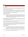
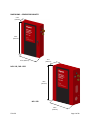
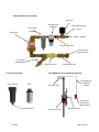
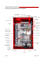
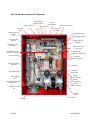
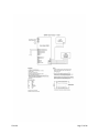
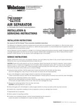
DIMENSIONS – GENERATOR CABINETS
NG-1 100 / NG-1 250
NG-1 500
9.25”
(235mm)
36.5”
(927mm)
24.5” (622mm)
36.5”
(927mm)
28.5”
(724mm)
11.5”
(292mm)

TFP1273 Page 10 of 80
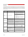
OPERATIONAL INFORMATION
System Operating Pressures
When multiple dry-pipe and/or preaction fire sprinkler systems are connected to one nitrogen generator,
the fire sprinkler systems must operate at the same supervisory gas pressure.
In applications where multiple dry pipe or preaction fire sprinkler systems are connected to one nitrogen
generator and there is more than one supervisory gas pressure a TYCO Nitrogen Interface Controller
(TNIC) must be included in the project.
System Operating Pressure Adjustments
The nitrogen generator operating pressure settings in conjunction with the pressure setting of the fire
sprinkler system’s air maintenance device(s) are established and set during the installation process.
• The operating pressure settings of the fire sprinkler air maintenance device(s) or the nitrogen
generator must not be readjusted after the system has been commissioned.
• Any adjustments to the operating pressure settings of the fire sprinkler air maintenance device(s)
or the nitrogen generator will have an adverse effect on the nitrogen inerting process and could
damage the nitrogen generation equipment.
• Any changes to the fire sprinkler air maintenance device(s) or nitrogen generator operating
pressure settings must be authorized by Johnson Controls.
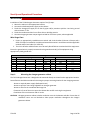
Sprinkler System Gauge Accuracy
The accuracy of the gauges used in fire sprinkler systems can affect the operating pressure of the fire
sprinkler system as well as determining the required 3-5 psig (.2-.3 bar) pressure range needed to properly
remove the oxygen from a fire sprinkler system. NFPA 25 indicates that gauges in excess of ±3% must be
replaced or recalibrated. FM Global allows the gauges used in fire sprinkler systems to be accurate within
±2% over the center third of its scale and ±3% over the remaining two-thirds of its scale. This can become
paramount when operating a low-pressure valve sprinkler system with an operating pressure of 15-20
psig (1-1.4 bar).
Example: NFPA 25 – A 200 psi (14 bar) gauge with ±3% accuracy equates to ±6 psi (.4 bar) variance in the
actual pressure reading of the gauge. Therefore, a sprinkler system indicating a 40 psig (2.8 bar)
operating pressure can actually be operating between 34 psig (2.3 bar) and 46 psig (3.2 bar).
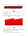
FM Global - A 200 psi (14 bar) gauge with ±2% accuracy in the center third of the gauge equates
to ±4 psi (.3 bar) variance in the actual pressure reading of the gauge; and ±3% accuracy in the
upper and lower third of the gauge equates to ±6 psi (.4 bar) variance in the actual pressure
reading of the gauge.
• A 200 psi (14 bar) gauge on a sprinkler system indicating a 100 psig (6.9 bar) (center
third of the gauge) operating pressure can actually be operating between 96 psig (6.6
bar) and 104 psig (7.2 bar).
• A 200 psi (14 bar) gauge on a sprinkler system indicating a 20 psig (1.4 bar) (lower third
of the gauge) operating pressure can actually be operating between 14 psig (.9 bar) and
26 psig (1.8 bar).

TFP1273 Page 11 of 80
A sprinkler system using a low-pressure valve with a 200 psi (14 bar) gauge indicating a 15 psig (1 bar)
operating pressure can actually be operating between 9 psig (.6 bar) and 21 psig (1.4 bar); which could be
close to the low-air alarm/trip pressure of the sprinkler system.
The digital controller in the TYCO Nitrogen Generator used to turn-on and turn-off the nitrogen generator
is accurate to < ±1.5%.
To ensure proper operation of the sprinkler system and the nitrogen generator, calibrate the sprinkler
system operating pressure to the turn-on pressure of the nitrogen generator using the Air Maintenance
Device (AMD) Pressure Adjustment Procedure in the Maintenance Section of this manual.
The procedure aligns the sprinkler system operating pressure to the turn-on pressure of the nitrogen
generator; reducing the potential of the nitrogen generator turn-on pressure to be set near the low-air
alarm/trip pressure of the sprinkler system.
Sprinkler System Air Maintenance Device
Dry pipe and preaction fire sprinkler systems are to be configured to use a single air maintenance device
(AMD) for each dry pipe and preaction fire sprinkler system in accordance with NFPA 13.
• Applications where multiple fire sprinkler systems are served with a single AMD has been known
to cause nitrogen generators to short cycle due to the air restriction that the AMD imposes on the
nitrogen supply line. Short cycling of the nitrogen generator can cause damage to the system
components and may affect the manufacturer’s warranty.
AMD operation is directly affected by the inlet pressure to the AMD. To ensure the AMD operates properly
with the nitrogen generator, use the Air Maintenance Device (AMD) Pressure Adjustment Procedure in
the Maintenance Section of this manual.
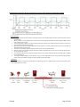
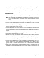
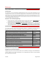
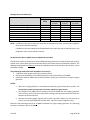
Fire Sprinkler System Leak Rates
The leak rate of a dry pipe or preaction fire sprinkler system will have direct effect on the nitrogen
generator run frequency or on/off cycles. The maximum allowable leak rate in a fire sprinkler system as
defined by NFPA-13 is 1.5 psig (.1 bar) within a 24-hour period. The design specifications of TYCO Nitrogen
Generators is based on 6.0 psig (.4 bar) leak rate within a 24-hour period. Sprinkler systems with a leak
rate in excess of 6.0 psig (.4 bar) within a 24-hour period will cause the nitrogen generator run frequency
to increase resulting in a greater wear on system components and a potential reduction in the service life
of the nitrogen generator. Sprinkler systems with a leak rate greater than 6.0 psig (.4 bar) in 24-hours
must be repaired to ensure the anticipated service life of the nitrogen generator is met.
NOTES: The run frequency of the nitrogen generator in this chart is based on nitrogen generator operation
outside of the 14-day nitrogen inerting process with the vent closed.
Excessive cycle count could indicate an air compressor/nitrogen generator short cycling issue. Contact
Johnson Controls before proceeding – visit the CONTACT US page at www.tyco-fire.com
for the contact
information by location.

TFP1273 Page 12 of 80
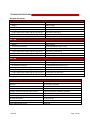
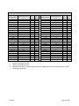
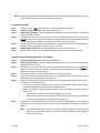
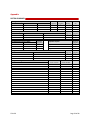
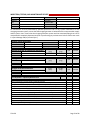
Sprinkler Leak Rate to TYCO Nitrogen Generator Run Cycle Comparison
Leak Rate
psig (bar)/24 Hr
Generator Cycle Time
Time between cycles
Hrs.
Cycles
per
Day
Cycles
per
Week
Leak Rate
psig (bar)/24 Hr
Generator Cycle Time
Time between cycles
Hrs.
Cycles
per
Day
Cycles
per
Week
1.5 (.10) *
80
< 1
3
15.0 (1.0)
8
3
21
2.0 (.14)
60
< 1
3
15.5 (1.1)
7.7
4
22
2.5 (.17)
48
< 1
4
16.0 (1.1)
7.5
4
23
3.0 (.20) ***
40
< 1
5
16.5 (1.2)
7.3
4
23
3.5 (.24)
34.3
< 1
5
17.0 (1.2)
7.1
4
24
4.0 (.28)
30
< 1
6
17.5 (1.2)
6.9
4
25
4.5 (.31)
26.7
< 1
7
18.0 (1.2)
6.7
4
25
5.0 (.35)
24
1
7
18.5 (1.3)
6.6
4
26
5.5 (.38)
21.8
2
8
19.0 (1.3)
6.3
4
27
6.0 (.41)
20
2
9
19.5 (1.3)
6.2
4
27
6.5 (.45)
18.5
2
9
20 (1.4)
6
4
28
7.0 (.48)
17.1
2
10
21 (1.4)
5.7
5
30
7.5 (.52)
16
2
11
22 (1.5)
5.5
5
31
8.0 (.55)
15
2
12
23 (1.6)
5.2
5
33
8.5 (.59)
14.1
2
12
24 (1.7)
5
5
34
9.0 (.62)
13.3
2
13
25 (1.7)
4.8
5
35
9.5 (.66)
12.6
2
14
26 (1.8)
4.6
6
37
10.0 (.69)
12
2
14
27 (1.9)
4.5
6
38
10.5 (.72)
11.4
3
15
28 (1.9)
4.3
6
39
11.0 (.76)
10.9
3
16
29 (2.0)
4.2
6
40
11.5 (.79)
10.4
3
17
30 (2.1)
4
6
42
12.0 (.83)
10
3
17
31 (2.1)
3.9
7
43
12.5 (.86)
9.6
3
18
32 (2.2)
3.8
7
45
13.0 (.90)
9.2
3
19
33 (2.3)
3.7
7
46
13.5 (.93)
8.9
3
19
34 (2.3)
3.6
7
47
14.0 (.97)
8.6
3
20
35 (2.4)
3.5
7
48
14.5 (1.0)
8.3
3
21
36 (2.5) **
3.4
8
50
* NFPA-13 Allowable leak rate.
** NFPA-25 Allowable leak rate.
*** Allowable leak rate for TYCO Nitrogen Generators. Higher leak rates may reduce the service life of
the nitrogen generator.

TFP1273 Page 13 of 80
Start-Up and Operational Procedures
INSTALLATION
Installation of the TYCO Nitrogen Generator requires five (5) steps:
1. Mount the cabinet in the appropriate location
2. Connect the dedicated power supply to the cabinet
3. Plumb the nitrogen/air supply line to the dry pipe and/or preaction sprinkler risers being served
with minimum ½” line
4. Plumb the condensate drain line to floor drain or building exterior
5. Connect nitrogen generator output signals to BMS or fire alarm system, where applicable
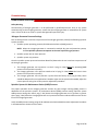
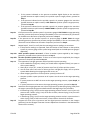
Wire Gauge Chart
1. Ensure an appropriately rated disconnect switch and circuit breaker (minimum 15 Amps and a
SCCR of 5 kVA) are installed in a suitable and accessible location in accordance with the applicable
national and/or local codes (i.e. NFPA 70).
2. The circuit breaker and disconnect are to be easily identifiable as associated with the equipment.
Ensure the ground wire is properly connected to the ground terminal(s) of the equipment using
appropriately sized ground wire.
Wire Gauge Chart
Size
Amperage
Diameter
Resistance
(AWG)
60° C (140° F)
75° C (167° F)
90° C (194° F)
(Inches)
(mm)
(Ohms / 1,000 ft)
(Ohms / km)
18
.0403
1.024
6.385
20.95
16
.0508
1.291
4.016
13.17
14
15
15
15
.0641
1.628
2.525
8.282
12
20
20
20
.0808
2.053
1.588
5.211
10
30
30
30
.1019
2.588
.9989
3.277
8
36
43
48
.1285
3.264
.6282
2.061
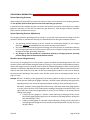
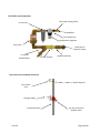
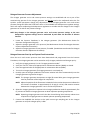
Step 1: Mounting the nitrogen generator cabinet
The TYCO Nitrogen Generator is designed to be mounted directly to the wall at the appropriate location.
Several factors should be considered in choosing the proper mounting location for the nitrogen generator:
· Access to required power supply (dedicated circuit)
· Access to sprinkler risers being supplied from nitrogen generator
· Access to drain for the condensate discharge line
· Clearance in front of the unit to open the cabinet door and for servicing the equipment
· Cleanliness of the environment and air intake
CAUTION: Nitrogen generator cabinet includes ventilation vents in the bottom and side. Ensure that all
ventilation vents are not blocked to allow proper ventilation throughout the nitrogen
generator cabinet.

TFP1273 Page 14 of 80
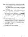
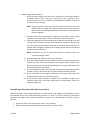
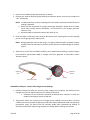
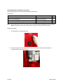
The cabinet includes a wall mounting bracket with pre-punched holes using standard anchors.
Figure 1a
NOTE: Ensure the wall is structurally sound and the cabinet is firmly anchored to a wall to support the
generator cabinet
The cabinet includes anchoring holes in the lower left and lower right corners of the cabinet using
standard anchors (See Figure 1b).
NOTE: Johnson Controls recommends that the nitrogen generator be anchored to the wall using the wall
mounting bracket and the anchoring holes in the nitrogen generator cabinet.
Figure 1b
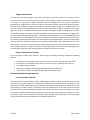
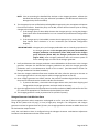
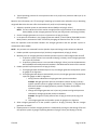
Step 2: Power Supply
The TYCO Nitrogen Generator requires a dedicated power supply to prevent interaction with other
equipment. The incoming power supply line is connected to the top of the terminal blocks inside the
nitrogen generator cabinet. The terminal connections are labeled L1, N, and G.
Required nitrogen generator power supply:
• 120VAC/1 phase/60Hz (220-240VAC/1 phase/50Hz) dedicated 20 amp circuit.
17/64” (6.75mm)
Diameter
4.00” (102mm)
22.25” (565mm) – NG-1 100/250
26.25” (667mm) – NG-1 500
9/32” (6.75mm)
Diameter
Rear Wall
Bracket
Nitrogen Generator
Cabinet

TFP1273 Page 15 of 80
Standard
E Version
Figure 2
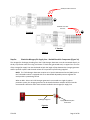
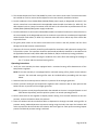
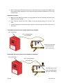
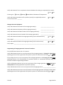
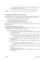
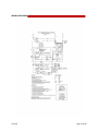
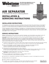
Step 3a: Plumb the Nitrogen/Air Supply Line – No Additional Air Compressor (Figure 3a)
The nitrogen/air discharge plumbing from the TYCO Nitrogen Generator must be connected directly to
the dry or preaction valve trim using a minimum ½” black steel, galvanized steel, or copper lines. The size
of the nitrogen/air supply line must be based on both the length of pipe between the nitrogen generator
and fire sprinkler systems and the total volume of fire sprinkler systems being supplied.
NOTE: The TYCO Nitrogen Generator requires an in-line Air Maintenance Device (AMD) such as
the TYCO AMD-1 which is equipped with an on-board field adjustable pressure regulator for
each sprinkler system being served.
When an NG-1 100 or NG-1 250 nitrogen generator is connected to a single dry pipe or
preaction system, the nitrogen generator can be installed without an AMD. Johnson Controls
recommends a ball valve and a check valve be installed in the nitrogen/air supply line.
Figure 3a
Air/Nitrogen Supply Line
Dry Pipe/Pre-Action System
Control Valve
Nitrogen
220-240VAC 1 Phase 50 Hz
Connections
G L1
N
120VAC/1 Phase 60 Hz Connections
G L1
N

TFP1273 Page 16 of 80
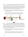
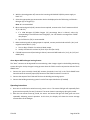
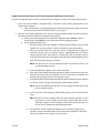
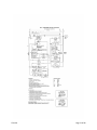
Step 3b: Plumb the Nitrogen/Air Supply Line – With Separate Air Compressor (Figure 3b)
A separate air compressor can be used to meet the NFPA 13 30-minute fill requirement or as a back up to
the nitrogen generator. In this application, the nitrogen/air discharge plumbing from the TYCO Nitrogen
Generator and the separate air compressor are connected to the dry or preaction valve trim with isolation
valves in each supply line using a minimum ½” black steel, galvanized steel, or copper lines. The size of the
nitrogen/air supply line must be based on both the length of pipe between the nitrogen generator and
fire sprinkler systems and the total volume of fire sprinkler systems being supplied.
NOTE: The TYCO Nitrogen Generator requires an in-line Air Maintenance Device (AMD) such as the
TYCO AMD-1 which is equipped with an on-board field adjustable pressure regulator for each
sprinkler system being served.
When an NG-1 100 or NG-1 250 nitrogen generator is connected to a single dry pipe or
preaction system, the nitrogen generator can be installed without an AMD. Johnson Controls
recommends a ball valve and a check valve be installed in the nitrogen/air supply line.
Figure 3b
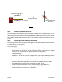
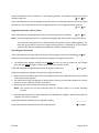
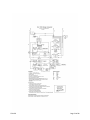
Step 3c: Plumb the Nitrogen/Air Supply Line – With House/Plant Air Supply (Figure 3c)
A separate house/plant air supply can be used as a back up to the nitrogen generator. In this application,
the nitrogen/air discharge plumbing from the TYCO Nitrogen Generator and the separate hose/plant air
supply are connected to the dry or preaction valve trim with isolation ball valves in each supply line using
a minimum ½” black steel, galvanized steel, or copper lines. The size of the nitrogen/air supply line must
be based on both the length of pipe between the nitrogen generator and fire sprinkler systems and the
total volume of fire sprinkler systems being supplied.
NOTE: The TYCO Nitrogen Generator requires an in-line Air Maintenance Device (AMD) such as the
TYCO AMD-1 which is equipped with an on-board field adjustable pressure regulator for each
sprinkler system being served.
When an NG-1 100 or NG-1 250 nitrogen generator is connected to a single dry pipe or
preaction system, the nitrogen generator can be installed without an AMD. Johnson Controls
recommends a ball valve and a check valve be installed in the nitrogen/air supply line.
Nitrogen
Isolation Ball Valve
Nitrogen Supply Line
Air/Nitrogen Supply Line
Dry Pipe/Pre-Action System
Control Valve
Air Compressor
Air Supply Line
Isolation Ball

TFP1273 Page 17 of 80
Figure 3c
Step 4: Plumb the Condensate Drain Line
The TYCO Nitrogen Generator will occasionally discharge a small amount of condensate water from the
coalescing filters inside the cabinet. It is recommended that the ¼” drain connection be plumbed to a floor
drain or building exterior. When plumbing to a drain is not feasible an evaporative collection chamber can
be used.
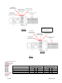
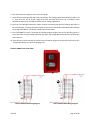
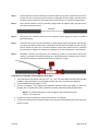
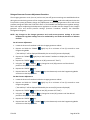
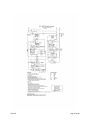
Step 5: System Signals and Monitoring, where used
The nitrogen generator cabinet has two (2) system signals and five (5) outputs that can be monitored by
the facility’s BMS or fire alarm system.
Two (2) system signals:
• Bypass Alarm - The nitrogen generator operating in the bypass mode which is activated when
the bypass valve is in the “fast fill” position to fill the fire sprinkler system and the air supplied
directly from the air compressor has reached a pressure of 20 psig (1.4 bar).
(Flashing amber light)
• Leak Monitor - The nitrogen generator is equipped with a leak monitor audible signal which is
activated when the nitrogen generator runs excessively. (Audible signal)
Five (5) system output signals for monitoring through a building monitoring system, if desired:
• Nitrogen Generator Running Mode - Form C Contacts (Energized When Running, LED On)
• Bypass Mode Alarm - Form C Contacts (Normally De-Energized, LED Off)
• Nitrogen Generator Loss of Power - Form C Contacts (Normally Energized, LED On)
• Leak Monitoring - Form C Contacts (Normally De-Energized, LED Off)
• Nitrogen System Supply Line Pressure - Analog Signal
Isolation Ball Valve
House/Plant Air Supply
Isolation Ball
Nitrogen Generator
Nitrogen Supply Line
Dry Pipe/Pre-Action System
Control Valve
Air/Nitrogen Supply Line

TFP1273 Page 18 of 80
Standard
E Version
Figure 5
Description
Normally Open Contact
Connections (i.e. Fire Alarm)
Normally Closed Contact
Connection (i.e. B.A.S.)
Relay
LED
Connections
Relay
LED
Connections
Nitrogen Generator Running Output (Running)
Energized
On
11&12
Energized
On
11&14
By-Pass Alarm Monitoring Output
De-Energized
Off
11&14
De-Energized
Off
11&12
Nitrogen Generator Power Monitoring Output
Energized
On
11&12
Energized
On
11&14
Leak Monitoring Output
De-Energized
Off
11&14
De-Energized
Off
11&12
Monitoring Relay Contact Rating
250 VAC/ 6 Amps
By-Pass Alarm
Monitoring Output
(Normally De-Energized)
Nitrogen Generator
Power Monitoring Output
(Normally Energized)
Leak Monitoring Output
(Normally De-Energized)
Nitrogen Generator
Running Output
(Energized When Running)
Nitrogen Supply Line Pressure
(Analog Signal)
By-Pass Alarm
Monitoring Output
(Normally De-Energized)
Nitrogen Generator
Power Monitoring Output
(Normally Energized)
Leak Monitoring Output
(Normally De-Energized)
Nitrogen Generator
Running Output
(Energized When Running)
Nitrogen Supply Line Pressure
(Analog Signal)
Relay Contacts – De-Energized
NC (12)
COM (11)
NO (14)
Relay Coil
A1
A2

TFP1273 Page 19 of 80
START-UP PROCEDURE
Only qualified personnel should commission the new equipment into service once it is installed. Once the
nitrogen generator has been configured, there should be no reason for re-adjusting. To start-up the
generator or to put back in service, follow these steps:
NOTE: For component locations, see Generator Configuration Diagram - Maintenance Section.
1. Verify the air maintenance devices (AMDs) have been set to the system operating or “high end”
breathing pressure.
a. Ensure AMD is calibrated to operate with nitrogen generator pressures using the Air
Maintenance Device (AMD) Pressure Adjustment Procedure in the Maintenance Section
of this manual.
b. If an NG-1 100 or 250 nitrogen generator is connected to a single dry pipe or preaction
system and an AMD is not installed, verify the nitrogen generator turn-off pressure is set
at the sprinkler system supervisory gas operating pressure.
2. Important - Verify the nitrogen generator turn-on pressure is 3-5 psig (.2-.3 bar) below the air
maintenance device set pressure/sprinkler system supervisory gas operating pressure.
3. Important - Verify the nitrogen generator turn-on pressure is 3-5 psig (.2-.3 bar) above the low
air alarm set pressure.
4. Verify the nitrogen generation/air bypass valve is nitrogen generation position.*
* The only time the nitrogen generation/air bypass valve should need to be in the “air bypass”
position is for the NFPA 13 30-min system fill time requirement.
5. Turn the cabinet power switch ON. The generator will begin filling the system with nitrogen.
NOTE: The nitrogen generator incorporates an 8-second delay upon nitrogen generator start for
protection of the integral air compressor.
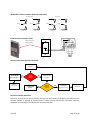
System Filling Procedure
The sprinkler system(s) can be filled using one of two filling methods based on whether the integral air
compressor of the nitrogen generator can meet the NFPA 13 30-minute fill requirement.
• Filling with Integral Air Compressor - When the sprinkler system size is within the limitations of
the nitrogen generator’s integral air compressor.
• Filling with Separate Air Compressor - When the sprinkler system size exceeds the nitrogen
generator’s integral air compressor limitations.
1. Filling with Integral Air Compressor
a. Turn the nitrogen generation/air bypass valve to the “air bypass” position.
NOTE: Bypass Alarm indicator will flash.
If an AMD is not installed, proceed to step d.
b. Open the fast fill valve and close the regulated valve of all appropriate air maintenance
devices (AMDs) necessary to fill the sprinkler system(s).
c. Close the fast fill and regulated AMD valves on any system not being filled.
d. Start the nitrogen generator.
Page is loading ...
Page is loading ...
Page is loading ...
Page is loading ...
Page is loading ...
Page is loading ...
Page is loading ...
Page is loading ...
Page is loading ...
Page is loading ...
Page is loading ...
Page is loading ...
Page is loading ...
Page is loading ...
Page is loading ...
Page is loading ...
Page is loading ...
Page is loading ...
Page is loading ...
Page is loading ...
Page is loading ...
Page is loading ...
Page is loading ...
Page is loading ...
Page is loading ...
Page is loading ...
Page is loading ...
Page is loading ...
Page is loading ...
Page is loading ...
Page is loading ...
Page is loading ...
Page is loading ...
Page is loading ...
Page is loading ...
Page is loading ...
Page is loading ...
Page is loading ...
Page is loading ...
Page is loading ...
Page is loading ...
Page is loading ...
Page is loading ...
Page is loading ...
Page is loading ...
Page is loading ...
Page is loading ...
Page is loading ...
Page is loading ...
Page is loading ...
Page is loading ...
Page is loading ...
Page is loading ...
Page is loading ...
Page is loading ...
Page is loading ...
Page is loading ...
Page is loading ...
Page is loading ...
Page is loading ...
Page is loading ...
-
 1
1
-
 2
2
-
 3
3
-
 4
4
-
 5
5
-
 6
6
-
 7
7
-
 8
8
-
 9
9
-
 10
10
-
 11
11
-
 12
12
-
 13
13
-
 14
14
-
 15
15
-
 16
16
-
 17
17
-
 18
18
-
 19
19
-
 20
20
-
 21
21
-
 22
22
-
 23
23
-
 24
24
-
 25
25
-
 26
26
-
 27
27
-
 28
28
-
 29
29
-
 30
30
-
 31
31
-
 32
32
-
 33
33
-
 34
34
-
 35
35
-
 36
36
-
 37
37
-
 38
38
-
 39
39
-
 40
40
-
 41
41
-
 42
42
-
 43
43
-
 44
44
-
 45
45
-
 46
46
-
 47
47
-
 48
48
-
 49
49
-
 50
50
-
 51
51
-
 52
52
-
 53
53
-
 54
54
-
 55
55
-
 56
56
-
 57
57
-
 58
58
-
 59
59
-
 60
60
-
 61
61
-
 62
62
-
 63
63
-
 64
64
-
 65
65
-
 66
66
-
 67
67
-
 68
68
-
 69
69
-
 70
70
-
 71
71
-
 72
72
-
 73
73
-
 74
74
-
 75
75
-
 76
76
-
 77
77
-
 78
78
-
 79
79
-
 80
80
-
 81
81


Tyco NG-1 100 / NG-1 250 / NG-1 500 Installation guide
- Category
- Fire protection
- Type
- Installation guide
Ask a question and I''ll find the answer in the document
Finding information in a document is now easier with AI
Related papers
-
Tyco NG-1 100 / NG-1 250 / NG-1 500 Installation guide
-
-
-
-
-
-
-
-
-
Other documents
-
Melnor 9520 Installation guide
-
 AXIOMET AX-3020L User manual
-
Wirepath PLUG-RJ45-CAT6 Owner's manual
-
 H2oEliteLabs EWCLD User manual
-
Potter PNA Portable Nitrogen Analyzer Owner's manual
-
 Pneumatech PMNG Series Installation, Operation & Maintenance Manual
-
Graco 320553EN-A User manual
-
 NIBCO Webstone AIR SEPARATOR Installation & Servicing Instructions
-
 Webstone, a brand of NIBCO 74004 Installation guide
-
Toro 830S Series User manual


