Page is loading ...

Operating Instructions
VEGADIS 176
External indicating and adjustment display
without external energy for front panel
mounting
Document ID: 47916

2
Contents
VEGADIS 176 • External indicating and adjustment display without external energy for front panel mounting
47916-EN-210421
Contents
1 About this document ............................................................................................................... 4
1.1 Function ........................................................................................................................... 4
1.2 Target group ..................................................................................................................... 4
1.3 Symbols used................................................................................................................... 4
2 For your safety ......................................................................................................................... 5
2.1 Authorised personnel ....................................................................................................... 5
2.2 Appropriate use ................................................................................................................ 5
2.3 Warning about incorrect use ............................................................................................. 5
2.4 General safety instructions ............................................................................................... 5
2.5 Safety label on the instrument .......................................................................................... 5
2.6 EU conformity ................................................................................................................... 5
2.7 NAMUR recommendations .............................................................................................. 6
2.8 Environmental instructions ............................................................................................... 6
3 Product description ................................................................................................................. 7
3.1 Conguration .................................................................................................................... 7
3.2 Principle of operation........................................................................................................ 7
3.3 Indication and adjustment ................................................................................................ 7
3.4 Packaging, transport and storage ..................................................................................... 8
4 Mounting ................................................................................................................................... 9
4.1 Mounting location, installation position ............................................................................. 9
4.2 Mounting preparations ..................................................................................................... 9
4.3 Installation procedure ....................................................................................................... 9
5 Connect to the signal circuit ................................................................................................. 10
5.1 Preparing the connection ............................................................................................... 10
5.2 Connection technology and steps .................................................................................. 10
5.3 Wiring plan ..................................................................................................................... 10
5.4 Connection examples ..................................................................................................... 12
5.5 Switch-on phase............................................................................................................. 13
6 Setup ....................................................................................................................................... 14
6.1 Indication and adjustment .............................................................................................. 14
6.2 Parameter adjustment - Menu Setup .............................................................................. 15
6.3 Parameter adjustment - Menu Diagnosis ....................................................................... 16
6.4 Parameter adjustment - Menu Expert ............................................................................. 16
7 Maintenanceandfaultrectication ...................................................................................... 18
7.1 Maintenance .................................................................................................................. 18
7.2 Rectify faults ................................................................................................................... 18
7.3 How to proceed if a repair is necessary .......................................................................... 19
8 Dismount................................................................................................................................. 21
8.1 Dismounting steps.......................................................................................................... 21
8.2 Disposal ......................................................................................................................... 21
9 Supplement ............................................................................................................................ 22
9.1 Technical data ................................................................................................................ 22
9.2 Dimensions .................................................................................................................... 23
9.3 Industrial property rights ................................................................................................. 24

3
Contents
VEGADIS 176 • External indicating and adjustment display without external energy for front panel mount-
ing
47916-EN-210421
Safety instructions for Ex areas
TakenoteoftheExspecicsafetyinstructionsforExapplications.
These instructions are attached as documents to each instrument
with Ex approval and are part of the operating instructions.
Editing status: 2021-04-20

4
1 About this document
VEGADIS 176 • External indicating and adjustment display without external energy for front panel mounting
47916-EN-210421
1 About this document
1.1 Function
This instruction provides all the information you need for mounting,
connection and setup as well as important instructions for mainte-
nance,faultrectication,theexchangeofpartsandthesafetyofthe
user. Please read this information before putting the instrument into
operation and keep this manual accessible in the immediate vicinity
of the device.
1.2 Target group
This operating instructions manual is directed to trained personnel.
Thecontentsofthismanualmustbemadeavailabletothequalied
personnel and implemented.
1.3 Symbols used
Document ID
This symbol on the front page of this instruction refers to the Docu-
ment ID. By entering the Document ID on www.vega.com you will
reach the document download.
Information, note, tip: This symbol indicates helpful additional infor-
mation and tips for successful work.
Note: This symbol indicates notes to prevent failures, malfunctions,
damage to devices or plants.
Caution: Non-observance of the information marked with this symbol
may result in personal injury.
Warning: Non-observance of the information marked with this symbol
may result in serious or fatal personal injury.
Danger: Non-observance of the information marked with this symbol
results in serious or fatal personal injury.
Ex applications
This symbol indicates special instructions for Ex applications.
•
List
The dot set in front indicates a list with no implied sequence.
1 Sequence of actions
Numbers set in front indicate successive steps in a procedure.
Battery disposal
This symbol indicates special information about the disposal of bat-
teries and accumulators.

5
2 For your safety
VEGADIS 176 • External indicating and adjustment display without external energy for front panel mount-
ing
47916-EN-210421
2 For your safety
2.1 Authorised personnel
All operations described in this documentation must be carried out
onlybytrained,qualiedpersonnelauthorisedbytheplantoperator.
During work on and with the device, the required personal protective
equipment must always be worn.
2.2 Appropriate use
The VEGADIS 176 is used for separate measured value indication of
all standardized 4 … 20 mA circuits
2.3 Warning about incorrect use
Inappropriate or incorrect use of this product can give rise to applica-
tion-specichazards,e.g.vesseloverllthroughincorrectmounting
or adjustment. Damage to property and persons or environmental
contamination can result. Also, the protective characteristics of the
instrument can be impaired.
2.4 General safety instructions
This is a state-of-the-art instrument complying with all prevailing
regulations and directives. The instrument must only be operated in a
technicallyawlessandreliablecondition.Theoperatorisresponsi-
ble for the trouble-free operation of the instrument. When measuring
aggressive or corrosive media that can cause a dangerous situation
if the instrument malfunctions, the operator has to implement suitable
measures to make sure the instrument is functioning properly.
The safety instructions in this operating instructions manual, the na-
tional installation standards as well as the valid safety regulations and
accident prevention rules must be observed by the user.
For safety and warranty reasons, any invasive work on the device
beyond that described in the operating instructions manual may be
carried out only by personnel authorised by the manufacturer. Arbi-
traryconversionsormodicationsareexplicitlyforbidden.Forsafety
reasons,onlytheaccessoryspeciedbythemanufacturermustbe
used.
To avoid any danger, the safety approval markings and safety tips on
the device must also be observed.
2.5 Safety label on the instrument
The safety approval markings and safety tips on the device must be
observed.
2.6 EU conformity
ThedevicefullsthelegalrequirementsoftheapplicableEUdirec-
tives.ByaxingtheCEmarking,weconrmtheconformityofthe
instrument with these directives.
The EU conformity declaration can be found on our homepage.

6
2 For your safety
VEGADIS 176 • External indicating and adjustment display without external energy for front panel mounting
47916-EN-210421
2.7 NAMUR recommendations
NAMUR is the automation technology user association in the process
industry in Germany. The published NAMUR recommendations are
acceptedasthestandardineldinstrumentation.
ThedevicefullstherequirementsofthefollowingNAMURrecom-
mendations:
•
NE 21 – Electromagnetic compatibility of equipment
•
NE 43 – Signal level for fault information from measuring transduc-
ers
For further information see www.namur.de.
2.8 Environmental instructions
Protection of the environment is one of our most important duties.
That is why we have introduced an environment management system
with the goal of continuously improving company environmental pro-
tection.Theenvironmentmanagementsystemiscertiedaccording
to DIN EN ISO 14001.
Pleasehelpusfullthisobligationbyobservingtheenvironmental
instructions in this manual:
•
Chapter " Packaging, transport and storage"
•
Chapter " Disposal"

7
3 Product description
VEGADIS 176 • External indicating and adjustment display without external energy for front panel mount-
ing
47916-EN-210421
3 Product description
3.1 Conguration
The scope of delivery encompasses:
•
Indication and adjustment display VEGADIS 176
•
Mounting material
•
Documentation
– This operating instructions manual
– Exspecicsafetyinstructions(withExversions),ifnecessary
furthercerticates
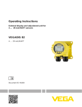
3.2 Principle of operation
The VEGADIS 176 is an external indicating and adjustment display
without additional external energy for front panel mounting. It is used
for separate measured value indication of all standardized 4 … 20 mA
circuits.AnexistingHARTsignalwillnotbeinuenced(HART-trans-
parent).
The instrument is looped directly into the 4 … 20 mA circuit and
requires no separate power supply.
3
4
1
2
Fig. 1: Connection of VEGADIS 176 to a sensor
1 Voltage supply/Signal output sensor
2 VEGADIS 176
3 4 … 20 mA signal cable
4 Sensor
3.3 Indication and adjustment
The VEGADIS 176 is equipped with a 5-digit, scalable LC display.
Apart from the digital measured value, parameter adjustment of an
analogue bargraph and the unit is also possible. If required, back-
ground lighting can be activated by selecting the corresponding
terminals.
Adjustment is carried out via three keys in the front plate of the instru-
ment.
Scope of delivery
Application area

8
3 Product description
VEGADIS 176 • External indicating and adjustment display without external energy for front panel mounting
47916-EN-210421
3.4 Packaging, transport and storage
Your instrument was protected by packaging during transport. Its
capacity to handle normal loads during transport is assured by a test
based on ISO 4180.
The packaging of standard instruments consists of environment-
friendly, recyclable cardboard. For special versions, PE foam or PE
foil is also used. Dispose of the packaging material via specialised
recycling companies.
Transport must be carried out in due consideration of the notes on the
transport packaging. Nonobservance of these instructions can cause
damage to the device.
The delivery must be checked for completeness and possible transit
damage immediately at receipt. Ascertained transit damage or con-
cealed defects must be appropriately dealt with.
Up to the time of installation, the packages must be left closed and
stored according to the orientation and storage markings on the
outside.
Unless otherwise indicated, the packages must be stored only under
the following conditions:
•
Not in the open
•
Dry and dust free
•
Not exposed to corrosive media
•
Protected against solar radiation
•
Avoiding mechanical shock and vibration
•
Storage and transport temperature see chapter " Supplement -
Technical data - Ambient conditions"
•
Relative humidity 20 … 85 %
Withinstrumentweightsofmorethan18kg(39.68lbs)suitableand
approved equipment must be used for lifting and carrying.
Packaging
Transport
Transport inspection
Storage
Storage and transport
temperature
Lifting and carrying

9
4 Mounting
VEGADIS 176 • External indicating and adjustment display without external energy for front panel mount-
ing
47916-EN-210421
4 Mounting
4.1 Mounting location, installation position
The instrument is designed for use in a front panel. The installation
position is horizontal.
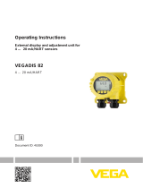
4.2 Mounting preparations
Preparepanelcut-out92x45mm(3.62x1.77in)accordingtoillus-
trationandDIN43700.Max.panelthickness13mm(0.51inch)
92mm (3
5
/
8
")
45 mm
(1.77")
92 mm
(3.62")
Required tools:
•
Slot screwdriver
4.3 Installation procedure
Proceed as follows:
1. Insert the instrument into the opening from the front
1 2
3
2. Attach mounting clips to the side of the housing
3. Tightenthethreadedrodsevenlywiththescrewdriver(max.
torque0.6Nm)

10
5 Connect to the signal circuit
VEGADIS 176 • External indicating and adjustment display without external energy for front panel mounting
47916-EN-210421
5 Connect to the signal circuit
5.1 Preparing the connection
Always keep in mind the following safety instructions:
•
Connect only in the complete absence of line voltage
•
Only connect to a 4 … 20 mA signal circuit with sensor or the
4 … 20 mA signal output of a controller
The instrument must only be powered by an energy-limited circuit
according to IEC 61010-1.
Caution:
Never connect the VEGADIS 176 directly to a voltage source without
current limitation. Otherwise the instrument can be destroyed by a too
high current.
5.2 Connection technology and steps
The voltage supply and signal output are connected via the spring-
loaded terminals in the housing.
Proceed as follows:
1. Removeapprox.10cm(4in)ofthecablemantle,stripapprox.
1cm(0.4in)ofinsulationfromtheendsoftheindividualwires
2 3
Fig. 2: Connection steps 2 and 3
2. Solidcoresaswellasexiblecoreswithcableendsleevesare
inserted directly into the terminal openings.
3. Incaseofexiblecoreswithoutendsleeves,presstheterminal
from above with a small screwdriver, the terminal opening is then
free. When the screwdriver is released, the terminal closes again.
Information:
Youcanndfurtherinformationonthemax.wirecross-sectionunder
" Technical data - Electromechanical data".
4. Check the hold of the wires in the terminals by lightly pulling on
them
5. Connect screen to the potential equalisation terminal.
5.3 Wiring plan
The terminals are on the rear of the housing.
Safety instructions
Voltage supply
Connection technology
Connection procedure
Terminal assignment

11
5 Connect to the signal circuit
VEGADIS 176 • External indicating and adjustment display without external energy for front panel mount-
ing
47916-EN-210421
13245
Fig. 3: Terminal assignment VEGADIS 176
Terminal Function Polarity Notes
1 Output, sensor + Display with backlight
Connection active
4 … 20 mA circuit
-
2 Output, sensor + Display without backlight
Connection active
4 … 20 mA circuit
-
3 Output, sensor - Bridged internally with
terminal 4
4 Input voltage supply - Bridged internally with
terminal 3
5 Input voltage supply +
Connection active
4 … 20 mA circuit
+
The terminal for function ground is also on the rear of the instrument.
We recommend connecting it to the potential equalization for EMC
reasons.
1
Fig. 4: Connection to function ground with VEGADIS 176
1 Connecting lug for function ground
1
2
+
–
–
+
13245
Fig. 5: Wiring plan VEGADIS 176 to passive sensors
1 To the sensor
2 To voltage supply or processing system
Function ground
Passive sensors

12
5 Connect to the signal circuit
VEGADIS 176 • External indicating and adjustment display without external energy for front panel mounting
47916-EN-210421
1
2
+
–
–
+
13245
Fig. 6: Wiring plan VEGADIS 176 to passive sensors, with backlight
1 To the sensor
2 To voltage supply or processing system
1
+
–
13245
Fig. 7: Wiring plan VEGADIS 176 to active sensors or controllers
1 To the sensor
1
+
–
13245
Fig. 8: Wiring plan VEGADIS 176 to active sensors or controllers, with backlight
1 To the sensor
5.4 Connection examples
1
2
3
5
1
2
+
( )
(-)
678
4...20mA
13245
Fig. 9: Connection example VEGADIS 176, 4 … 20 mA sensor
1 Voltage supply
2 VEGADIS 176
3 Sensor
Passive sensors with
backlight
Active sensors, control-
lers
Active sensors or control-
lers with backlight
Connection to signal
circuit

13
5 Connect to the signal circuit
VEGADIS 176 • External indicating and adjustment display without external energy for front panel mount-
ing
47916-EN-210421
5
1
2
+
( )
(-)
678
4...20mA
2
1
6
4
3 5
13245
+
-
1
2
3
4
18 1716 15 1413 1211 10 9 8
7
6 5
N L
-+
+
-
on
1
2
1
2
3
4
%
Fig. 10: Connection of the VEGADIS 176 as external indication to controller or
four-wire sensor
1 Voltage supply
2 Controller
3 Input, controller (sensor circuit)
4 Sensor
5 Output, controller (indicating circuit)
6 VEGADIS 176
5.5 Switch-on phase
After connecting the sensors to VEGADIS 176 and the voltage supply
or after voltage recovery, the instrument carries out a self-check for
approx. 10 s and then displays the following:
•
All display segments
•
Firmware version, e.g. 1.02.00
•
Status message, e.g. S901
Thentheactualmeasuredvalueisdisplayed.Youcanndfurther
information on the display in chapter " Parameter adjustment - Menu
Setup".
Connection to controllers

14
6 Setup
VEGADIS 176 • External indicating and adjustment display without external energy for front panel mounting
47916-EN-210421
6 Setup
6.1 Indication and adjustment
1
2
3
4
7
6
5
Fig. 11: Display and adjustment elements of VEGADIS 176
1 Symbol: adjustment menu locked
2 Symbol: error
3 Symbol: upper/lower range
4 Adjustment keys
5 14-segment display for unit/TAG
6 Bargraph with marks for lower and upper range
7 5-digit, 7-segment display for measured value
The adjustment is carried out via three buttons on the housing front.
Key Function
Adjustment key
•
Invoke the adjustment menu
•
Conrmselection
•
Adjustment of parameters in the adjustment menu
Plus/minus buttons
•
Selection and adjustment/change of values in the adjust-
ment menu
•
Pushing " -" and " +" simultaneously will cause a reset to
the nixt higher menu level without saving the adjusted value
(ESC)
The device setup can be locked with a 4-digit user code. When the
setup is locked, a lock symbol is displayed when invoking an adjust-
ment parameter.
The adjustment functions of the process indicator are ordered in
the following menus. The individual parameters and settings are
described in the following chapters " Parameter adjustment".
The 7-segment display can only display numbers, not alphanumeric
characters.Hence,theprocedureforenteringnumbersisdierent
from that for text parameters.
Number parameters
If an adjustment position contains only numbers as a parameter, the
adjustment position itself is shown in the 14-segment display and the
Display and adjustment
elements
Adjustment system

15
6 Setup
VEGADIS 176 • External indicating and adjustment display without external energy for front panel mount-
ing
47916-EN-210421
set parameter in the 7-segment display. Press the " OK" key to edit
and then enter the user code.
Text parameters
Iftheadjustmentpositioncontainstextparameters,atrstonlythe
adjustment position is displayed in the 14-segment display. After the "
OK" key is pressed again, the set parameter is shown in the 14-seg-
ment display. To edit, press the " +" key and then enter the user code.
Return
A return is carried out:
•
At the end of the individual menus and menu points, return to the
next higher menu level by pressing " Back" and the " OK" key
•
Pressing " -" and " +"simultaneously(seetableabove)bringsthe
user to the next higher menu level, and so on up to the measured
value indication
•
10 minutes after the last pressing of a key, the display automati-
cally jumps back to measured value indication
In all cases, the EXPRT menu is again locked.
Note:
If the adjustment menu is locked by a user code, the individual menus
andparameterscanbedisplayedbutnotmodied.Tomodifyapa-
rameter, the user code has to be entered.
The following table shows the menu structure:
Menu Function Description
SETUP Setup Fundamental device settings
DIAG Diagnostics Device information, indication of error
messages
EXPRT Expert Expert settings for device setup. Edit-
ing in the menu Expert is protected by
anaccesscode(default0000).
6.2 Parameter adjustment - Menu Setup
In this menu item you specify the number of decimal places for the
indication.
Value range: 0 DEC, 1 DEC, 2 DEC, 3 DEC, 4 DEC
Inthismenuitemyouspecifythe5-digitnumbervalue(numberof
decimalplacesassetunderDECIM)forthescalingofthemeasured
value at 4 mA.
Example: SC__4 = 0.0 means display 0.0 with measurement current
4 mA. The unit selected under UNIT is used in the display.
Value range: -19 999 … 99 999
Inthismenuitemyouspecifythe5-digitnumbervalue(numberof
decimalplacesassetunderDECIM)forthescalingofthemeasured
value at 20 mA.
Adjustment menu
Setup - DECIM
Setup - SC__4
Setup - SC__20

16
6 Setup
VEGADIS 176 • External indicating and adjustment display without external energy for front panel mounting
47916-EN-210421
Example: SC__20 = 100.0 means display 100.0 with measurement
current 20 mA. The unit selected under UNIT is used in the display.
Value range: -19 999 … 99 999
In this menu item you select the unit for the display. By setting "
USER",auser-denedunitcanbeenteredinparameter"TEXT".
Value range: %, °C, °F, K, USER
By setting " USER" in " UNIT",auser-denedunitcanbeentered.
Value range: Free text, 5 characters
6.3 Parameter adjustment - Menu Diagnosis
Inthismenuitem,actuallyoccurringdiagnosticmessages(Actual
Error)aredisplayed.Ifseveralmessagesoccuratthesametime,the
message with the highest priority is displayed.
Inthismenuitem,thelastdiagnosticmessage(LastError)withthe
highest priority is displayed.
Inthismenuitem,thermwareversionisdisplayed.
6.4 Parameter adjustment - Menu Expert
The menu Expert also contains, in addition to all menu items from the
menu Setup, the submenus and menu items described here. When
theExpertmenuisinvoked,theusercodeisrequested(UCODE,
Default:0000).
Instrumentsetupcanbeprotectedagainstunauthorizedmodication
by means of the user code. If setup is locked, the lock symbol is dis-
played when an adjustment parameter is invoked. With default setting
" 0000", the user code is not active, i.e. parameters in the setup can
bemodiedwithoutenteringthecode.TogainaccesstotheExpert
menu, the code always has to be entered, even when the default set-
tings are active.
Value range: 0000 … 9999
Resetting the instrument setup to default values.
Byselecting"YES"andconrmingwiththe"OK" key, the instrument
is reset.
Value range: YES, NO
The following table shows the default values after a reset:
Setup - UNIT
Setup - TEXT
Diagnosis - AERR
Diagnosis - LERR
Diagnosis - FWVER
SYSTM - UCODE
SYSTM - FRSET

17
6 Setup
VEGADIS 176 • External indicating and adjustment display without external energy for front panel mount-
ing
47916-EN-210421
Menu Submenu Menu item Default values
SETUP - DECIM 1 DEC
- SC__4 0.0
- SC__20 100.0
- UNIT %
- TEXT -
EXPRT SYSTM UCODE 0000
FRSET NO
INPUT DECIM 1 DEC
SC__4 0.0
SC__20 100.0
UNIT %
TEXT -
CURVE LINAR
NAMUR YES
RNGLO 03.80
RNGHI 20.00
OFFST 0.0
Selection of the linearization curve for the measurement current. With
this parameter the instrument can be adapted to a linear or a square
root characteristic to the measurement signal.
Value range: LINAR, SQRT
SpecicationoftheerrorlimitsaccordingtostandardNAMURNE43
Value range: YES, NO
Lower range limit. If the measured current falls below this limit, an
error message is output.
Only visible with NAMUR = NO
Value range: 00.00 … 99.99
Upper range limit. If the measured current exceeds this limit, an error
message is output.
Only visible with NAMUR = NO
Value range: 00.00 … 99.99
Enteringanosetvalueforindicationofthemeasuredvalue.
Value range: --19999 … 99999
INPUT-CURVE
INPUT-NAMUR
INPUT-RNGLO
INPUT-RNGHI
INPUT-OFFST

18
7Maintenanceandfaultrectication
VEGADIS 176 • External indicating and adjustment display without external energy for front panel mounting
47916-EN-210421
7 Maintenanceandfaultrectication
7.1 Maintenance
If the device is used properly, no special maintenance is required in
normal operation.
The cleaning helps that the type label and markings on the instrument
are visible.
Take note of the following:
•
Use only cleaning agents which do not corrode the housings, type
label and seals
•
Use only cleaning methods corresponding to the housing protec-
tion rating
7.2 Rectify faults
Thedeviceoersmaximumreliability.Nevertheless,faultscanoccur
during operation. These may be caused by the following, e.g.:
•
Sensor
•
Process
•
Voltage supply
•
Signal processing
Therstmeasuretobetakenistocheckthesensoroutputsignal
according to the operating instructions of the respective sensor. In
many cases, the causes can be determined and faults can be quickly
rectied.
Error code Cause Rectication
4 … 20 mA sig-
nal missing
Wrong connection to
voltage supply
Check and correct, if necessary,
according to chapter " Wiring
plan"
No power supply Check cables for breaks; repair if
necessary
Operating voltage too
low or load resistance
too high
Check, adapt if necessary
The instrument can be adjusted to error limits according to NAMUR
NE 43. If one of these values is violated, then the instrument displays
a diagnosis code.
Error limit with current
value I
Error Diagnosis code
I≤3.6mA Lower range F100
3.6mA<I≤3.8mA Unpermitted measured
value
S901
Maintenance
Cleaning
Causes of malfunction
Faultrectication
Check the 4 … 20 mA
signal
Error limits - NAMUR
NE 43

19
7Maintenanceandfaultrectication
VEGADIS 176 • External indicating and adjustment display without external energy for front panel mount-
ing
47916-EN-210421
Error limit with current
value I
Error Diagnosis code
20.5mA≤I<21.0mA Unpermitted measured
value
S902
I > 21 mA Upper range F100
The instrument is equipped with diagnostic functions for the sensor. If
an error is detected, the instrument displays a diagnostic code.
Diagnosis code Short text Recticationmeasure
F100 Sensor error
•
Check electrical wiring
•
Check sensor
•
Check sensor parameter adjustment
S901 Input signal too
low
•
Check sensor output for defects and
deviation from normal character-
istics
•
Check sensor parameter adjustment
S902 Input signal too
large
The instrument has diagnostic functions for its own electronics. If an
error is detected, a diagnostic message is displayed.
Diagnosis code Short text Recticationmeasure
F261 Electronics mod-
ule
Replace electronics
F283 Memory content
•
Restart instrument
•
Carry out device reset
•
Replace electronics
F431 Factory calibration Replace electronics
Diagnosis code Short text Recticationmeasure
M561 Display exceeded Check scaling
Should these measures not be successful, please call in urgent cases
the VEGA service hotline under the phone no. +49 1805 858550.
Thehotlineismanned7daysaweekround-the-clock.Sinceweoer
this service worldwide, the support is only available in the English
language. The service is free, only standard call charges are incurred.
Depending on the reason for the fault and the measures taken, the
steps described in chapter " Setup" must be carried out again or must
be checked for plausibility and completeness.
7.3 How to proceed if a repair is necessary
Youcanndaninstrumentreturnformaswellasdetailedinformation
about the procedure in the download area of our homepage. By doing
this you help us carry out the repair quickly and without having to call
back for needed information.
Sensor diagnosis
Electronics diagnosis
Congurationdiagnosis
24 hour service hotline
Reaction after fault recti-
cation

20
7Maintenanceandfaultrectication
VEGADIS 176 • External indicating and adjustment display without external energy for front panel mounting
47916-EN-210421
In case of repair, proceed as follows:
•
Printandlloutoneformperinstrument
•
Clean the instrument and pack it damage-proof
•
Attach the completed form and, if need be, also a safety data
sheet outside on the packaging
•
Ask the agency serving you to get the address for the return ship-
ment.Youcanndtheagencyonourhomepage.
/