AMAZON COMMERCIAL 6000 Count Compact User manual
- Category
- Multimeters
- Type
- User manual

6000 Count Compact Digital Multimeter, IP67, True rms,
CATIV600V
Multímetro Digital Compacto de 6000 Cuentas,
conTemperatura, IP67, True RMS, CAT IV, 600V
Multimètre Numérique Compact, Indice IP67 de Température,
à Valeur Efficace Vraie, CAT IV 600V, Écran (6000Comptes)
B07W1BL3RH

English . . . . . . . . . . . . . . . . . . . . . . . 3
Español . . . . . . . . . . . . . . . . . . . . . 44
Français . . . . . . . . . . . . . . . . . . . . . 90

3
EN
IMPORTANT
SAFEGUARDS
Read these instructions carefully and
retain them for future use. If this product
is passed to a third party, then these
instructions must be included.
When using electrical appliances, basic safety
precautions should always be followed to reduce
the risk of fire, electric shock, and/or injury to
persons including the following:
WARNING
Risk of electric shock! Improper
use of this product can cause damage, shock,
injury or death.
WARNING
Risk of electric shock! The safety
features of this product may not protect the user if
not used in accordance with this user manual.
WARNING
Risk of electric shock! Take
special care while working under wet conditions.
Humid objects and air have an increased conductivity.
CAUTION
Risk of short circuit! Use the test
probe shrouds to avoid accidental short circuiting
if the components or test points are too near each
other. Operation is limited to CAT II applications
when the insulated tips are removed from one
or both test probes. Refer to Specification in this
manual for maximum voltage ratings.

4
EN
WARNING
Risk of electric shock! Use
special care when making measurements, if the
voltages are greater than 25V~ rms or 35V .
These voltages are considered a shock hazard.
WARNING
Risk of electric shock! Keep
fingers away from the metal probe tips when taking
measurements.
WARNING
Risk of explosion! Do not use
the product near explosive vapors, dust or gases.
CAUTION
Risk of injury! The probe tips are
sharp for accuracy. Be careful when handling and
reattach the probe tip shrouds after use.
• This product is intended for origin of installation
use and protected, against and the users,
by double insulation per EN61010-1 and
IEC61010-1 2nd edition (2001) to CAT IV
600V and CAT III 1000V; Pollution Degree
2. The product also meets UL 61010-1, 2
nd
edition (2004), CAN/CSA C22.2 No. 61010-1
2
nd
edition (2004), and UL 61010B-2-031, 1
st
edition (2003).
• This product must be used by trained
usersonly.
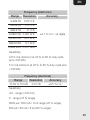
• Do not exceed the maximum allowable input
range of any measurement mode.

5
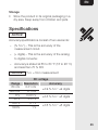
EN
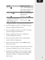
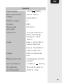
Mode Maximum Input
A~, A 10 A, 1000V fast acting
fuse (max. 30seconds
every 15minutes)
mA~, mA 800 mA, 1000V fast
acting fuse
V~, V 1000 V~ rms/
Frequency, Resistance,
Capacitance, Diode
Test, Continuity
250 V~ rms /
Surge Protection: 8 kV peak per IEC 61010
• Do not measure current on a CAT III circuitry
whose voltage exceeds 1000 V.
• Do not measure current on a CAT IV circuitry
whose voltage exceeds 600 V.
• When measuring volts, do not switch to
current/resistance modes.
• Set the function switch to the appropriate
position before measuring.
• Set the function switch to the OFF position
when not in use.
• When changing ranges always disconnect the
connector leads from the circuit under test.
• Inspect the condition of the connector leads
and the product itself for any damage before
operation. Repair or replace any damage
before use.

6
EN
• Verify the product’s proper operation before use
by measuring a known live voltage.
• Always discharge capacitors and remove
power from the device under test before
performing diode, resistance or continuity tests.
• Voltage checks on electrical outlets can
be difficult and misleading because of the
uncertainty of connection to the recessed
electrical contacts. Do not use this product
for checking socket outlets. Use special
equipment for checking socket outlets.
• Do not use, if the product seems to be
damaged or if it is not working properly.
If in doubt, replace the product.
• Comply with all applicable safety codes. Use
approved personal protective equipment when
working near live circuits − especially with
regard to the possibility of arc flash hazards.
• Do not attempt repairs. There are no user
serviceable parts.
• When working in wet conditions, always attach
the rain caps onto the open input jacks.
• Always remove the connector leads before
replacing the battery or fuses.

7
EN
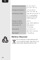
Battery Warnings
• Always insert batteries correctly with regards
to polarity (+ and –) marked on the battery and
the product.
• Exhausted batteries should be immediately
removed from product and properly disposed.
• Keep batteries out of the reach of children.
• Do not dispose of batteries in fire.
• Remove batteries from product if it is not to be
used for an extended period of time.
• If the battery leaks, avoid contact with skin and
eyes. Rinse affected areas immediately with
plenty of clean water, then consult a doctor.
Explanation of Symbols
WARNING
The signal word that indicates
a hazard with a medium level of
risk which, if not avoided, could
result in death or serious injury.
CAUTION
The signal word that indicates a
hazard that if not prevented could
result in minor or moderate injury.
NOTICE
Indicates a practical tip, advice
or practice not related to
personal injury.

8
EN
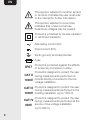
This symbol, adjacent to another symbol
or terminal, indicates the user must refer
to the manual for further information.
This symbol, adjacent to a terminal,
indicates that, under normal use,
hazardous voltages may be present.
Product is protected by double insulation
or reinforced insulation.
Alternating current (AC).
Direct current (DC).
Earth (ground) terminal/potential.
Fuse
IP67
Product is protected against the effects
of temporary immersion in water.
CAT II
1000V
Product is designed to protect the user
during measurements performed on
circuits directly connected to the low
voltage installation.
CAT III
1000V
Product is designed to protect the user
during measurements performed in the
building installation (up to 1000 V).
CAT IV
600V
Product is designed to protect the user
during measurements performed at the
source of low-voltage installation
(up to 600 V).

9
EN
Intended Use
• This product is intended to perform electrical
measurements on CAT III locations (3-phase
and single phase distribution) and CAT IV
locations (3-phase and single phase primary
over-current protection devices).
• This product covers CAT II and CAT I locations.
• This product may be used only under the
conditions and for the purposes for which it
was designed.
• No liability will be accepted for damages
resulting from improper use or non-compliance
with these instructions.
Before First Use
• Check the product for transport damages.
• Remove all the packing materials.
DANGER
Risk of suffocation! Keep
any packaging materials away from children –
thesematerials are a potential source of danger,
e.g. suffocation.

10
EN
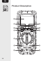
Product Description
A
B
C
D
E
F
G
H
I
J
K
L

11
EN
A
Display
K
Positive input
jack
B
MAX/MIN button
L
COM input jack
C
RANGE button
M
Probe tip shrouds
D
MODE button
N
Test probes with
connector leads
E
Function switch
O
Rain caps
F
10A input jack
P
Thermocouple probe
adapter with caps
G
uA/mA input jack
Q
Thermocouple probe
H
RELATIVE button
R
Battery
compartment
I
Hz/% button
S
Tilt stand
J
HOLD / button
T
Test probe holders
S
R
N
O
P
T
M
Q

12
EN
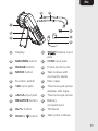
1
H Display hold
9
Relative
2
Units of
measurement
10
Continuity
3
% Percent
(duty cycle)
11
Diode test
4
Low battery
indicator
12
Minus sign
5
Auto power-off
13
AC Alternating
current/voltage
6
Display reading
14
DC Direct
current/voltage
7
Auto Range
indicator
15
VFD Variable
frequency drive mode
8
MAX-MIN indicator
13
14
12
11
10
15
1 2 3 4
5
6
789

13
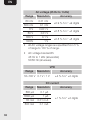
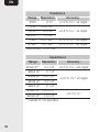
EN
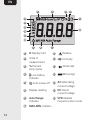
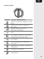
Function switch
Position Function / Measurement
AC/DC current(µA) / frequency/ duty
cycle
AC/DC current(mA) / frequency/
duty cycle
AC/DC current up to 10 A/
frequency/ duty cycle
OFF
AC voltage / frequency / duty cycle /
variable frequency drive mode
DC voltage
AC/DC voltage (mV) / frequency /
duty cycle
Resistance / diode test / continuity /
capacitance
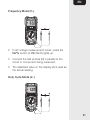
Frequency / duty cycle
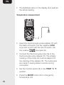
Temperature

14
EN
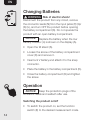
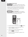
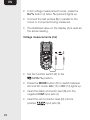
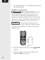
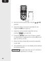
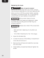
Changing Batteries
WARNING
Risk of electric shock!
Disconnect the product from any circuit, remove
the connector leads (N) from the input jacks (F)/(G)/
(K)/(L), and turn OFF the product before opening
the battery compartment (R). Do not operate the
product with an open battery compartment.
NOTICE
Replace the battery when the low
battery indicator (4) is shown on the display (A).
• Open the tilt stand (S).
• Loosen the screw of the battery compartment
cover (R) and remove it.
• Insert a 9 Vbattery and attach it to the snap
connector.
• Place the battery in the battery compartment(R).
• Close the battery compartment (R) and tighten
the screw.
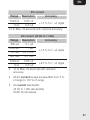
Operation
NOTICE
Keep the protection plugs of the
connector leads and reattach after use.
Switching the product on/off
• To switch the product on, set the function
switch (E) to the desired measurement mode.

15
EN
• To switch the product off, set the function
switch (E) to the OFF position.
Automatic power OFF
• In order to conserve battery life, the product
automatically emits a beeping signal that the
product has been idle for 15 minutes. Right
after 1 minute, the product turns off.
• To turn the product on again, press any button.
• When “automatic power off” is enabled, the
indicator (5) is shown on the display (A).
• To deactivate “automatic power off”, press
and hold the MODE button (D) while switching
the product on. The indicator (5) does not
lightup.
Switching the display backlight on/off
• Press and hold the HOLD / button (J) to
switch the display backlight on/off.
Display hold
• To freeze the display reading, press the HOLD /
button (J). The H indicator (1) lights up.
• Press the HOLD / button (J) again to return
to normal operation.

16
EN
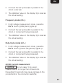
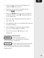
Changing the measurement range
By default, the measurement range is set
automatically and the Auto Range indicator (7)
lights up. It is possible to set the measurement
range manually.
• Press the RANGE button (C) to activate the
manual mode and to disable the automatic range
setting. The Auto Range indicator (7) goes off.
• By every press on the RANGE button (C) the
relevant decimal place changes its position.
• If a reading is higher than the measurement
range, OL lights up on the display (A).
• Press and hold the RANGE button (C) for more
than 1second to exit manual mode and restore
automatic range setting. The Auto Range
indicator(7) lights up.
Relative measurement
The relative measurement feature allows you to
make measurements relative to a stored reference
value.
• Initially, keep the test probes attached to the
circuit or the component to be measured.
• Press the REL button (H) to save this
measurement as the stored reference value and
to zero the display. The indicator (9) lights up.

17
EN
• Press the REL button (H) again to return to
normal operation mode. The indicator (9)
goes off.
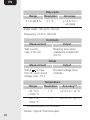
NOTICE
This feature is not applicable for
functions:
Position Function / Measurement
Resistance / diode test / continuity /
capacitance
Frequency / duty cycle
Temperature
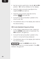
Maximum/minimum measurement
• Press the MAX/MIN button (B) to switch
between the maximum (MAX), minimum (MIN)
and maximum to minimum (MAX-MIN) range
value. The appropriate MAX-MIN indicator (8)
lights up.
• Press the MAX/MIN button (B) for 2seconds
to return to normal operation. The MAX-MIN
indicator (8) goes off.

18
EN
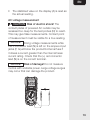
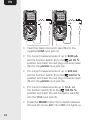
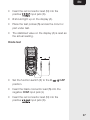
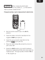
DC voltage measurement
NOTICE
Doing voltage measurements while
the + connector lead (N) is left on the ampere input
jacks (F,G) will blow the product’s internal fuse if
it draws a current greater than the internal fuses
current rating. Check that the (+) red connector
lead (N) is on the correct terminal.
NOTICE
Risk of damage! Do not measure
motors with unstable power. Large voltage surges
may occur that can damage the product.
• Set the function switch (E) to the V position.
• Insert the black connector lead (N) into the
negative COM input jack (L).
• Insert the red connector lead (N) into the
positive input jack (K).
• Connect the test probes (N) in parallel to the
circuit under test.

19
EN
• The stabilized value on the display (A) is read as
the actual reading.
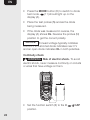
AC voltage measurement
CAUTION
Risk of electric shock! The
contact plates of powered AC outlets may be
recessed too deep for the test probes (N) to reach.
This may give false measurements. Contact point
of measurement must be visible for a true reading.
NOTICE
Doing voltage measurements while
the + connector lead (N) is left on the ampere input
jacks (F, G) will blow the product’s internal fuse if
it draws a current greater than the internal fuses
current rating. Check that the (+) red connector
lead (N) is on the correct terminal.
NOTICE
Risk of damage! Do not measure
motors with unstable power. Large voltage surges
may occur that can damage the product.

20
EN
• Set the function switch (E) to the V~ Hz % VFD
position. “AC” will be indicated on the display.
• Insert the black connector lead (N) into the
negative COM input jack (L).
• Insert the red connector lead (N) into the
positive input jack (K).
• Connect the test probes (N) in parallel to the
circuit under test.
• The stabilized value on the display (A) is read as
the actual reading.
VFD mode (Variable-Frequency Drive)
• In AC voltage measurement mode, press and
hold the MODE button (D) for 2seconds. The
VFD indicator (15) lights up.
• Connect the test probes (N) in parallel to the
circuit or component being measured.
• The stabilized value on the display (A) is read as
the actual reading.
NOTICE
Press the MODE button (D) for
2seconds to return to normal operation. The VFD
indicator(15) goes off.
Page is loading ...
Page is loading ...
Page is loading ...
Page is loading ...
Page is loading ...
Page is loading ...
Page is loading ...
Page is loading ...
Page is loading ...
Page is loading ...
Page is loading ...
Page is loading ...
Page is loading ...
Page is loading ...
Page is loading ...
Page is loading ...
Page is loading ...
Page is loading ...
Page is loading ...
Page is loading ...
Page is loading ...
Page is loading ...
Page is loading ...
Page is loading ...
-
 1
1
-
 2
2
-
 3
3
-
 4
4
-
 5
5
-
 6
6
-
 7
7
-
 8
8
-
 9
9
-
 10
10
-
 11
11
-
 12
12
-
 13
13
-
 14
14
-
 15
15
-
 16
16
-
 17
17
-
 18
18
-
 19
19
-
 20
20
-
 21
21
-
 22
22
-
 23
23
-
 24
24
-
 25
25
-
 26
26
-
 27
27
-
 28
28
-
 29
29
-
 30
30
-
 31
31
-
 32
32
-
 33
33
-
 34
34
-
 35
35
-
 36
36
-
 37
37
-
 38
38
-
 39
39
-
 40
40
-
 41
41
-
 42
42
-
 43
43
-
 44
44


AMAZON COMMERCIAL 6000 Count Compact User manual
- Category
- Multimeters
- Type
- User manual
Ask a question and I''ll find the answer in the document
Finding information in a document is now easier with AI
Related papers

Other documents
-
Extech Instruments MA445 User manual
-
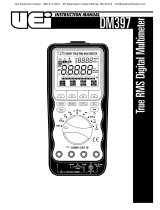 UEi DM397 User manual
-
 UEi DM397 User manual
-
Fluke FLUKE-27II User manual
-
Fluke 1577 Insulation Multimeter User manual
-
Extech Instruments EX650 User manual
-
-
Triplett 9065 User manual
-
Fluke 83V Industrial Multimeter User manual
-

