
85464849176000 REFERENCE NO. SM830076
1
2
3
4
Section
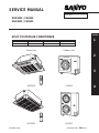
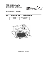
SPLIT SYSTEM AIR CONDITIONER
SERVICE MANUAL
FILE NO.
XHS2432 / CH2432
XHS3632 / CH3632
INDOOR MODEL No. PRODUCT CODE No. OUTDOOR MODEL No. PRODUCT CODE No.
XHS2432 854 013 40 CH2432 854 013 42
XHS3632 854 015 45 CH3632 854 014 57
Indoor Unit Outdoor Unit
XHS3632 CH3632
XHS2432 CH2432

Please Read Before Starting
This air conditioning system meets strict safety and operating
standards. As the installer or service person, it is an important
part of your job to install or service the system so it operates
safely and efficiently.
For safe installation and trouble-free operation, you must :
ⓦ Carefully read this instruction booklet before beginning.
ⓦ Follow each installation or repair step exactly as shown.
ⓦ Observe all local, state, and national electrical codes.
ⓦ Pay close attention to all warning and caution notices
given in this manual.
This symbol refers to a hazard or
unsafe practice which can result in
severe personal injury or death.
This symbol refers to a hazard or
unsafe practice which can result in
personal injury or product or
property damage.
If Necessary, Get Help
These instructions are all you need for most installation sites
and maintenance conditions. If you require help for a special
problem, contact our sales/service outlet or your certified dealer
for additional instructions.
In Case of Improper Installation
The manufacturer shall in no way be responsible for improper
installation or maintenance service, including failure to follow
the instructions in this document.
SPECIAL PRECAUTIONS
When Wiring
……………………………………………………………………
ELECTRICAL SHOCK CAN CAUSE SEVERE
PERSONAL INJURY OR DEATH. ONLY A
QUALIFIED, EXPERIENCED ELECTRICIAN
SHOULD ATTEMPT TO WIRE THIS SYSTEM.
• Do not supply power to the unit until all wiring and tubing are
completed or reconnected and checked.
• Highly dangerous electrical voltages are used in this system.
Carefully refer to the wiring diagram and these instructions
when wiring. Improper connections and inadequate ground-
ing can cause accidental injury or death.
• Ground the unit following local electrical codes.
• Connect all wiring tightly. Loose wiring may cause overheat-
ing at connection points and a possible fire hazard.
When Transporting
……………………………………………………………………
Be careful when picking up and moving the indoor and outdoor
units. Get a partner to help, and bend your knees when lifting to
reduce strain on your back. Sharp edges or thin aluminum fins
on the air conditioner can cut your fingers.
Important
CAUTION
When Installing
……………………………………………………………………
…In a Room
Properly insulate any tubing run inside a room to prevent
“sweating” that can cause dripping and water damage to walls
and floors.
…In Moist or Uneven Locations
Use a raised concrete pad or concrete blocks to provide a
solid, level foundation for the outdoor unit. This prevents water
damage and abnormal vibration.
…In an area with High Winds
Securely anchor the outdoor unit down with bolts and a metal
frame. Provide a suitable air baffle.
…In a Snowy Area (for Heat Pump-type Sys-tems)
Install the outdoor unit on a raised platform that is higher than
drifting snow. Provide snow vents.
When Connecting Refrigerant Tubing
……………………………………………………………………
• Ventilate the room well, in the event that refrigerant gas
leaks during the installation. Be careful not to allow contact
of the refrigerant gas with a flame as this will cause the
generation of poisonous gas.
• Keep all tubing runs as short as possible.
• Use the flare method for connecting tubing.
• Apply refrigerant lubricant to the matching surfaces of the
flare and union tubes before connecting them, then tighten
the nut with a torque wrench for a leak-free connection.
• Check carefully for leaks before starting the test run.
NOTE
Depending on the system type, liquid and gas lines may be
either narrow or wide. Therefore, to avoid confusion the
refrigerant tubing for your particular model is specified as either
“narrow” or “wide” rather than as “liquid” or “gas”.
When Servicing
……………………………………………………………………
• Turn the power OFF at the main power box (mains) before
opening the unit to check or repair electrical parts and
wiring.
• Keep your fingers and clothing away from any moving parts.
• Clean up the site when installation is finished. Check that no
metal scraps or bits of wiring have been left inside the unit.
CAUTION
• Ventilate any enclosed areas when installing or testing the
refrigeration system. Contact of refrigerant gas with fire or
heat can produce poisonous gas.
• Confirm after installation that no refrigerant gas is leaking. If
the gas comes in contact with a burning stove, gas water
heater, electric room heater or other heat source, it can
cause the generation of poisonous gas.
SM830076
– 2 –

– 3 –
SM830076
WHO SHOULD USE THIS MANUAL
This service manual is made to assist the service technician apply his knowledge and training
to this model air conditioner. This manual is written both for experienced service persons
and those who are new to air conditioning service. To help those with less experience or
who are new to this kind of unit we have included more explanations of basic procedures in
simple language than is usual in some service manuals. The experienced technician will of
course find he knows many of these things already and can go directly to the procedures and
information he needs; the less experienced technician will better understand what to do even
before he arrives on the job, and therefore be better able to work by himself as well as assist
the more experienced technician.
TABLE OF CONTENTS
1. SPECIFICATIONS.........................................................................................................6
1-1 Unit Specifications ................................................................................................7
1-2 Major Component Specifications ........................................................................11
(A)Indoor Unit .....................................................................................................11
(B)Outdoor Unit ..................................................................................................13
1-3 Other Component Specifications ........................................................................15
(A)Indoor Unit .....................................................................................................15
(B)Outdoor Unit ..................................................................................................17
1-4 Dimensional Data................................................................................................19
(A)Indoor Unit .....................................................................................................19
(B)Outdoor Unit ..................................................................................................21
1-5 Refrigerant Flow Diagram ...................................................................................23
1-6 Operating Range.................................................................................................23
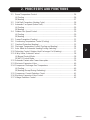
2. PROCESSES AND FUNCTIONS ................................................................................25
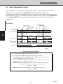
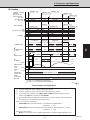
2-1 Room Temperature Control ................................................................................26
(A)Cooling ..........................................................................................................26
(B)Heating ..........................................................................................................27
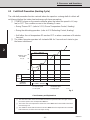
2-2 Cold Draft Prevention (Heating Cycle) ................................................................28
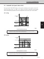
2-3 Automatic Fan Speed (Indoor Unit).....................................................................29
(A)Cooling ..........................................................................................................29
(B)Heating ..........................................................................................................29
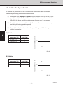
2-4 Outdoor Fan Speed Control................................................................................30
(A)Cooling ..........................................................................................................30
(B)Heating ..........................................................................................................30
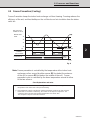
2-5 Freeze Prevention (Cooling) ...............................................................................31
2-6 Condensing Temperature Control (Cooling) ...................................................... 32
2-7 Overload Protection (Heating).............................................................................33
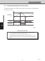
2-8 Discharge Temperature Control (Cooling and Heating)..................................... 34

– 4 –
SM830076
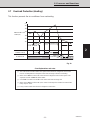
2-9 Auto. Mode for Automatic Heating/Cooling Switching........................................ 35
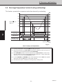
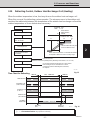
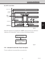
2-10 Defrosting Control, Outdoor Heat Exchanger Coil (Heating).............................. 37
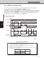
2-11 4-Way Valve, Solenoid Control ...........................................................................38
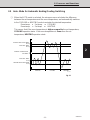
(A)Normal Control Mode ....................................................................................38
(B)AUTO Control Mode ......................................................................................39
2-12 Automatic Restart after Power Interruption........................................................ 39
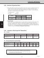
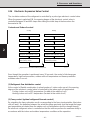
2-13 Electronic Expansion Valve ................................................................................40
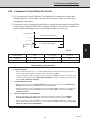
2-14 Compressor Discharge Gas Temperature ......................................................... 40
(A)Cooling ..........................................................................................................40
(B)Heating (Except During Defrosting)...............................................................40
2-15 Compressor Current Detection Circuit ................................................................41
2-16 Electronic Expansion Valve Control....................................................................42
2-17 Voltage Detection Control ...................................................................................43
3. ELECTRICAL DATA....................................................................................................45
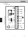
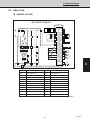
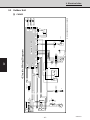
3-1 Indoor Unit (Electric Wiring Diagram, Schematic Diagram) ............................... 46
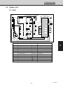
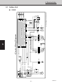
3-2 Outdoor Unit (Electric Wiring Diagram, Schematic Diagram)............................. 48
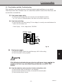
4. SERVICE PROCEDURES ...........................................................................................53
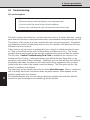
4-1 Troubleshooting ..................................................................................................54
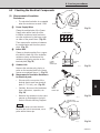
4-2 Checking the Electrical Components ..................................................................87

– 5 –
SM830076
WHAT IS IN THIS MANUAL
Introduction:
Read Me First!
This manual will help you understand and service the air conditioner. To help you find the information you need,
we have divided it into 5 main sections. Each section is divided into chapters with charts, tables and explana-
tions to help you find and repair problems.
❑ Section 1: Specifications, tells you about the physical and electrical make up of the unit, as well
as its heating and cooling capacities. Look in this section to find the correct values for
components and functions.
❑ Section 2: Processes and Functions, explains each different part of the cooling and heating
cycle, and how each control function reacts to changing conditions to keep the room at the set
temperature range.
❑ Section 3: Electrical Data, which has fold-out schematic and wiring diagrams so you can find
the parts you need to check when something is wrong, and see how they should be connected.
❑ Section 4: Service Procedures, has two main parts, a
diagnostic
chapter to help you find the
specific component to replace or adjust, and a chapter with specific procedures and values to
guide you in checking the electrical components in the unit.
HOW TO USE THIS MANUAL
You can use this manual both as a reference
to find specific information about the
capacity, functions and
construction of this unit, and as a source of information to help you set up and maintain the unit.
When this unit is not working properly, and the cause is not known, you can use the procedures in
Section 3: Servicing Procedures to find the problem, fix it, and restore the unit to its proper functioning.
This air conditioner has many helpful self diagnostic features to help you identify problem areas quickly.
So you will be ready when a problem happens, we suggest you look this manual over and become familiar with it
by following these steps:
1. Look at the TABLE OF CONTENTS to get an idea of what is in this manual and where to find it.
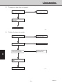
2. Look at the chapter about TROUBLE SHOOTING, so you are familiar with the way the flow
charts work. They are designed to guide you quickly through the possible causes for each kind of
problem that is likely to happen to the Unit. Particularly read the introduction to this section, and
the parts about the self-diagnosis and error codes which show on the display.
3. Look at the chapter about CHECKING ELECTRICAL COMPONENTS. You already know
about most of these procedures. This chapter gives you the specific values and methods for
these components. If you don’t know some of these procedures, you can easily learn them here.
4. Read the Instruction Manual! The Instruction Manual is included here because it helps you help
the user to set the temperature controls properly and know how to take care of any simple
problems that may happen, as well as know when to call for service. The Instruction Manual also
has illustrations, care, and installation information not found in the rest of the service manual. It is
short, and if you read it carefully, you will be able to answer the customers questions easily, and
also know the most efficient ways for setting times and temperatures.
Please use this manual to make your work easier, keep the air conditioner functioning well, and keep your
customers satisfied.

– 6 –
SM830076
1
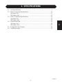
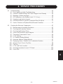
1. SPECIFICATIONS
1-1 Unit Specifications ...........................................................................................7
1-2 Major Component Specifications .................................................................. 11
(A)Indoor Unit ................................................................................................11
(B)Outdoor Unit .............................................................................................13
1-3 Other Component Specifications .................................................................. 15
(A)Indoor Unit ................................................................................................15
(B)Outdoor Unit .............................................................................................17
1-4 Dimensional Data...........................................................................................19
(A)Indoor Unit ................................................................................................19
(B)Outdoor Unit .............................................................................................21
1-5 Refrigerant Flow Diagram ............................................................................. 23
1-6 Operating Range............................................................................................23

1
2
3
4
– 7 –
SM830076
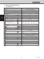
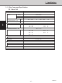
1. Specifications
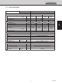
1-1 Unit Specifications
MODEL No. Indoor Unit XHS2432
Outdoor Unit CH2432
POWER SOURCE 230 - 208 V / 1 Phase / 60 Hz
PERFORMANCE Cooling Heating
Capacity* BTU / h 24,000 23,400 25,000 24,300
(17°F)** 16,400 15,800
Moisture removal (High) Pints / h 8.6 8.4 —
Air circulation (Hi)
cu.ft. / min.
540 / 510
S.E.E.R. (H.S.P.F.)
BTU / Wh
10.0 10.2 (7.0) (7.0)
ELECTRICAL RATINGS
Voltage rating VAC 230 208 230 208
Available voltage range VAC 187 - 253 187 - 253
Running amperes A 11.2 11.6 11.7 12.3
Max. running amperes A — — — —
Power input* W 2,450 2,350 2,500 2,450
(17°F)** 2,150 2,020
Buck-up heater kW — — — —
Maximum fuse size A 30
FEATURES
Controls Microprocessor
Fan speeds Indoor / Outdoor 3 and Automatic control / 2 (Auto)
Timer ON / OFF 24-hours & Program
Air deflection Horizontal / Vertical — / Automatic
Air filter Washable, easy access, long life fiter (2,500 hr)
Operation sound Indoor dB - A 37 / 35 / 31
Hi / Me / Lo Outdoor - Hi dB - A 53
Refrigerant control Electronic Refrigerant Control Valve
REFRIGERANT PIPING
Limit of piping length ft. (m) 165 (50)
Limit of piping length at shipment ft. (m) 100 (30)
Limit of elevation difference ft. (m) Outdoor unit is higher than indoor unit: 165 (50)
between the two units Outdoor unit is lower than indoor unit: 100 (30)
Refrigerant piping Narrow pipe in. (mm) 1 / 4 (6.35)
Flare type Wide pipe in. (mm) 3 / 4 (19.05)

1. Specifications
1
2
3
4
– 8 –
SM830076
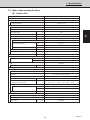
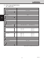
1-1 Unit Specifications
DIMENSIONS & WEIGHT Indoor unit Outdoor unit
Unit dimensions Height in. (mm) 9-27/32 (250) 28-30/32 (735)
Width in. (mm) 29-29/32 (760) 37 (940)
Depth in. (mm) 29-29/32 (760) 13-12/32 (340)
Net weight lbs. (kg) 49 (22) 157 (71)
Indoor grille dimensions Height in. (mm) 3-1/16 (78)
PNR-XHS2432 Width in. (mm) 33-27/32 (860)
Depth in. (mm) 33-27/32 (860)
Net weight lbs. (kg) 11 (5)
Indoor / Outdoor unit Height in. (mm) 11-6/32 (284) 32-17/32 (826)
Package dimensions Width in. (mm) 32-14/32 (824) 40 (1,016)
Depth in. (mm) 32-25/32 (833) 16-12/32 (416)
Shipping weight lbs. (kg) 60 (27) 170 (77)
Shipping volume cu.ft. (m
3
) 6.9 (0.195) 12.3 (0.349)
Indoor grille Height in. (mm) 4-3/32 (104)
Package dimensions Width in. (mm) 38-2/32 (967)
PNR-XHS2432 Depth in. (mm) 39-11/32 (999)
Shipping weight lbs. (kg) 18 (8)
Shipping volume cu.ft. (m
3
) 3.5 (0.100)
DATA SUBJECT TO CHANGE WITHOUT NOTICE
Cooling :
Rating conditions (*) : Room temperature 80 °F DB / 67 °F WB, Ambient temperature 95 °F DB / 75 °F WB
Heating :
Rating conditions (*) : Room temperature 70 °F DB / 60 °F WB, Ambient temperature 47 °F DB / 43 °F WB
Low temp conditions (**): Room temperature 70 °F DB / 60 °F WB, Ambient temperature 17 °F DB / 15 °F WB

1
2
3
4
– 9 –
SM830076
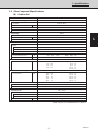
1. Specifications
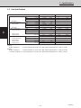
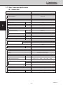
1-1 Unit Specifications
MODEL No. Indoor Unit XHS3632
Outdoor Unit CH3632
POWER SOURCE 230 - 208 VAC / 1 Phase / 60 Hz
PERFORMANCE Cooling Heating
Capacity* BTU / h 34,500 33,500 37,500 36,500
(17°F)** 25,000 23,500
Moisture removal (High) Pints / h 11.1 11.1 —
Air circulation (Hi)
cu.ft. / min.
980 / 880
S.E.E.R. (H.S.P.F.)
BTU / Wh
10.7 11.0 (7.0) (7.0)
ELECTRICAL RATINGS
Voltage rating VAC 230 208 230 208
Available voltage range VAC 187 - 253 187 - 253
Running amperes A 15.4 15.8 18.2 19.3
Max. running amperes A — — — —
Power input* W 3,350 3,200 3,850 3,750
(17°F)** 3,150 2,950
Buck-up heater kW — — — —
Maximum fuse size A 30
FEATURES
Controls Microprocessor
Fan speeds Indoor / Outdoor 3 and Automatic control / 2 (Auto)
Timer ON / OFF 24-hours & Program
Air deflection Horizontal / Vertical — / Automatic
Air filter Washable, easy access, long life fiter (2,500 hr)
Operation sound Indoor dB - A 43 / 40 / 36
Hi / Me / Lo Outdoor - Hi dB - A 56
Refrigerant control Electronic Refrigerant Control Valve
REFRIGERANT PIPING
Limit of piping length ft. (m) 165 (50)
Limit of piping length at shipment ft. (m) 100 (30)
Limit of elevation difference ft. (m) Outdoor unit is higher than indoor unit: 165 (50)
between the two units Outdoor unit is lower than indoor unit: 100 (30)
Refrigerant piping Narrow pipe in. (mm) 3 / 8 (9.52)
Flare type Wide pipe in. (mm) 3 / 4 (19.05)

1. Specifications
1
2
3
4
– 10 –
SM830076
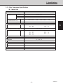
1-1 Unit Specifications
DIMENSIONS & WEIGHT Indoor unit Outdoor unit
Unit dimensions Height in. (mm) 11-1/32 (280) 48-20/32 (1,235)
Width in. (mm) 41-11/32 (1,050) 37 (940)
Depth in. (mm) 29-29/32 (760) 13-12/32 (340)
Net weight lbs. (kg) 60 (27) 203 (92)
Indoor grille dimensions Height in. (mm) 3-1/6 (78)
PNR-XHS3632 Width in. (mm) 33-27/32 (1,150)
Depth in. (mm) 33-27/32 (860)
Net weight lbs. (kg) 15 (7)
Indoor / Outdoor unit Height in. (mm) 12-14/32 (316) 52-7/32 (1,326)
Package dimensions Width in. (mm) 43-27/32 (1,114) 40 (1,016)
Depth in. (mm) 32-25/32 (833) 16-12/32 (416)
Shipping weight lbs. (kg) 71 (32) 227 (103)
Shipping volume cu.ft. (m
3
) 10.3 (0.293) 19.8 (0.56)
Indoor grille Height in. (mm) 4-3/32 (104)
Package dimensions Width in. (mm) 49-16/32 (1,257)
PNR-XHS3632 Depth in. (mm) 39-11/32 (999)
Shipping weight lbs. (kg) 29 (13)
Shipping volume cu.ft. (m
3
) 4.6 (0.131)
DATA SUBJECT TO CHANGE WITHOUT NOTICE
Cooling :
Rating conditions (*) : Room temperature 80 °F DB / 67 °F WB, Ambient temperature 95 °F DB / 75 °F WB
Heating :
Rating conditions (*) : Room temperature 70 °F DB / 60 °F WB, Ambient temperature 47 °F DB / 43 °F WB
Low temp conditions (**): Room temperature 70 °F DB / 60 °F WB, Ambient temperature 17 °F DB / 15 °F WB

1
2
3
4
– 11 –
SM830076
1. Specifications
1-2 Major Component Specifications
(A) Indoor Unit
MODEL No. XHS2432
Source 230 - 208 VAC / 1 phase / 60 Hz
Remote controller (Accessory) RCS - 5HPS4U
Controller P. C. B Ass'y CR - THS2432
Control circuit fuse 250 VAC, 3 A
Controller Ass'y CR - 3XHS
Fan (Number … diameter) in. (mm) Turbo (1…19-9/32 (490))
Fan motor
Model SFG6X - 41A5P
Source 230 - 208 V / 1 phase / 60 Hz
No. of pole … r.p.m. (230 V, High) rpm 6 … 451
Nominal output W 40
Coil resistance Ω BRW - WHT : 114.0 , ORG - YEL : 66.4
(Ambient temperature 68 °F) WHT - VLT : 23.9 , WHT - PNK : 77.4
VLT - ORG : 12.4 , YEL - BLK : 82.1
Safety device
Operating temperature Open °F266± 14.4
Close °F 174.2 ± 27
Run capacitor VAC, µF 440 V , 4 µF
Electronic expansion valve
Coil DKV - MOZS582E0
Coil resistance (at 20°C) Ω ORG - GRY : 46 , YEL - GRY : 46
RED - GRY : 46 , BLK - GRY : 46
Valve body IKV - 24D12
Heat exchanger
Coil Aluminum plate fin / Copper tube
Rows … Fins per inch 2 … 14.9
Face area ft.
2
(m
2
) 3.18 (0.295)
Panel
Model No. PNR - XHS2432
Indicator Lamp Ass'y IND - 3THS
Auto louver motor MT8 - 3C
Auto louver motor … Rated V, W, rpm 240 VAC , 3 W , 3 rpm
Coil resistance (Ambient temperature 77 °F) Ω 16.430 Ω ± 8 %
DATA SUBJECT TO CHANGE WITHOUT NOTICE

1. Specifications
1
2
3
4
– 12 –
SM830076
1-2 Major Component Specifications
(A) Indoor Unit
MODEL No. XHS3632
Source 230 - 208 VAC / 1 phase / 60 Hz
Remote controller (Accessory) RCS - 5HPS4U
Controller P. C. B Ass'y CR - THS2432
Control circuit fuse 250 VAC, 3 A
Controller Ass'y CR - 3XHS
Fan (Number … diameter) in. (mm) Turbo (1…19-9/32 (490))
Fan motor
Model SFG6X - 61A3P
Source 230 - 208 V / 1 phase / 60 Hz
No. of pole … r.p.m. (230 V, High) rpm 6 … 560
Nominal output W 60
Coil resistance Ω BRW - WHT : 71.1 , ORG - YEL : 22.7
(Ambient temperature 68 °F) WHT - VLT : 8.7 , VLT - PNK : 43.2
VLT - ORG : 13.3 , YEL - BLK : 54.32
Safety device
Operating temperature Open °F266± 14.4
Close °F 174.2 ± 27
Run capacitor VAC, µF 440 V , 6 µF
Electronic expansion valve
Coil EKV - MOZS584E0
Coil resistance (at 20°C) Ω ORG - GRY : 46 , YEL - GRY : 46
RED - GRY : 46 , BLK - GRY : 46
Valve body HKV - 30D16
Heat exchanger
Coil Aluminum plate fin / Copper tube
Rows … Fins per inch 2 … 14.9
Face area ft.
2
(m
2
) 5.17 (0.48)
Panel
Model No. PNR - XHS3632
Indicator Lamp Ass'y IND - 3THS
Auto louver motor MT8 - 3C
Auto louver motor … Rated V, W, rpm 240 VAC , 3 W , 3 rpm
Coil resistance (Ambient temperature 77 °F) Ω 16.430 Ω ± 8 %
DATA SUBJECT TO CHANGE WITHOUT NOTICE

1
2
3
4
– 13 –
SM830076
1. Specifications
1-2 Major Component Specifications
(B) Outdoor Unit
MODEL No. CH2432
Source 230 - 208 VAC / 1 phase / 60 Hz
Controller P.C.B. Ass'y CR - CH2432 (Microprocessor)
Control circuit fuse 250 VAC, 3 A
Compressor Rotary (Hermetic)
Model C - 2R160H6T
Source 230 - 208 VAC / 1 phase / 60 Hz
Nominal output W 1,700
Compressor oil cc 800
Coil resistance (Ambient temperature 77 °F) Ω C – R : 0.885 , C – S : 1.773
Safety device Internal type
Overload relay models —
Operating temperature Open °F 297 ± 9
Close °F 198 ± 20
Operating ampere (at 77 °F) A —
Run capacitor VAC, µF 400 VAC, 40 µF
Crank case heater VAC, W 230 VAC, 30 W
Refrigerant amount charged at shipment lbs. (kg) R22 : 6.17 (2.8)
High pressure switch ACB
-
1UB11
Set pressure OFF lb/in
2
(kg/cm
2
) 426.6 (30 )
ON lb/in
2
(kg/cm
2
) 341.3 ± 28.44 (24 ± 2.0)
Fan Propeller
Number...diameter in. (mm) 1 ... 18 - 3/32 (460)
Fan speeds 2 (AUTO)
Fan motor
Model KFC6T - 91D6P
Source 230 - 208 VAC / 1 phase / 60 Hz
No. of pole ..... rpm (230 V, High) 6 ... 879
Nominal output W 110
Coil resistance Ω BRN – WHT : 67.14 , VLT – YEL : 11.42
(Ambient temperature 68 °F) WHT – VLT : 64.85 , YEL – PNK : 10.60
Safety device Internal type
Operating temperature Open °F 248 ± 9
Close °F 171 ± 27
Run capacitor VAC, µF 440 VAC, 4 µF
Heat exchange
Coil Aluminum plate fin / Copper tube
Rows ..... Fins per inch 2 ... 14.1
Face area ft.
2
(m
2
) 6.78 (0.63)
DATA SUBJECT TO CHANGE WITHOUT NOTICE
+ 28.44
+ 7.11
+ 2.0
+ 0.5

1. Specifications
1
2
3
4
– 14 –
SM830076
1-2 Major Component Specifications
(B) Outdoor Unit
MODEL No. CH3632
Source 230 - 208 VAC / 1 phase / 60 Hz
Controller P.C.B. Ass'y CR - CH2432 (Microprocessor)
Control circuit fuse 250 V, 3 A
Compressor Rotary (Hermetic)
Model C - R221H6R
Source 230 - 208 VAC / 1 phase / 60 Hz
Nominal output W 2,200
Compressor oil cc 1,500
Coil resistance (Ambient temperature 77 °F) Ω C – R : 0.549 , C – S : 1.525
Safety device Internal type
Overload relay models —
Operating temperature Open °F 320 ± 9
Close °F 189 ± 20
Operating ampere (at 77 °F) A —
Run capacitor VAC, µF 400 VAC, 40 µF
Crank case heater VAC, W 230 VAC, 30 W
Refrigerant amount charged at shipment lbs. (kg) R22 : 8.82 (4.0)
High pressure switch ACB
-
1UB11
Set pressure OFF lb/in
2
(kg/cm
2
) 426.6 (30 )
ON lb/in
2
(kg/cm
2
) 341.3 ± 28.44 (24 ± 2.0)
Fan Propeller
Number...diameter in. (mm) 2 ... 18 - 3/32 (460)
Fan speeds 2 (AUTO)
Fan motor
Model KFC6T - 91D6P × 2
Source 230 - 208 V / 1 phase / 60 Hz
No. of pole ..... rpm (230 V, High) 6 ... 879
Nominal output W 110 × 2
Coil resistance Ω BRN – WHT : 67.14 , VLT – YEL : 11.42
(Ambient temperature 68 °F) WHT – VLT : 64.85 , YEL – PNK : 10.60
Safety device Internal type
Operating temperature Open °F 248 ± 9
Close °F 171 ± 27
Run capacitor VAC, µF 440 VAC, 4 µF × 2
Heat exchange
Coil Aluminum plate fin / Copper tube
Rows ..... Fins per inch 2 ... 14.1
Face area ft.
2
(m
2
) 11.63 (1.08)
DATA SUBJECT TO CHANGE WITHOUT NOTICE
+ 28.44
+ 7.11
+ 2.0
+ 0.5

1
2
3
4
– 15 –
SM830076
1. Specifications
1-3 Other Component Specifications
(A) Indoor Unit
MODEL No. XHS2432
Power Transformer ATR – II174B
Rated Primary 220 VAC, 60 Hz
Secondary 14.8 VAC 0.55 mA, 14.8 VAC 0.6 mA
Capacity —
Coil resistance
Ω WHT - WHT : 101 , BRN - BRN : 0.42
(Ambient temprature 77 °F)
Thermistor cut off temperature °F277
Thermistor (Coil sensor) : TH2, 3 PBC - 41E - S26
Coil resistance kΩ 14 °F : 23.7 , 41 °F : 12.1
23 °F : 18.8 , 50 °F : 9.7
32 °F : 15.0 , 59 °F : 8.0
Thermistor (Room sensor) : TH1 KTEC - 35 - S6
Coil resistance kΩ 32 °F : 16.5 , 104 °F : 2.7
41 °F : 12.8 , 113 °F : 2.2
50 °F : 10.0 , 122 °F : 1.8
68 °F : 6.3 , 131 °F : 1.5
86 °F : 4.0 ,
Drain pump WP20SL - 21
Rated 230 / 208 VAC, 12.5 W
Float switch FS - 0218 - 102
MAX Rated (Contact rated) 50 W, DC 5V, 0.1 mA
Solenoid control valve or coil
Solenoid control valve IKV - 24D12
Solenoid coil DKV - MOZS582E0
Indicator Lamp Ass'y IND - 3THS
Synchronized Motor MT8 - 3C

1. Specifications
1
2
3
4
– 16 –
SM830076
1-3 Other Component Specifications
(A) Indoor Unit
MODEL No. XHS3632
Power Transformer ATR – II174B
Rated Primary 220 VAC, 60 Hz
Secondary 14.8 VAC 0.55 mA, 14.8 VAC 0.6 mA
Capacity —
Coil resistance
Ω WHT - WHT : 101 , BRN - BRN : 0.42
(Ambient temprature 77 °F)
Thermistor cut off temperature °F277
Thermistor (Coil sensor) : TH2, 3 PBC - 41E - S36
Coil resistance kΩ 14 °F : 23.7 , 41 °F : 12.1
23 °F : 18.8 , 50 °F : 9.7
32 °F : 15.0 , 59 °F : 8.0
Thermistor (Room sensor) : TH1 KTEC - 35 - S6
Coil resistance kΩ 32 °F : 16.5 , 104 °F : 2.7
41 °F : 12.8 , 113 °F : 2.2
50 °F : 10.0 , 122 °F : 1.8
68 °F : 6.3 , 131 °F : 1.5
86 °F : 4.0 ,
Drain pump WP20SL - 21
Rated 230 / 208 VAC, 12.5 W
Float switch FS - 0218 - 103
MAX Rated (Contact rated) 50 W, DC 5V, 0.1 mA
Solenoid control valve or coil
Solenoid control valve HKV - 30D16
Solenoid coil EKV - MOZS728E0
Indicator Lamp Ass'y IND - 3THS
Synchronized Motor MT8 - 3C
DATA SUBJECT TO CHANGE WITHOUT NOTICE

1
2
3
4
– 17 –
SM830076
1. Specifications
1-3 Other Component Specifications
(B) Outdoor Unit
MODEL No. CH2432
Compressor Motor Magnetic Contactor FMCA - 1UL
Coil rated 240 VAC, 60 Hz
Coil resistance (at 77 °F) Ω 580 ± 15 %
Contact rated (Main) 230 VAC, 20 A
Contact rated (Auxiliary) 230 VAC, 3 A
Power Relay HH62S
Coil rated 240 VAC, 60 Hz
Coil resistance (at 77 °F) kΩ 17.2
Contact rated 220 VAC, 5 A
Power Transformer ATR - I65C
Rated
Primary 220 VAC, 60 Hz
Secondary 14 V, 0.4 A
Capacity 5.6 VA
Coil resistance (at 73 °F ) Ω WHT – WHT : 395.5 , BRN – BRN : 2.19
Thermal cut off temperature °F266
Thermistor (Coil sensor) : TH6, 7
PBC - 41E - S4 , PBC - 41E - S26
Coil resistance kΩ 14 °F : 23.7 , 50 °F : 9.7
23 °F : 18.8 , 68 °F : 6.5
32 °F : 15.0 , 86 °F : 4.4
41 °F : 12.1 , 104 °F : 3.1
113 °F : 2.6
Thermistor (Comp. discharge gas sensor) : TH8
PTC - 51H - S1
Coil resistance kΩ 140 °F : 13.8 , 194 °F : 5.1
158 °F : 9.7 , 212 °F : 3.8
167 °F : 8.2 , 230 °F : 2.8
176 °F : 7.0 , 248 °F : 2.2
185 °F : 5.9 , 266 °F : 1.7
Solenoid control valve or coil
Solenoid control valve V 389100
Solenoid coil LB 59005
Thermistor (PTC) TDK – 101YV
Rated
Max. voltage 400 VAC
Max. ampere 11.5 A
Resistance (at 77 °F) Ω 100 %
DATA SUBJECT TO CHANGE WITHOUT NOTICE
+ 30
– 20

1. Specifications
1
2
3
4
– 18 –
SM830076
1-3 Other Component Specifications
(B) Outdoor Unit
MODEL No. CH3632
Compressor Motor Magnetic Contactor FMCA - 1SUL
Coil rated 240 VAC, 60 Hz
Coil resistance (at 68 °F) Ω 588 ± 10 %
Contact rated (Main) 240 VAC, 26 A
Contact rated (Auxiliary) 240 VAC, 3 A
Power Relay HH62S
Coil rated 240 VAC, 60 Hz
Coil resistance (at 77 °F) kΩ 17.2
Contact rated 220 VAC, 5 A
Power Transformer ATR - I65C
Rated
Primary 220 VAC, 60 Hz
Secondary 14 V, 0.4 A
Capacity 5.6 VA
Coil resistance (at 73 °F ) Ω WHT – WHT : 395.5 , BRN – BRN : 2.19
Thermal cut off temperature °F266
Thermistor (Coil sensor) : TH6, 7
PBC - 41E - S4 , PBC - 41E - S36
Coil resistance kΩ 14 °F : 23.7 , 50 °F : 9.7
23 °F : 18.8 , 68 °F : 6.5
32 °F : 15.0 , 86 °F : 4.4
41 °F : 12.1 , 104 °F : 3.1
113 °F : 2.6
Thermistor (Comp. discharge gas sensor) : TH8
PTC - 51H - S1
Coil resistance kΩ 140 °F : 13.8 , 194 °F : 5.1
158 °F : 9.7 , 212 °F : 3.8
167 °F : 8.2 , 230 °F : 2.8
176 °F : 7.0 , 248 °F : 2.2
185 °F : 5.9 , 266 °F : 1.7
Solenoid control valve or coil
Solenoid control valve V 389100
Solenoid coil LB 59005
Thermistor (PTC) TDK – 101YV
Rated
Max. voltage 400 VAC
Max. ampere 11.5 A
Resistance (at 77 °F) Ω 100 %
DATA SUBJECT TO CHANGE WITHOUT NOTICE
+ 30
– 20

1
2
3
4
– 19 –
SM830076
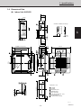
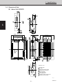
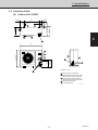
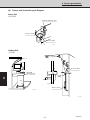
1. Specifications
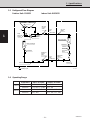
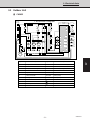
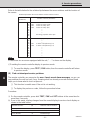
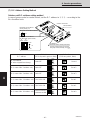
1-4 Dimensional Data
(A) Indoor Unit: XHS2432
33-27/32
3-15/16
29-29/32
19-11/16
19-11/16
11-23/32 1-3/16
8-1/16
6-1/2
1/2
1/2
1-7/8
33-27/32
32-9/32 (Ceiling opening)
32-9/32 (Ceiling opening)
28-3/4(Suspention bolt pitch)
Grille center
23-7/32 (Suspention bolt pitch)
13-2/4 1-3/8
Air intake
Air outlet
Narrow tube (1/4")
Wide tube (3/4")
Drain connection
Power line (conduit size : 1/2")
For discharge duct
Suspention bolt mounting
14
X-view
X
1024_X_S
12
13-3/8
14
5-29/32
10-1/32
7-7/8
Dimension : inch
2-13/32 23/32
6-25/32
• Remote controller (Accessory)
4-29/32
29-29/32
1/2
1/2
3-15/16
8-21/32
8-1/16
19/32
4-29/32
4-29/32
Min. 2-3/8
3-1/32

1. Specifications
1
2
3
4
– 20 –
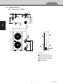
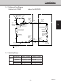
SM830076
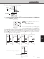
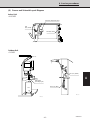
1-4 Dimensional Data
(A) Indoor Unit: XHS3632
45-9/32
41-11/32
31-3/32
19-11/16
12-29/32
1-3/16
8-19/32
4-29/32
33-27/32
43-11/16 (Ceiling opening)
32-9/32 (Ceiling opening)
2-13/32
40-5/32 (Suspention bolt pitch)
Panel center
23-7/32 (Suspention bolt pitch)
19-9/32 1-9/16
Air intake grille
Air outlet
Refrigerant liquid line (ø3/8")
Refrigerant gas line (ø3/4")
Drain connection
Power supply entry
For discharge duct
Humidifier (option) mounting hole
Suspension bolt mounting
X-view
1346_X_S
8-19/32
5-23/321-3/8
8-9/32
2-3/8
29-29/32
2-3/4
6-1/2
11-7/32
8-9/32
3-15/16 3-15/16
9
13-15/32 19/32
15/32
1-7/8
15/32
Dimension : inch
Page is loading ...
Page is loading ...
Page is loading ...
Page is loading ...
Page is loading ...
Page is loading ...
Page is loading ...
Page is loading ...
Page is loading ...
Page is loading ...
Page is loading ...
Page is loading ...
Page is loading ...
Page is loading ...
Page is loading ...
Page is loading ...
Page is loading ...
Page is loading ...
Page is loading ...
Page is loading ...
Page is loading ...
Page is loading ...
Page is loading ...
Page is loading ...
Page is loading ...
Page is loading ...
Page is loading ...
Page is loading ...
Page is loading ...
Page is loading ...
Page is loading ...
Page is loading ...
Page is loading ...
Page is loading ...
Page is loading ...
Page is loading ...
Page is loading ...
Page is loading ...
Page is loading ...
Page is loading ...
Page is loading ...
Page is loading ...
Page is loading ...
Page is loading ...
Page is loading ...
Page is loading ...
Page is loading ...
Page is loading ...
Page is loading ...
Page is loading ...
Page is loading ...
Page is loading ...
Page is loading ...
Page is loading ...
Page is loading ...
Page is loading ...
Page is loading ...
Page is loading ...
Page is loading ...
Page is loading ...
Page is loading ...
Page is loading ...
Page is loading ...
Page is loading ...
Page is loading ...
Page is loading ...
Page is loading ...
Page is loading ...
Page is loading ...
Page is loading ...
Page is loading ...
Page is loading ...
Page is loading ...
Page is loading ...
Page is loading ...
Page is loading ...
Page is loading ...
Page is loading ...
Page is loading ...
Page is loading ...
Page is loading ...
Page is loading ...
Page is loading ...
Page is loading ...
Page is loading ...
Page is loading ...
-
 1
1
-
 2
2
-
 3
3
-
 4
4
-
 5
5
-
 6
6
-
 7
7
-
 8
8
-
 9
9
-
 10
10
-
 11
11
-
 12
12
-
 13
13
-
 14
14
-
 15
15
-
 16
16
-
 17
17
-
 18
18
-
 19
19
-
 20
20
-
 21
21
-
 22
22
-
 23
23
-
 24
24
-
 25
25
-
 26
26
-
 27
27
-
 28
28
-
 29
29
-
 30
30
-
 31
31
-
 32
32
-
 33
33
-
 34
34
-
 35
35
-
 36
36
-
 37
37
-
 38
38
-
 39
39
-
 40
40
-
 41
41
-
 42
42
-
 43
43
-
 44
44
-
 45
45
-
 46
46
-
 47
47
-
 48
48
-
 49
49
-
 50
50
-
 51
51
-
 52
52
-
 53
53
-
 54
54
-
 55
55
-
 56
56
-
 57
57
-
 58
58
-
 59
59
-
 60
60
-
 61
61
-
 62
62
-
 63
63
-
 64
64
-
 65
65
-
 66
66
-
 67
67
-
 68
68
-
 69
69
-
 70
70
-
 71
71
-
 72
72
-
 73
73
-
 74
74
-
 75
75
-
 76
76
-
 77
77
-
 78
78
-
 79
79
-
 80
80
-
 81
81
-
 82
82
-
 83
83
-
 84
84
-
 85
85
-
 86
86
-
 87
87
-
 88
88
-
 89
89
-
 90
90
-
 91
91
-
 92
92
-
 93
93
-
 94
94
-
 95
95
-
 96
96
-
 97
97
-
 98
98
-
 99
99
-
 100
100
-
 101
101
-
 102
102
-
 103
103
-
 104
104
-
 105
105
-
 106
106


Sanyo CH2432 User manual
- Category
- Split-system air conditioners
- Type
- User manual
Ask a question and I''ll find the answer in the document
Finding information in a document is now easier with AI
Related papers
-
Sanyo RCS-KS2432AWD User manual
-
-
-
-
-
-
-
-
Sanyo C1852 User manual
-
Other documents
-
Manitowoc Ice A0100 Product information
-
 Argo Clima AS52AL Datasheet
-
Fujitsu UTY-RNNUM Installation guide
-
Carrier CA27K54 Owner's manual
-
Wisco Industries 621 User guide
-
-
Electrolux EE66WP35PS Product information
-
Premier AA-2118 User manual
-
Amana PALW540RMW1 Datasheet
-
