Sanyo SAP-CMV2441G Technical & Service Manual
- Category
- Split-system air conditioners
- Type
- Technical & Service Manual
This manual is also suitable for

TECHNICAL & SERVICE MANUAL
SAP-KMV91G ´ 3 + SAP-CMV2441G
SAP-KMV181G
or
SAP-KMV91G
´ 4 + SAP-CMV2441G
INVERTER MULTI-SPLIT SYSTEM AIR CONDITIONER
SAP-CMV2441G
SAP-KMV91G ´ 3
FILE NO.
REFERENCE NO. SM700420
W
Indoor Unit Outdoor Unit
SAP-KMV181G
or
SAP-KMV91G ´ 4
Indoor Model No. Product Code No.
SAP-KMV91G-S 1 852 066 82
SAP-KMV181G-S 1 852 066 83
Outdoor Model No. Product Code No.
SAP-CMV2441G 1 852 066 84
Destination: General (50Hz)

i
IMPORTANT!
Please Read Before Starting
This air conditioning system meets strict safety and oper-
ating standards. As the installer or service person, it is an
important part of your job to install or service the system
so it operates safely and efficiently.
For safe installation and trouble-free operation, you
must:
●
Carefully read this instruction booklet before beginning.
●
Follow each installation or repair step exactly as
shown.
●
Observe all local, state, and national electrical codes.
●
Pay close attention to all warning and caution notices
given in this manual.
This symbol refers to a haz-
ard or unsafe practice which
can result in severe personal
injury or death.
This symbol refers to a hazard
or unsafe practice which can
result in personal injury or
product or property damage.
If Necessary, Get Help
These instructions are all you need for most installation
sites and maintenance conditions. If you require help for
a special problem, contact our sales/service outlet or
your certified dealer for additional instructions.
In Case of Improper Installation
The manufacturer shall in no way be responsible for
improper installation or maintenance service, including
failure to follow the instructions in this document.
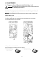
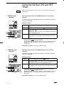
SPECIAL PRECAUTIONS
When Wiring
ELECTRICAL SHOCK CAN CAUSE
SEVERE PERSONAL INJURY OR DEATH.
ONLY A QUALIFIED, EXPERIENCED
ELECTRICIAN SHOULD ATTEMPT TO
WIRE THIS SYSTEM.
• Do not supply power to the unit until all wiring and tub-
ing are completed or reconnected and checked.
• Highly dangerous electrical voltages are used in this
system. Carefully refer to the wiring diagram and
these instructions when wiring. Improper connections
and inadequate grounding can cause accidental
injury or death.
• Ground the unit following local electrical codes.
• Connect all wiring tightly. Loose wiring may cause
overheating at connection points and a possible fire
hazard.
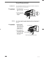
When Transporting
Be careful when picking up and moving the indoor and
outdoor units. Get a partner to help, and bend your
knees when lifting to reduce strain on your back. Sharp
edges or thin aluminum fins on the air conditioner can
cut your fingers.
When Installing…
…In a Ceiling or Wall
Make sure the ceiling/wall is strong enough to hold the
unit’s weight. It may be necessary to construct a strong
wood or metal frame to provide added support.
…In a Room
Properly insulate any tubing run inside a room to prevent
“sweating” that can cause dripping and water damage to
walls and floors.
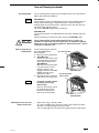
…In Moist or Uneven Locations
Use a raised concrete pad or concrete blocks to provide
a solid, level foundation for the outdoor unit. This pre-
vents water damage and abnormal vibration.
…In an Area with High Winds
Securely anchor the outdoor unit down with bolts and a
metal frame. Provide a suitable air baffle.
…In a Snowy Area (for Heat Pump-type Systems)
Install the outdoor unit on a raised platform that is higher
than drifting snow. Provide snow vents.
When Connecting Refrigerant Tubing
• Use the flare method for connecting tubing.
• Apply refrigerant lubricant to the matching surfaces of
the flare and union tubes before connecting them,
then tighten the nut with a torque wrench for a leak-
free connection.
• Check carefully for leaks before starting the test run.
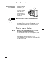
When Servicing
• Turn the power OFF at the main power box (mains)
before opening the unit to check or repair electrical
parts and wiring.
• Keep your fingers and clothing away from any moving
parts.
• Clean up the site after you finish, remembering to
check that no metal scraps or bits of wiring have been
left inside the unit being serviced.
Others
• Ventilate any enclosed areas when installing or testing
the refrigeration system. Escaped refrigerant gas, on
contact with fire or heat, can produce dangerously
toxic gas.
• Confirm upon completing installation that no refriger-
ant gas is leaking. If escaped gas comes in contact
with a stove, gas water heater, electric room heater or
other heat source, it can produce dangerously toxic
gas.
WARNING
WARNING
CAUTION
CAUTION

ii
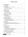
Table of Contents
Page
■
UNIT COMBINATION ................................................................................................................ iii
1. OPERATING RANGE................................................................................................................ 1
2. SPECIFICATIONS
2-1. Specifications in Combination with Indoor Units................................................................ 1
2-2. Unit Specifications ............................................................................................................. 3
2-3. Major Component Specifications....................................................................................... 8
2-4. Other Component Specifications....................................................................................... 9
3. DIMENSIONAL DATA................................................................................................................ 10
4. FREQUENCY CHARTS
4-1. Cooling Capacity................................................................................................................ 13
4-2. Frequency Characteristics .................................................................................................17
5. AIR THROW DISTANCE CHARTS............................................................................................ 18
6. REFRIGERANT FLOW DIAGRAM............................................................................................ 19
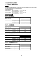
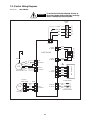
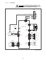
7. ELECTRICAL DATA
7-1. Electrical Characteristics.................................................................................................... 20
7-2. Electric Wiring Diagrams.................................................................................................... 22
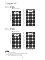
7-3. Performance Charts........................................................................................................... 25
8. INSTALLATION INSTRUCTIONS
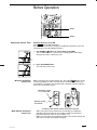
8-1. Installation Site Selection................................................................................................... 26
8-2. Remote Control Unit Installation Position........................................................................... 28
8-3. Recommended Wire Length and Diameter........................................................................ 29
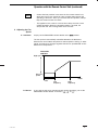
8-4. Setting for Electric Current Suppressor ............................................................................. 30
8-5. Tubing Check Function....................................................................................................... 30
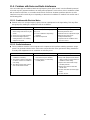
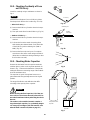
9. MAINTENANCE
9-1. Changing Address of Remote Control Unit in Indoor Unit ................................................. 32
9-2. Disconnecting and Connecting Positive Connector for Outdoor Unit................................. 33
9-3. Replacing Thermistors (on outdoor unit) for Electronic Expansion Valves ........................ 33
10. FUNCTIONS
10-1. Functions for Operation.................................................................................................... 34
10-2. Protective Functions......................................................................................................... 36
11. TROUBLESHOOTING
11-1. Operating State................................................................................................................ 37
11-2. Troubleshooting Using the Self-Diagnostic Monitor ......................................................... 38
11-3. Fault Assessment of Indoor/Outdoor Unit........................................................................ 40
11-4. Checkpoints for Each Component and Check Procedure................................................ 41
11-5. Problems with Noise and Radio Interference................................................................... 44
12. CHECKING ELECTRICAL COMPONENTS
12-1. Measurement of Insulation Resistance............................................................................ 45
12-2. Checking Continuity of Fuse on PCB Ass’y..................................................................... 46
12-3. Checking Motor Capacitor................................................................................................ 46
INSTRUCTION MANUAL.......................................................................................... 47
APPENDIX

iii
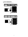
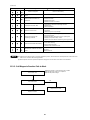
■ UNIT COMBINATION
Combine indoor and outdoor units only as listed below.
Outdoor Unit Indoor Unit Symbol of Indoor Unit Refer to
SAP-CMV2441G
SAP-KMV91G A to C
Fig. 1
SAP-KMV181G D
Outdoor Unit Indoor Unit Symbol of Indoor Unit Refer to
SAP-CMV2441G SAP-KMV91G A to D Fig. 2
D
C
B
A
Fig. 1
D
C
B
A
Fig. 2

1
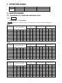
1. OPERATING RANGE
Temperature Indoor Air Intake Temp. Outdoor Air Intake Temp.
Cooling
Maximum 32°C D.B. / 23°C W.B. 43°C D.B.
Minimum 19°C D.B. / 14°C W.B. 19°C D.B.
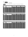
2. SPECIFICATIONS
2-1. Specifications in Combination with Indoor Units
2-1-1.
91: SAP-KMV91G 181: SAP-KMV181G
Refer to “8-4. Setting for Electric Current Suppressor” for switching between FREE/11/8.5A.
■
Free
NOTE
At 220V
Combination
Total cooling capacity
Total power input (W) Total current (A)
Indoor capacity (kW) (kW)
of indoor unit
Min ST Max Min ST Max Min ST Max
91 2.60 — — — 0.80 2.60 2.90 360 1020 1300 2.2 5.8 7.0
181 — — — 5.20 1.00 5.20 5.60 420 2070 2490 2.4 10.5 12.4
91 ´ 2 2.55 2.55 — — 1.20 5.10 5.40 400 2020 2340 2.3 10.3 11.7
91 + 181 2.10 — — 4.40 1.40 6.50 6.90 450 2570 3190 2.5 12.8 15.7
91 ´ 3 2.15 2.15 2.15 — 1.50 6.45 6.90 430 2420 3180 2.4 12.2 15.8
91 ´ 2 + 181 1.70 1.70 — 3.50 2.30 6.90 7.50 610 2370 3270 3.5 11.9 16.2
91 ´ 4 1.75 1.75 1.75 1.75 2.20 7.00 7.60 600 2450 3300 3.4 12.3 16.2
91 ´ 3 + 181 1.45 1.45 1.45 2.85 3.30 7.20 8.00 870 2310 3390 5.1 11.6 16.8
■
11A
Combination
Total cooling capacity
Total power input (W) Total current (A)
Indoor capacity (kW) (kW)
of indoor unit
Min ST Max Min ST Max Min ST Max
91 2.60 — — — 0.80 2.60 2.90 360 1020 1300 2.2 5.8 7.0
181 — — — 5.20 1.00 5.20 5.30 420 2070 2200 2.4 10.5 11.0
91 ´ 2 2.55 2.55 — — 1.20 5.10 5.20 400 2020 2150 2.3 10.3 11.0
91+181 1.90 — — 4.00 1.40 5.90 5.90 450 2210 2210 2.5 11.0 11.0
91 ´ 3 1.95 1.95 1.95 — 1.50 5.85 5.85 430 2200 2200 2.4 11.0 11.0
91 ´ 2 + 181 1.60 1.60 — 3.30 2.30 6.50 6.50 610 2220 2220 3.5 11.0 11.0
91 ´ 4 1.60 1.60 1.60 1.60 2.20 6.40 6.40 600 2220 2220 3.4 11.0 11.0
91 ´ 3 + 181 1.30 1.30 1.30 2.60 3.30 6.50 6.50 870 2170 2170 5.1 11.0 11.0
■
8.5A
Combination
Total cooling capacity
Total power input (W) Total current (A)
Indoor capacity (kW) (kW)
of indoor unit
Min ST Max Min ST Max Min ST Max
91 2.60 — — — 0.80 2.60 2.90 360 1020 1300 2.2 5.8 7.0
181 — — — 4.40 1.00 4.40 4.40 420 1640 1640 2.4 8.5 8.5
91 ´ 2 2.10 2.10 — — 1.20 4.20 4.20 400 1650 1650 2.3 8.5 8.5
91+181 1.65 — — 3.35 1.40 5.00 5.00 450 1670 1670 2.5 8.5 8.5
91 ´ 3 1.65 1.65 1.65 — 1.50 4.95 4.95 430 1660 1660 2.4 8.5 8.5
91 ´ 2 + 181 1.40 1.40 — 2.75 2.30 5.55 5.55 610 1670 1670 3.5 8.5 8.5
91 ´ 4 1.35 1.35 1.35 1.35 2.20 5.40 5.40 600 1670 1670 3.4 8.5 8.5
91 ´ 3 + 181 1.10 1.10 1.10 2.20 3.30 5.50 5.50 870 1630 1630 5.1 8.5 8.5

2
2-1-2.
91: SAP-KMV91G 181: SAP-CMV2441G
Refer to “8-4. Setting for Electric Current Suppressor” for switching between FREE/11/8.5A.
■
Free
NOTE
At 230V
Combination
Total cooling capacity
Total power input (W) Total current (A)
Indoor capacity (kW) (kW)
of indoor unit
Min ST Max Min ST Max Min ST Max
91 2.60 — — — 0.80 2.60 2.90 380 1070 1360 2.2 5.9 7.1
181 — — — 5.20 1.00 5.20 5.60 430 2120 2550 2.4 10.3 12.2
91 ´ 2 2.55 2.55 — — 1.20 5.10 5.40 410 2080 2410 2.3 10.2 11.6
91 + 181 2.10 — — 4.40 1.40 6.50 6.90 450 2570 3190 2.4 12.4 15.2
91 ´ 3 2.15 2.15 2.15 — 1.50 6.45 6.90 430 2430 3190 2.3 11.7 15.2
91 ´ 2 + 181 1.70 1.70 — 3.50 2.30 6.90 7.50 620 2400 3310 3.4 11.6 15.8
91 ´ 4 1.75 1.75 1.75 1.75 2.20 7.00 7.60 600 2450 3300 3.3 11.9 15.7
91 ´ 3 + 181 1.45 1.45 1.45 2.85 3.30 7.20 8.00 890 2360 3460 5.0 11.4 16.5
■
11A
Combination
Total cooling capacity
Total power input (W) Total current (A)
Indoor capacity (kW) (kW)
of indoor unit
Min ST Max Min ST Max Min ST Max
91 2.60 — — — 0.80 2.60 2.90 380 1070 1360 2.2 5.9 7.1
181 — — — 5.20 1.00 5.20 5.30 430 2120 2250 2.4 10.3 11.0
91 ´ 2 2.55 2.55 — — 1.20 5.10 5.20 410 2080 2200 2.3 10.2 11.0
91 + 181 1.90 — — 4.00 1.40 5.90 5.90 450 2210 2210 2.4 11.0 11.0
91 ´ 3 1.95 1.95 1.95 — 1.50 5.85 5.85 430 2210 2210 2.3 11.0 11.0
91 ´ 2 + 181 1.60 1.60 — 3.30 2.30 6.50 6.50 620 2250 2250 3.4 11.0 11.0
91 ´ 4 1.60 1.60 1.60 1.60 2.20 6.40 6.40 600 2220 2220 3.3 11.0 11.0
91 ´ 3 + 181 1.30 1.30 1.30 2.60 3.30 6.50 6.50 890 2210 2210 5.0 11.0 11.0
■
8.5A
Combination
Total cooling capacity
Total power input (W) Total current (A)
Indoor capacity (kW) (kW)
of indoor unit
Min ST Max Min ST Max Min ST Max
91 2.60 — — — 0.80 2.60 2.90 380 1070 1360 2.2 5.9 7.1
181 — — — 4.40 1.00 4.40 4.40 430 1680 1680 2.4 8.5 8.5
91 ´ 2 2.10 2.10 — — 1.20 4.20 4.20 410 1700 1700 2.3 8.5 8.5
91 + 181 1.65 — — 3.35 1.40 5.00 5.00 450 1670 1670 2.4 8.5 8.5
91 ´ 3 1.65 1.65 1.65 — 1.50 4.95 4.95 430 1670 1670 2.3 8.5 8.5
91 ´ 2 + 181 1.40 1.40 — 2.75 2.30 5.55 5.55 620 1690 1690 3.4 8.5 8.5
91 ´ 4 1.35 1.35 1.35 1.35 2.20 5.40 5.40 600 1670 1670 3.3 8.5 8.5
91 ´ 3 + 181 1.10 1.10 1.10 2.20 3.30 5.50 5.50 890 1660 1660 5.0 8.5 8.5

3
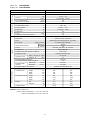
2-2. Unit Specifications
The following are the specifications with the electric current suppressor set to “FREE.” (Please refer to 8-4 for
details)
Indoor unit SAP-KMV91G
Outdoor unit SAP-CMV2441G
NOTE
No. of Indoor Units 1-unit type
Power Source 220 – 230V ~ 50Hz
Cooling
Capacity
kW 2.6 (0.8 – 2.9)
BTU/h 8,900 (2,700 – 9,900)
Air circulation (High) m
3
/h 430
Moisture removal (High) Liters/h 1.3
Voltage rating V 230
Available voltage range V 198 – 253
Running amperes A 5.9 (2.2 – 7.1)
Power input W 1,070 (380 – 1,360)
Power factor % 79
C.O.P. W/W 2.4
Compressor locked rotor amperes A 23
Controls / Temperature control Microprocessor / I.C. thermostat
Control unit Wireless remote control unit
Timer ON/OFF 24-hours & Daily program, 1-hour OFF
Fan speeds Indoor / Outdoor 3 and Auto / Auto (Variable)
Airflow direction (Indoor)
Horizontal Manual
Vertical Auto
Air filter Washable, Anti-mold
Compressor Rotary (Hermetic)
Refrigerant / Amount charged at shipment g R22 / 2,500
Refrigerant control Electrical expansion valve
Operation sound
Indoor – Hi / Me / Lo dB-A 39 / 35 / 31
Outdoor – Hi dB-A 47
Refrigerant tubing connections Flare type
Max. allowable tubing length at shipment m 20
Refrigerant tube
Narrow tube mm (in.) 6.35 (1/4)
diameter
Wide tube mm (in.) 12.7 (1/2)
Refrigerant tube kit / Accessories Optional / Hanging wall bracket
Indoor unit Outdoor unit
Unit dimensions Height mm 250 625
Width mm 790 880
Depth mm 174 295
Package dimensions Height mm 242 699
Width mm 850 1,126
Depth mm 312 401
Weight Net kg 7.0 63.0
Shipping kg 10.0 68.0
Shipping volume m
3
0.063 0.316
PerformanceElectrical RatingFeatures
Dimensions & Weight
DATA SUBJECT TO CHANGE WITHOUT NOTICE.
Remarks: Rating conditions are:
Cooling: Indoor air temperature 27°C D.B. / 19°C W.B.
Outdoor air temperature 35°C D.B. / 24°C W.B.

4
Indoor unit SAP-KMV181G
Outdoor unit SAP-CMV2441G
No. of Indoor Units 1-unit type
Power Source 220 – 230V ~ 50Hz
Cooling
Capacity
kW 5.2 (1.0 – 5.6)
BTU/h 17,700 (3,400 – 19,100)
Air circulation (High) m
3
/h 780
Moisture removal (High) Liters/h 2.7
Voltage rating V 230
Available voltage range V 198 – 253
Running amperes A 10.3 (2.4 – 12.2)
Power input W 2,120 (430 – 2,550)
Power factor % 90
C.O.P. W/W 2.5
Compressor locked rotor amperes A 23
Controls / Temperature control Microprocessor / I.C. thermostat
Control unit Wireless remote control unit
Timer ON/OFF 24-hours & Daily program, 1-hour OFF
Fan speeds Indoor / Outdoor 3 and Auto / Auto (Variable)
Airflow direction (Indoor)
Horizontal Manual
Vertical Auto
Air filter Washable, Anti-mold + Air clean filter
Compressor Rotary (Hermetic)
Refrigerant / Amount charged at shipment g R22 / 2,500
Refrigerant control Electrical expansion valve
Operation sound
Indoor – Hi / Me / Lo dB-A 41 / 39 / 36
Outdoor – Hi dB-A 47
Refrigerant tubing connections Flare type
Max. allowable tubing length at shipment m 20
Refrigerant tube
Narrow tube mm (in.) 6.35 (1/4)
diameter
Wide tube mm (in.) 9.52 (3/8)
Refrigerant tube kit / Accessories Optional / Hanging wall bracket
Indoor unit Outdoor unit
Unit dimensions Height mm 285 625
Width mm 995 880
Depth mm 196 295
Package dimensions Height mm 363 699
Width mm 1,070 1,126
Depth mm 276 401
Weight Net kg 12.0 63.0
Shipping kg 15.0 68.0
Shipping volume m
3
0.108 0.316
PerformanceElectrical RatingFeatures
Dimensions & Weight
DATA SUBJECT TO CHANGE WITHOUT NOTICE.
Remarks: Rating conditions are:
Cooling: Indoor air temperature 27°C D.B. / 19°C W.B.
Outdoor air temperature 35°C D.B. / 24°C W.B.

5
Indoor unit SAP-KMV91G + KMV181G
Outdoor unit SAP-CMV2441G
No. of Indoor Units 2-unit type
Power Source 220 – 230V ~ 50Hz
Cooling
Capacity
kW 6.5 (1.4 – 6.9)
BTU/h 22,200 (4,800 – 23,500)
Air circulation (High) m
3
/h 1.210
Moisture removal (High) Liters/h 4.0
Voltage rating V 230
Available voltage range V 198 – 253
Running amperes A 12.4 (2.4 – 15.2)
Power input W 2,570 (450 – 3,190)
Power factor % 90
C.O.P. W/W 2.5
Compressor locked rotor amperes A —
PerformanceElectrical Rating
DATA SUBJECT TO CHANGE WITHOUT NOTICE.
Remarks: Rating conditions are:
Cooling: Indoor air temperature 27°C D.B. / 19°C W.B.
Outdoor air temperature 35°C D.B. / 24°C W.B.
Indoor unit SAP-KMV91G ´ 2
Outdoor unit SAP-CMV2441G
No. of Indoor Units 2-unit type
Power Source 220 – 230V ~ 50Hz
Cooling
Capacity
kW 5.1 (1.2 – 5.4)
BTU/h 17,400 (4,090 – 18,400)
Air circulation (High) m
3
/h 860
Moisture removal (High) Liters/h 2.6
Voltage rating V 230
Available voltage range V 198 – 253
Running amperes A 10.2 (2.3 – 11.6)
Power input W 2,080 (410 – 2,410)
Power factor % 89
C.O.P. W/W 2.5
Compressor locked rotor amperes A —
PerformanceElectrical Rating
DATA SUBJECT TO CHANGE WITHOUT NOTICE.
Remarks: Rating conditions are:
Cooling: Indoor air temperature 27°C D.B. / 19°C W.B.
Outdoor air temperature 35°C D.B. / 24°C W.B.

6
Indoor unit SAP-KMV91G ´ 3
Outdoor unit SAP-CMV2441G
No. of Indoor Units 3-unit type
Power Source 220 – 230V ~ 50Hz
Cooling
Capacity
kW 6.45 (1.5 – 6.9)
BTU/h 22,000 (5,100 – 23,500)
Air circulation (High) m
3
/h 1,290
Moisture removal (High) Liters/h 3.9
Voltage rating V 230
Available voltage range V 198 – 253
Running amperes A 11.7 (2.3 – 15.2)
Power input W 2,430 (430 – 3,190)
Power factor % 90
C.O.P. W/W 2.7
Compressor locked rotor amperes A —
PerformanceElectrical Rating
DATA SUBJECT TO CHANGE WITHOUT NOTICE.
Remarks: Rating conditions are:
Cooling: Indoor air temperature 27°C D.B. / 19°C W.B.
Outdoor air temperature 35°C D.B. / 24°C W.B.
Indoor unit SAP-KMV91G ´ 2 + KMV181G
Outdoor unit SAP-CMV2441G
No. of Indoor Units 3-unit type
Power Source 220 – 230V ~ 50Hz
Cooling
Capacity
kW 6.9 (2.3 – 7.5)
BTU/h 23,500 (7,800 – 25,600)
Air circulation (High) m
3
/h 1,640
Moisture removal (High) Liters/h 5.3
Voltage rating V 230
Available voltage range V 198 – 253
Running amperes A 11.6 (3.4 – 15.8)
Power input W 2,400 (620 – 3,310)
Power factor % 90
C.O.P. W/W 2.9
Compressor locked rotor amperes A —
PerformanceElectrical Rating
DATA SUBJECT TO CHANGE WITHOUT NOTICE.
Remarks: Rating conditions are:
Cooling: Indoor air temperature 27°C D.B. / 19°C W.B.
Outdoor air temperature 35°C D.B. / 24°C W.B.

7
Indoor unit SAP-KMV91G ´ 4
Outdoor unit SAP-CMV2441G
No. of Indoor Units 4-unit type
Power Source 220 – 230V ~ 50Hz
Cooling
Capacity
kW 7.0 (2.2 – 7.6)
BTU/h 23,900 (7,500 – 25,900)
Air circulation (High) m
3
/h 1,720
Moisture removal (High) Liters/h 5.2
Voltage rating V 230
Available voltage range V 198 – 253
Running amperes A 11.9 (3.3 – 15.7)
Power input W 2,450 (600 – 3,300)
Power factor % 90
C.O.P. W/W 2.9
Compressor locked rotor amperes A
—
PerformanceElectrical Rating
DATA SUBJECT TO CHANGE WITHOUT NOTICE.
Remarks: Rating conditions are:
Cooling: Indoor air temperature 27°C D.B. / 19°C W.B.
Outdoor air temperature 35°C D.B. / 24°C W.B.
Indoor unit SAP-KMV91G ´ 3 + KMV181G
Outdoor unit SAP-CMV2441G
No. of Indoor Units 4-unit type
Power Source 220 – 230V ~ 50Hz
Cooling
Capacity
kW 7.2 (3.3 – 8.0)
BTU/h 24,600 (11,300 – 27,300)
Air circulation (High) m
3
/h 2,070
Moisture removal (High) Liters/h 6.6
Voltage rating V 230
Available voltage range V 198 – 253
Running amperes A 11.4 (5.0 – 16.5)
Power input W 2,360 (890 – 3,460)
Power factor % 90
C.O.P. W/W 3.1
Compressor locked rotor amperes A —
PerformanceElectrical Rating
DATA SUBJECT TO CHANGE WITHOUT NOTICE.
Remarks: Rating conditions are:
Cooling: Indoor air temperature 27°C D.B. / 19°C W.B.
Outdoor air temperature 35°C D.B. / 24°C W.B.

8
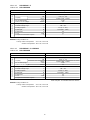
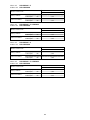
2-3. Major Component Specifications
Indoor unit SAP-KMV91G
Part No. POW-KMV91G
Controls Microprocessor
Control circuit fuse 250V – 3.15A
Remote Control Unit RCS-1MPS4E
Type Cross-flow
Q’ty … Dia. and Length mm 1 … ø95 / L617
Fan motor model … Q’ty UF4-21B5PA-S … 1
No. of poles … rpm (230V, High) 4 … 1,350
Nominal output W 20
Coil resistance ½ BRN – WHT: 402
(Ambient temp. 20°C)
PNK – WHT: 506
Run capacitor
µF —
VAC —
Controller
PCB
Fan & Fan Motor
DATA SUBJECT TO CHANGE WITHOUT NOTICE.
Indoor unit SAP-KMV181G
Part No. POW-KMV181G
Controls Microprocessor
Control circuit fuse 250V – 3.15A
Remote Control Unit RCS-1MPS4E
Type Cross-flow
Q’ty … Dia. and Length mm 1 … ø88 / L617
Fan motor model … Q’ty UF2-31A5P-S … 1
No. of poles … rpm (230V, High) 2 … 1,440
Nominal output W 30
Coil resistance ½ BRN – WHT: 130
(Ambient temp. 20°C)
WHT – PNK: 170
Run capacitor
µF 2.0
VAC 440
Controller
PCB
Fan & Fan Motor
DATA SUBJECT TO CHANGE WITHOUT NOTICE.
Part No. POW-CMV2441G (B)
Control circuit fuse 250V – 3A
Type Rotary (hermetic)
Compressor model … Q’ty C-7RV113H0W … 1 / 80831080
Nominal output W 700
Compressor oil … Amount cc SUNISO 4GSD-T … 600
Coil resistance ½ C – R: 0.684
(Ambient temp. 25°C) C – S: 0.686
Run capacitor µF —
… Q’ty VAC —
Type Propeller
Q’ty … Dia. mm 1 … ø400
Fan motor model … Q’ty KFG6S-41B5P … 1
No. of poles … rpm (230V, High) 6 … 720
Nominal output W 40
½ WHT – BRN: 150
Coil resistance WHT – YEL: 89
YEL – PNK: 166
Run capacitor
µF 2.0
VAC 440
DATA SUBJECT TO CHANGE WITHOUT NOTICE.
CompressorFan & Fan Motor
Controller
PCB
Outdoor unit SAP-CMV2441G

9
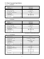
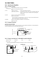
2-4. Other Component Specifications
Indoor unit SAP-KMV91G and SAP-KMV181G
Thermistor (Coil sensor) DTN-TKS150Y
Resistance k½ 25°C 58.3
Thermistor (Room sensor) DTN-TKS150Y
Resistance k½ 25°C 5.0±3%
DATA SUBJECT TO CHANGE WITHOUT NOTICE.
Thermistor (Air sensor) PBC-41E-S14
Resistance k½ 0°C 15
Thermistor (Compressor sensor) PTC-51H-S1
Resistance k½ 50°C 20
Thermistor (Electric exp. valve sensor) PBC-41E-S25
Resistance k½ 0°C 15
PTC Thermistor (TH) 912X24E400XR-A
Resistance ½ (at 25°C) 40
Outdoor unit SAP-CMV2441G
DATA SUBJECT TO CHANGE WITHOUT NOTICE.

10
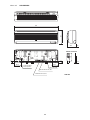
790
250
174 (3)
Narrow tube ø6.35 (1/4")
Wide tube ø9.52 (3/8")
Drain hose ø18
58.5
132
41.0
41.0
Center of tubing
hole (2 places)
Remote control unit
23
61
182
3. DIMENSIONAL DATA
Indoor unit SAP-KMV91G
Unit: mm

11
Indoor unit SAP-KMV181G
28545
995
45
147.5 147.5
196 (3)
Remote control unit
Center of tubing
hole (2 places)
Narrow tube ø6.35 (1/4")
Drain hose ø18
Wide tube ø12.7 (1/2")
23
61
182
Unit: mm

12
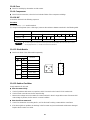
Outdoor unit SAP-CMV2241G
963 963
609
Air discharge
Air intake
Air intake
136 35
625
30072.5
334
310
16
125
8
➀ Narrow tube service valve
4-ø6.35 (1/4")
➁ Wide tube service valve
3-ø9.52 (3/8")
➂ Wide tube service valve
1-ø12.7 (1/2")
➀
➁
➂
83.0
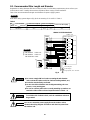
Service valve
narrow tube
Service valve
wide tube
Service valve
narrow tube
Service valve
wide tube
1/4" (ø6.35)
3/8" (ø9.52)
Unit A
1/4" (ø6.35)
3/8" (ø9.52)
Unit B
1/4" (ø6.35)
3/8" (ø9.52)
Unit C
1/4" (ø6.35)
1/2" (ø12.7)
Unit D
SAP-KMV91G
SAP-KMV181G or
SAP-KMV91G*
* A tube joint (ø12.7 to 9.52) is needed
when SAP-KMV91G is installed. Please
consult your dealer or installer.
Unit: mm

13
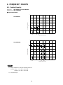
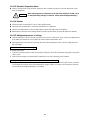
4. FREQUENCY CHARTS
4-1. Cooling Capacity
Indoor unit SAP-KMV91G and SAP-KMV181G
Outdoor unit SAP-CMV2441G
1) Rating conditions in cooling and heating mode are:
Cooling Indoor: 27°C D.B. / 19°C W.B.
Outdoor: 35°C D.B. / 24°C W.B.
2) Fan speed: High
NOTE
0
0 20 40 60 80 100 120 140 160
1
2
3
4
5
6
7
Operating frequency (Hz)
Cooling capacity (kW)
15 5242
2.6
0
0 20 40 60 80 100 120 140 160
1
2
3
4
5
6
7
Operating frequency (Hz)
Cooling capacity (kW)
15 9073
5.2
■
Single-unit operation
SAP-KMV91G
SAP-KMV181G

14
1) Rating conditions in cooling and heating mode are:
Cooling Indoor: 27°C D.B. / 19°C W.B.
Outdoor: 35°C D.B. / 24°C W.B.
2) Fan speed: High
NOTE
■
Two-unit operation
SAP-KMV91G ´ 2
SAP-KMV91G + SAP-KMV181G
0
0 20 40 60 80 100 120 140 160
1
2
3
4
5
6
7
Operating frequency (Hz)
Cooling capacity (kW)
15 8570
5.1
0
0 20 40 60 80 100 120 140 160
1
2
3
4
5
6
7
Operating frequency (Hz)
Cooling capacity (kW)
15 85
6.5

15
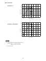
1) Rating conditions in cooling and heating mode are:
Cooling Indoor: 27°C D.B. / 19°C W.B.
Outdoor: 35°C D.B. / 24°C W.B.
2) Fan speed: High
NOTE
■
Three-unit operation
SAP-KMV91G ´ 3
SAP-KMV91G ´ 2 + SAP-KMV181G
0
0 20 40 60 80 100 120 140 160
1
2
3
4
5
6
7
Operating frequency (Hz)
Cooling capacity (kW)
15 81
6.45
0
0 20 40 60 80 100 120 140 160
1
2
3
4
5
6
7
8
Operating frequency (Hz)
Cooling capacity (kW)
22 77
6.9

16
1) Rating conditions in cooling and heating mode are:
Cooling Indoor: 27°C D.B. / 19°C W.B.
Outdoor: 35°C D.B. / 24°C W.B.
2) Fan speed: High
NOTE
■
Four-unit operation
SAP-KMV91G ´ 4
SAP-KMV91G ´ 3 + SAP-KMV181G
0
0 20 40 60 80 100 120 140 160
1
2
3
4
5
6
7
8
Operating frequency (Hz)
Cooling capacity (kW)
22
0
0 20 40 60 80 100 120 140 160
1
2
3
4
5
6
7
8
Operating frequency (Hz)
Cooling capacity (kW)
7.2
73
Page is loading ...
Page is loading ...
Page is loading ...
Page is loading ...
Page is loading ...
Page is loading ...
Page is loading ...
Page is loading ...
Page is loading ...
Page is loading ...
Page is loading ...
Page is loading ...
Page is loading ...
Page is loading ...
Page is loading ...
Page is loading ...
Page is loading ...
Page is loading ...
Page is loading ...
Page is loading ...
Page is loading ...
Page is loading ...
Page is loading ...
Page is loading ...
Page is loading ...
Page is loading ...
Page is loading ...
Page is loading ...
Page is loading ...
Page is loading ...
Page is loading ...
Page is loading ...
Page is loading ...
Page is loading ...
Page is loading ...
Page is loading ...
Page is loading ...
Page is loading ...
Page is loading ...
Page is loading ...
Page is loading ...
Page is loading ...
Page is loading ...
Page is loading ...
Page is loading ...
Page is loading ...
Page is loading ...
Page is loading ...
Page is loading ...
Page is loading ...
Page is loading ...
Page is loading ...
Page is loading ...
Page is loading ...
Page is loading ...
Page is loading ...
Page is loading ...
Page is loading ...
-
 1
1
-
 2
2
-
 3
3
-
 4
4
-
 5
5
-
 6
6
-
 7
7
-
 8
8
-
 9
9
-
 10
10
-
 11
11
-
 12
12
-
 13
13
-
 14
14
-
 15
15
-
 16
16
-
 17
17
-
 18
18
-
 19
19
-
 20
20
-
 21
21
-
 22
22
-
 23
23
-
 24
24
-
 25
25
-
 26
26
-
 27
27
-
 28
28
-
 29
29
-
 30
30
-
 31
31
-
 32
32
-
 33
33
-
 34
34
-
 35
35
-
 36
36
-
 37
37
-
 38
38
-
 39
39
-
 40
40
-
 41
41
-
 42
42
-
 43
43
-
 44
44
-
 45
45
-
 46
46
-
 47
47
-
 48
48
-
 49
49
-
 50
50
-
 51
51
-
 52
52
-
 53
53
-
 54
54
-
 55
55
-
 56
56
-
 57
57
-
 58
58
-
 59
59
-
 60
60
-
 61
61
-
 62
62
-
 63
63
-
 64
64
-
 65
65
-
 66
66
-
 67
67
-
 68
68
-
 69
69
-
 70
70
-
 71
71
-
 72
72
-
 73
73
-
 74
74
-
 75
75
-
 76
76
-
 77
77
-
 78
78


Sanyo SAP-CMV2441G Technical & Service Manual
- Category
- Split-system air conditioners
- Type
- Technical & Service Manual
- This manual is also suitable for
Ask a question and I''ll find the answer in the document
Finding information in a document is now easier with AI
Related papers
-
Sanyo SAP-KV124GJ User manual
-
-
-
-
-
-
-
-
-
Other documents
-
Panasonic CSME24NKE Operating instructions
-
-
 Amcoraire AWM 123HX Owner's manual
-
CWI Lighting 5650C20C Operating instructions
-
-
-
-
Sharp AY-XM09BE Operating instructions
-
Fujitsu AOY40VMNM4 ARY Operating instructions
-
Haier AD88NAHBEA User manual
