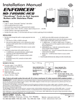
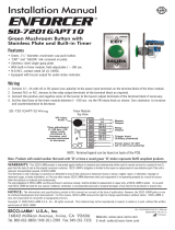
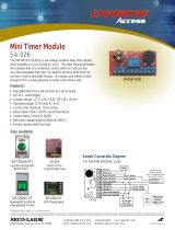
Page is loading ...

SD
-
7217
-
GSBQ
(Single-gang Plate)
SD-7317-GSBQ
(European Plate)
Request-to-Exit Plate with Status LED and
Adjustable Buzzer
Manual
SD
-
7217
-
GSBQ Shown
•
12/24 VDC operation
• Vandal-resistant buzzer with adjustable
sound level for audible status indicator
• Selectable dual-color LED (red/green)
for visual status indicator
•
Buzzer and LED can be configured
separately
• NO/NC contacts rated 10A@125 VAC
• Stainless-steel plate

ENFORCER Request-to-Exit Plate with Status LED and Adjustable Buzzer
2 SECO-LARM U.S.A., Inc.
Overview:
2
3
/
4
"
(70mm)
4
1
/
2
"
(11
5
mm)
EXIT
1
7
/
8
"
(48
mm)
Request to Exit Button
LED Status Indicator
(Off, Red/Green)
Buzzer Indicator
(Volume Adjustable)
Specifications:
Model
SD
-
7217
-
GSBQ
SD
-
7
3
17
-
GSBQ
Plate
Single
-
gang
European
LED
Operating voltage
12VDC or 24
VD
C*
Current draw
15mA@12
VDC
(max.)
Terminals
Red and green wire leads
LED color
Red/Green, selectable
Buzzer
Operating voltage
12VDC or 24
VD
C*
Current draw
27
mA@12
VDC
(max.)
Terminals
Black and gray wire leads
Sound level
85
~
9
8
+/
-
5
dB
@
4" (
1
0c
m
)
(adjustable)
Sound adjustment
Variable resistor (VR)
Pushbutton
Type
NO/NC
Contact Rating
10A@125VAC
Terminals
Screw type
Operating Temperature
-
4°~140° F (
-
20°~60
° C)
Dimensions
4
1
/
2
"
x2
3
/
4
"
x1
7
/
8
"
(11
5
x70x48
mm)
3
3
/
8
"
x3
3
/
8
"
x1
7
/
8
"
(
86
x
86
x
4
8
mm)
Weight
7.6
-
oz (
215
g)
11.3
-
oz (
320
g)
*Using included resistor wired inline on the positive (+) side
Parts List:
1x
RTE plate
2x
Mounting
screws
2x
Resistors
(
1k
Ω, 1/4W)
1x
Manual
Introduction
:
The SD-7217-GSBQ provides great flexibility in a small package by adding both visible and audible
indicators to an RTE plate. The buzzer and LED can be used for a wide variety of installations and may
be configured for separate indications or together depending on the desired application. The buzzer's
volume is adjustable for either noisy or quiet environments. The LED is customizable for either red or
green. Both provide great range of flexibility in application. Some possible uses include providing
indicators for the visually- or hearing-impaired, providing alerts for door open/door unlocked/door
propped open/door forced open detection and many other possibilities.

ENFORCER Request-to-Exit Plate with Status LED and Adjustable Buzzer
SECO-LARM U.S.A., Inc. 3
Installation Instructions:
Before beginning, determine the intended application of both the buzzer and LED as well as whether
they will be used as redundant indicators of one input status or to indicate different input statuses.
Consider also the desired LED color.
1. Run 4~6 wires through the wall to a single-gang back-box as necessary (depending on application):
a. Two wires for the LED light.
b. Two wires for the buzzer.
c. Two wires from the COM terminal and either the N.O. or N.C. terminal of the locking device.
2. Connect the wires from the locking device:
a. For N.C. operation – connect the COM and N.C. wires from the locking device, to the red
colored terminal block of the pushbutton switch (see Fig. 1).
b. For N.O. operation – connect the COM and N.O. wires from the locking device, to the blue
colored terminal block of the pushbutton switch (see Fig. 1).
c. Two wires for the buzzer (see Fig. 2). The polarity must be observed—gray to positive (+) and
black to negative (-).
d. Two wires for the LED (see Fig. 2). Depending on the choice of color for the status LED,
connect the red and green wires according to the LED Color Selection Chart (see Fig. 3).
3. Test and adjust the buzzer volume as desired by turning the volume control knob clockwise to
increase the volume and counterclockwise to decrease the volume (see Fig 2).
4. Screw the plate onto the back-box, taking care not to crimp the wires.
Switch Wiring
Fig. 1
N.O.
N.O.
N.C.
N.C.
Blue
Red
LED Color Selection
Chart
Color Choice Green Wire Red Wire
Green LED
+ -
Red LED
- +
Fig. 3
Green
LED
Resistor
Installation
for 24VDC Applications
Red
LED
Resistor
Resistor
LED Red (-)
LED Green (+)
Buzzer
Gray (+)
Buzzer
Black (
-
)
Resistor
Resistor
LED Red (+)
LED Green (-)
Buzzer Gray (+)
Buzzer Black
(
-
)
Fig. 2
LED Red
LED Green
Buzzer Volume
Control Knob
Switch
Assembly
Buzzer Gray (+)
Buzzer Black (
-
)
Important Note: This device is designed for a 12VDC power supply. When using a 24VDC
power supply, a resistor (included) must be wired in-line with the positive (+) wire of both
the status LED and the buzzer (see below).

ENFORCER Request-to-Exit Plate with Status LED and Adjustable Buzzer
4 SECO-LARM U.S.A., Inc.
Sample Application
s
:
IMPORTANT
:
Users and installers of this product are responsible for ensuring this product complies with all national,
state, and local laws and statutes related to monitoring and recording audio and video signals. SECO-LARM will not be
held responsible for the use of this product in violation of any current laws or statutes.
NOTICE
:
The
SECO
-
LARM policy is one of continual development and improvement.
For
that reason, SECO
-
LARM
reserves the right to change specifications without notice. SECO-LARM is also not responsible for misprints.
Copyright © 2015 SECO-LARM U.S.A., Inc. All rights reserved. This material may not be reproduced or copied, in whole or
in part, without the written permission of SECO-LARM.
WARRANTY:
This
SECO
-
LARM product is warranted against defects in material and workmanship while
used in normal
service for one (1) year from the date of sale to the original customer. SECO-LARM’s obligation is limited to the repair or
replacement of any defective part if the unit is returned, transportation prepaid, to SECO-LARM. This Warranty is void if
damage is caused by or attributed to acts of God, physical or electrical misuse or abuse, neglect, repair or alteration,
improper or abnormal usage, or faulty installation, or if for any other reason SECO-LARM determines that such equipment
is not operating properly as a result of causes other than defects in material and workmanship. The sole obligation of
SECO-LARM and the purchaser’s exclusive remedy, shall be limited to the replacement or repair only, at SECO-LARM’s
option. In no event shall SECO-LARM be liable for any special, collateral, incidental, or consequential personal or property
damage of any kind to the purchaser or anyone else.
N.O.
N.O.
Black (
-
)
Gray (+)
*
Green
*
Red
(+)
(
-
)
N.O.
N.C.
COM
COM
N.C.
N.O.
(+)
(
-
)
Power I/P
Trigger I/P
Relay O/P
Buzzer O/P
12
/24
VDC
Power Supply
–
+
SA-026Q Timer
E-941SA-600
Electromagnetic Lock
+
–
RTE Application #1: Constant On
LED
, Buzzer Sounds When Activated
Green LED shown (For alternate color choice, see pg. 3)
When button is pressed, door is unlocked, LED remains on, and buzzer sounds until door relocks
N.O.
N.O.
Black (
-
)
N.C.
1
COM
1
COM
2
(
–
)
(
+
)
N.C.
2
N.O. 1
N.O. 2
Gray (+)
*
Red
*
Green
12
/24
VDC
Power Supply
–
+
(+)
(
-
)
N.O.
N.C.
COM
COM
N.C.
N.O.
(+)
(
-
)
Power I/P
Trigger I/P
Relay O/P
Buzzer O/P
SR
-
2212
-
C5A
Q
Relay
DPDT
SA-026Q Timer
E-941SA-600
Electromagnetic Lock
+ –
RTE Application #2: Alternating Color LED, Buzzer Sounds When Activated
LED Standby-Red, Unlocked-Green shown (To reverse color choice, see pg. 3)
When button is pressed, door is unlocked, buzzer sounds, and LED changes colors until door relocks
SECO
-
LARM
®
U.S.A., Inc.
16842 Millikan Avenue, Irvine, CA 92606
Website:
www.seco
-
larm.com
Phone: (949) 261
-
2999 | (800) 662
-
0800
Email:
sales@seco
-
larm.com
Note: * indicates resistor locations for 24VDC installations Lock, Timer, and Relay Board not included
®
PITSW1
Order Part#
763
-
183
-
1
%
MI
-
SD7217GSBQ
-
151008.docx
/


