LSI LSIU80ALVD User manual
- Category
- Serial switch boxes
- Type
- User manual
This manual is also suitable for

®
DB15-000320-00
LSIU80ALVD
PCI to Ultra2 SCSI
Host Adapter
USER’S
GUIDE
August 2004
Version 2.0

ii
Electromagnetic Compatibility Notices
This device complies with Part 15 of the FCC Rules. Operation is subject to the following two conditions:
1. This device may not cause harmful interference, and
2. This device must accept any interference received, including interference that may cause undesired operation.
This equipment has been tested and found to comply with the limits for a Class B digital device, pursuant to part
15 of the FCC Rules. These limits are designed to provide reasonable protection against harmful interference in a
residential installation. This equipment generates, uses, and can radiate radio frequency energy and, if not installed
and used in accordance with the instructions, may cause harmful interference to radio communications. However,
there is no guarantee that interference will not occur in a particular installation. If this equipment does cause harmful
interference to radio or television reception, which can be determined by turning the equipment off and on, the user
is encouraged to try to correct the interference by one or more of the following measures:
• Reorient or relocate the receiving antenna.
• Increase the separation between the equipment and the receiver.
• Connect the equipment into an outlet on a circuit different from that to which the receiver is connected.
• Consult the dealer or an experienced radio/TV technician for help.
Shielded cables for SCSI connection external to the cabinet are used in the compliance testing of this Product. LSI
Logic is not responsible for any radio or television interference caused by unauthorized modification of this equipment
or the substitution or attachment of connecting cables and equipment other than those specified by LSI Logic. The
correction of interferences caused by such unauthorized modification, substitution, or attachment will be the
responsibility of the user.
The LSI Logic LSIU80ALVD is tested to comply with FCC standards for home or office use.
This Class B digital apparatus meets all requirements of the Canadian Interference-Causing Equipment Regulations.
Cet appareil numérique de la classe B respecte toutes les exigences du Règlement sur le matériel brouilleur du
Canada.
This is a Class B product based on the standard of the Voluntary Control Council for Interference from Information
Technology Equipment (VCCI). If this is used near a radio or television receiver in a domestic environment, it may
cause radio interference. Install and use the equipment according to the instruction manual.
LSI Logic Corporation
North American Headquarters
Milpitas, CA
408.433.8000

iii
This document contains proprietary information of LSI Logic Corporation. The
information contained herein is not to be used by or disclosed to third parties
without the express written permission of an officer of LSI Logic Corporation.
LSI Logic products are not intended for use in life-support appliances, devices,
or systems. Use of any LSI Logic product in such applications without written
consent of the appropriate LSI Logic officer is prohibited.
Document DB15-000320-00, August 2004
This document describes the LSI Logic LSIU80ALVD PCI to Ultra2 SCSI Host
Adapter and will remain the official reference source for all revisions/releases of
this product until rescinded by an update.
LSI Logic Corporation reserves the right to make changes to any products herein
at any time without notice. LSI Logic does not assume any responsibility or
liability arising out of the application or use of any product described herein,
except as expressly agreed to in writing by LSI Logic; nor does the purchase or
use of a product from LSI Logic convey a license under any patent rights,
copyrights, trademark rights, or any other of the intellectual property rights of LSI
Logic or third parties.
Copyright © 2004 by LSI Logic Corporation. All rights reserved.
TRADEMARK ACKNOWLEDGMENT
LSI Logic, the LSI Logic logo design, TolerANT, SDMS, and LVDlink are
trademarks or registered trademarks of LSI Logic Corporation. All other brand
and product names may be trademarks of their respective companies.
DB
To receive product literature, visit us at http://www.lsilogic.com.
For a current list of our distributors, sales offices, and design resource
centers, view our web page located at
http://www.lsilogic.com/contacts/index.html

iv

Preface v
Preface
This book is the primary reference and user’s guide for the LSIU80ALVD
PCI to Ultra2 SCSI Host Adapter. It contains a complete functional
description for the LSIU80ALVD and includes complete physical and
electrical specifications for the LSIU80ALVD.
Audience
This document assumes that you have some familiarity with
microprocessors and related support devices. The people who benefit
from this book are:
• Engineers and managers who are evaluating the processor for
possible use in a system
• Engineers who are designing the processor into a system
Organization
This document has the following chapters and appendixes:
• Chapter 1, Using the LSIU80ALVD, defines the interfaces and
characteristics of the LSIU80ALVD.
• Chapter 2, Installing the LSIU80ALVD, provides both quick and
detailed installation instructions.
• Chapter 3, Configuring the LSIU80ALVD, describes the SCSI BIOS
Configuration Utility to configure adapter and device settings.
• Appendix A, Technical Specifications, describes the physical and
operational environments of the LSIU80ALVD.
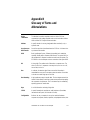
• Appendix B, Glossary of Terms and Abbreviations, provides
definitions of various terminology that is referenced throughout this
user’s guide.

vi Preface
Related Publications
PCI Storage Device Management System SDMS™ 4.0 User’s Guide,
Document DB15-000099-01
Revision Record
Revision Date Remarks
2.0 8/04 Final version. First printing.

Contents vii
Contents
Chapter 1
Using the LSIU80ALVD
1.1 General Description 1-1
1.2 Features 1-2
1.2.1 PCI Interface 1-2
1.2.2 SCSI Interface 1-2
1.2.3 Board Characteristics 1-3
1.3 Interface Descriptions 1-3
1.3.1 The PCI Interface 1-3
1.3.2 The SCSI Interface 1-4
1.3.3 Ultra2 SCSI Technology 1-5
1.3.4 LVDlink Technology 1-5
1.3.5 On-Board LED 1-6
Chapter 2
Installing the LSIU80ALVD
2.1 Quick Installation Procedure 2-1
2.2 Detailed Installation Procedure 2-3
2.2.1 Before You Start 2-3
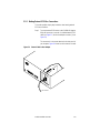
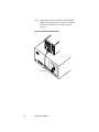
2.2.2 Inserting the Host Adapter 2-4
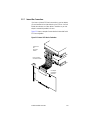
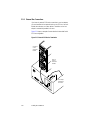
2.2.3 Connecting the SCSI Peripherals 2-7
2.2.4 Making Internal SCSI Bus Connections 2-10
2.2.5 Making External SCSI Bus Connections 2-15
2.2.6 SCSI Bus Termination 2-18
2.2.7 Internal Bus Connections 2-19
2.2.8 External Bus Connections 2-20
2.2.9 Internal and External Bus Connections 2-21
2.2.10 Setting SCSI IDs 2-22
2.3 Completing the Installation 2-24

viii Contents
Chapter 3
Configuring the LSIU80ALVD
3.1 When to Configure the LSIU80ALVD 3-1
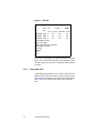
3.2 Starting the SCSI BIOS Configuration Utility 3-2
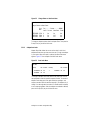
3.2.1 Configuration Utility Main Menu 3-3
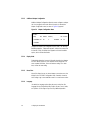
3.2.2 Utilities Menu 3-7
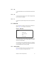
3.2.3 Device Selections Menu 3-11
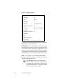
3.3 Exiting the SCSI BIOS Configuration Utility 3-14
Appendix A
Technical Specifications
A.1 Physical Environment A-1
A.1.1 Physical Characteristics A-1
A.1.2 Electrical Characteristics A-2
A.1.3 Thermal, Atmospheric Characteristics A-3
A.1.4 Electromagnetic Compliance A-3
A.1.5 Safety Characteristics A-3
A.2 Operational Environment A-4
A.2.1 The PCI Interface A-4
A.2.2 The SCSI Interface A-7
A.2.3 On-Board LED A-10
A.2.4 The SCSI Busy LED A-10
Appendix B
Glossary of Terms and Abbreviations
Index
Customer Feedback

Contents ix
Figures
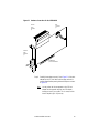
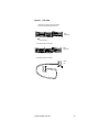
2.1 Hardware Connections for the LSIU80ALVD 2-5
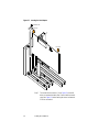
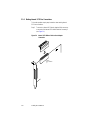
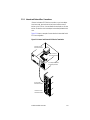
2.2 Inserting the Host Adapter 2-6
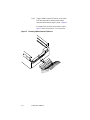
2.3 SCSI Cables 2-9
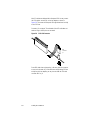
2.4 Internal SCSI Ribbon Cable to Host Adapter Connection 2-10
2.5 Internal SCSI Ribbon Cable to Internal SCSI Device
Connection 2-11
2.6 Connecting Additional Internal SCSI Devices 2-12
2.7 Multiple Internal SCSI Devices Chained Together 2-13
2.8 SCSI LED Connector 2-14
2.9 External Cable to Host Adapter 2-15
2.10 External SCSI Device Cable 2-16
2.11 Multiple External SCSI Devices Chained Together 2-17
2.12 Internal SCSI Device Termination 2-19
2.13 External SCSI Device Termination 2-20
2.14 Internal and External SCSI Device Termination 2-21
3.1 Main Menu 3-4
3.2 Change Status on Next Boot Menu 3-5
3.3 Boot Order Menu 3-5
3.4 Adapter Configuration Menu 3-6
3.5 Utilities Menu 3-7
3.6 Adapter Setup Menu 3-8
3.7 Device Selections Menu 3-11
A.1 LSIU80ALVD Mechanical Drawing A-2

x Contents

Contents xi
Tables
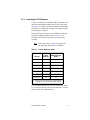
2.1 SCSI Bus Widths and Speeds 2-7
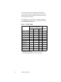
2.2 SCSI Bus Lengths 2-8
2.3 SCSI ID Record 2-23
3.1 Global Default Settings 3-1
3.2 Device Default Settings 3-2
A.1 Maximum Power Requirements A-2
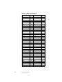
A.2 PCI Connector J1 (Front) A-5
A.3 PCI Connector J1 (Back) A-6
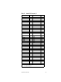
A.4 Internal SCSI Connector J2 A-8
A.5 External SCSI Connector J3 A-9
A.6 LED Connector J4 A-10

xii Contents

LSIU80ALVD PCI to Ultra2 SCSI Host Adapter 1-1
Chapter 1
Using the LSIU80ALVD
This chapter describes the LSIU80ALVD PCI to Ultra2 SCSI Host
Adapter board interface to PCI computer systems and includes these
topics:
• Section 1.1, “General Description,” page 1-1
• Section 1.2, “Features,” page 1-2
• Section 1.3, “Interface Descriptions,” page 1-3
1.1 General Description
The LSIU80ALVD provides an Ultra2 SCSI interface to PCI computer
systems. It will be referred to as the LSIU80ALVD throughout this
manual. Installing this adapter in your PCI system allows connection of
up to 15 SCSI devices.
The LSIU80ALVD is a 16-bit, Low Voltage Differential (LVD)/Single-
Ended (SE) SCSI solution for your computer. This board can support
legacy Fast SCSI and Ultra SCSI devices, and the newest LVD Ultra2
SCSI devices. It is also backwards compatible with existing wide SCSI
applications for the LSI8251S and LSI8751SP/E host adapters.
The Storage Device Management System (SDMS™) software operates
the board. Other SCSI software that works with the LSI53C895A PCI to
Ultra2 Controller with LVDlink™ Universal Transceivers chip could also
be used. BIOS support for this adapter is incorporated on the board in a
Flash memory device. The LSIU80ALVD has a serial EEPROM device
for storing the user’s SCSI bus configuration.
This guide, along with the PCI Storage Device Management System
SDMS 4.0 User’s Guide, contains product information and installation
instructions to help you gain the full benefits of the LSIU80ALVD.

1-2 Using the LSIU80ALVD
1.2 Features
This section provides a high level overview of the PCI Interface, the SCSI
Interface, and Board Characteristics for the LSIU80ALVD.
1.2.1 PCI Interface
• Full 32-bit DMA bus master
• Zero wait-state bus master data bursts up to 133 Mbytes/s
(@ 33 MHz)
• Universal 3.3 V and 5 V PCI bus voltage support
• Supports 32-bit 33 MHz data bursts with variable burst lengths
• Bursts 2 to 128 dwords across the PCI bus
• Prefetches up to 8 Dwords of SCRIPTs instructions
• Supports PCI Write and Invalidate, Read Line, and Read Multiple
commands
1.2.2 SCSI Interface
• Supports 16-bit LVD and SE signaling
• Includes 4 Kbytes RAM for SCRIPTs instruction storage
• Automatically enables LVD or SE termination
• Contains external 68-pin high density (HD) and internal 68-pin HD
latching connectors
• Performs wide Ultra2 SCSI LVD synchronous transfers up to
80 Mbytes/s
• SCSI synchronous offset up to 31
• Provides SCSI termination power (TERMPWR) source with
autoresetting circuit protection device
• SCSI Configured AutoMatically (SCAM) Level 1 Capability
(Set “OFF” by default)
• Flash ROM for BIOS storage for up to 256 Kbytes
• Supports variable block size and scatter/gather data transfers

Interface Descriptions 1-3
• Performs complex SCSI bus sequences without interrupts, including
restore data pointers
• Serial EEPROM for user configuration utility
• SCSI bus activity LED connector and on-board LED
1.2.3 Board Characteristics
• PCI board dimensions,
152.4 x 88.90 mm (6.00 x 3.5 inches)
• PCI Universal 32-bit card edge connector
• HD 68-pin external connector
• HD 68-pin internal connector
A mechanical drawing showing board dimensions and component layout
is located in Appendix A, “Technical Specifications.”
1.3 Interface Descriptions
This section provides a more detailed explanation about the PCI
Interface, the SCSI Interface, Ultra2 SCSI Technology, and LVDlink
Technology.
1.3.1 The PCI Interface
PCI is a high-speed standard local bus for interfacing a number of I/O
components to the processor and memory subsystems in equipment
ranging from PCs to servers. The PCI functionality for the LSIU80ALVD
is contained within the LSI53C895A. The LSI53C895A connects directly
to the PCI bus and generates signal timing and bus protocol in
compliance with the PCI Specification Revision 2.1.
The PCI interface operates as a 32-bit DMA bus master. The connection
is made through edge connector J1 (see Figure 2.1). The signal
definitions and pin numbers conform to the PCI Local Bus Specification
Revision 2.1 standard. The LSIU80ALVD conforms to the PCI universal
signaling environment for a 5 V or 3.3 V PCI bus.

1-4 Using the LSIU80ALVD
1.3.2 The SCSI Interface
The SCSI functionality for the LSIU80ALVD is contained within the
LSI53C895A. The LSI53C895A connects directly to the SCSI bus and
generates signal timing and bus protocol in compliance with the SCSI
standard.
The SCSI interface on the LSIU80ALVD operates as an 8-bit or 16-bit
interface. It supports 8-bit or 16-bit, synchronous and asynchronous, LVD
or SE, Fast, Ultra and Ultra2 SCSI protocols in various combinations.
The interface is made through connectors J2 and J3 (see Figure 2.1).
Internal connector J2 is a 68-pin HD right angle latching connector.
External connector J3 is a shielded 68-pin HD right angle connector that
protrudes through the back panel bracket.
An on-board LED (labeled Activity) indicates SCSI bus activity.
LVD/SE dual mode, active termination is provided on the LSIU80ALVD.
Termination is automatically disabled when both SCSI connectors are
used.
The LSIU80ALVD supplies SCSI bus TERMPWR through a blocking
diode and a self-resetting 1.5 A short circuit protection device.
A 40 MHz oscillator is installed on the LSIU80ALVD to provide the clock
frequency to the LSI53C895A that is necessary to support Ultra2 SCSI
transfers of up to 80 Mbytes/s.

Interface Descriptions 1-5
1.3.3 Ultra2 SCSI Technology
The LSIU80ALVD fully supports Ultra2 SCSI. Ultra2 SCSI is an extension
of the SCSI Parallel Interface 2 and 3 (SPI-2 and SPI-3) family of
standards that expands the bandwidth of the SCSI bus, allowing faster
synchronous data transfers.
For the internal bus, special impedance SCSI ribbon cables are specified
for operation with Ultra and Ultra2 SCSI devices. You must consider the
total length of the bus cables and the number of devices on the SCSI
bus when setting up your system.
Use SCSI cables that have been rated for standard SCSI (Fast, Ultra,
and Ultra2) environments.
See Chapter 2, “Installing the LSIU80ALVD,” for a detailed explanation of
SCSI bus connections.
1.3.4 LVDlink Technology
To support greater device connectivity and a longer SCSI cable, the
LSIU80ALVD features LVDlink technology, the LSI Logic implementation
of Universal LVD SCSI. LVDlink transceivers provide the inherent
reliability of differential SCSI, and a long-term migration path to faster
SCSI transfer rates.
The LVDlink transceivers reduce the power needed to drive the SCSI
bus, so that the I/O drivers can be integrated directly into the chip.
LVDlink technology lowers the amplitude of noise reflections and allows
higher transmission frequencies.
The LVDlink transceivers operate in LVD and SE modes. They also allow
the chip to detect a High Voltage Differential (HVD) signal when the chip
is mistakenly connected to external HVD transceivers. The LSI53C895A
automatically detects which type of signal is connected, based on the
voltage detected, and automatically switches as needed to the SE or LVD
mode. All bus devices must be LVD or SE. If a HVD device is detected,
the board puts the SCSI bus in the high impedance state and shuts
down.

1-6 Using the LSIU80ALVD
1.3.4.1 Benefits of LVDlink
The LSI53C895A supports LVD for SCSI, which is a signaling technology
that increases the reliability of SCSI data transfers over longer distances
than supported by SE SCSI. The low current output of LVD allows the
I/O transceivers to be integrated directly into the chip. LVD provides the
reliability of HVD SCSI without the added cost of external differential
transceivers. Ultra2 SCSI with LVD allows a longer SCSI cable and more
devices on the bus, using the same cables defined in the SCSI-3 parallel
Interface (SPI-2) standard for Ultra SCSI.
Important: To utilize Ultra2 SCSI performance, the user must only
have LVD devices on the bus. Do not mix any SE devices
with LVD devices as the entire bus will drop to SE with
maximum Ultra SCSI performance.
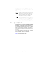
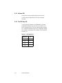
1.3.5 On-Board LED
On-board LEDs are used to indicate the status of the SCSI bus.
The SCSI Activity LED lights when the SCSI bus is transferring
information.

LSIU80ALVD PCI to Ultra2 SCSI Host Adapter 2-1
Chapter 2
Installing the
LSIU80ALVD
This chapter provides instructions on how to install the LSIU80ALVD and
includes these topics:
• Section 2.1, “Quick Installation Procedure,” page 2-1
• Section 2.2, “Detailed Installation Procedure,” page 2-3
• Section 2.3, “Completing the Installation,” page 2-24
2.1 Quick Installation Procedure
This section is provided for the experienced computer user with prior host
adapter installation and SCSI bus setup experience. If you prefer a more
detailed guidance for installing the LSIU80ALVD, follow the instructions
in the Section 2.2, “Detailed Installation Procedure.”
For safe and proper installation, check the user’s manual supplied with
your computer and perform the following steps.
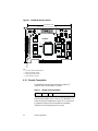
Step 1. Ground yourself before removing this host adapter board.
Remove the LSIU80ALVD from the packing and check that it is
not damaged. An example of this host adapter board is shown
in Figure 2.1.
Step 2. Switch off and unplug the system.
Step 3. Remove the cabinet cover on your computer to access the PCI
slots.
Caution: Ground yourself by touching a metal surface before
handling boards. Static charges on your body can damage
electronic components. Handle plug-in boards by the edge;
do not touch board components or gold connector contacts.
The use of a static ground strap is recommended.

2-2 Installing the LSIU80ALVD
Step 4. Locate the slots for installing a PCI plug-in board. The
LSIU80ALVD requires a PCI slot that allows bus master
operation. See Table 2.2.
Step 5. Remove the blank bracket panel on the back of the computer
aligned with the PCI slot you intend to use. Save the bracket
screw.
Step 6. Carefully insert the edge connector J1 of the host adapter into
the PCI slot. Make sure the edge connector is properly aligned
before pressing the board into place. See Figure 2.2.
Note: You may notice that the components on a PCI host adapter
face the opposite way from non-PCI adapter boards you
have in your system. This is correct, and the board is keyed
to go in only one way.
Step 7. The bracket around connector J3 (see Figure 2.1) should fit
where the blank bracket panel was removed. Secure the
bracket with the bracket screw before making the internal and
external SCSI bus connections.
Step 8. If you are connecting any internal SCSI devices, plug a 68-pin
connector on the end of the internal SCSI ribbon cable into
connector J2 (see Figure 2.1). Make certain to match pin 1 on
both connectors.
Step 9. Connect the LED cable if desired. This is designed to drive an
off-board system LED and indicates activity on the SCSI bus.
The off-board LED will operate at the same time as the
on-board SCSI Activity LED.
Step 10. Replace the cabinet cover as described in the user’s manual for
your computer.
Step 11. Make all external SCSI bus connections. Finally, refer to the
PCI Storage Device Management System SDMS 4.0 User’s
Guide (or the guide for the software you will use) to load the
driver software for your particular operating system.
Remember: The SCSI bus requires proper termination, and no duplicate
SCSI IDs.
Page is loading ...
Page is loading ...
Page is loading ...
Page is loading ...
Page is loading ...
Page is loading ...
Page is loading ...
Page is loading ...
Page is loading ...
Page is loading ...
Page is loading ...
Page is loading ...
Page is loading ...
Page is loading ...
Page is loading ...
Page is loading ...
Page is loading ...
Page is loading ...
Page is loading ...
Page is loading ...
Page is loading ...
Page is loading ...
Page is loading ...
Page is loading ...
Page is loading ...
Page is loading ...
Page is loading ...
Page is loading ...
Page is loading ...
Page is loading ...
Page is loading ...
Page is loading ...
Page is loading ...
Page is loading ...
Page is loading ...
Page is loading ...
Page is loading ...
Page is loading ...
Page is loading ...
Page is loading ...
Page is loading ...
Page is loading ...
Page is loading ...
Page is loading ...
Page is loading ...
Page is loading ...
Page is loading ...
Page is loading ...
Page is loading ...
Page is loading ...
Page is loading ...
Page is loading ...
Page is loading ...
Page is loading ...
Page is loading ...
Page is loading ...
Page is loading ...
Page is loading ...
-
 1
1
-
 2
2
-
 3
3
-
 4
4
-
 5
5
-
 6
6
-
 7
7
-
 8
8
-
 9
9
-
 10
10
-
 11
11
-
 12
12
-
 13
13
-
 14
14
-
 15
15
-
 16
16
-
 17
17
-
 18
18
-
 19
19
-
 20
20
-
 21
21
-
 22
22
-
 23
23
-
 24
24
-
 25
25
-
 26
26
-
 27
27
-
 28
28
-
 29
29
-
 30
30
-
 31
31
-
 32
32
-
 33
33
-
 34
34
-
 35
35
-
 36
36
-
 37
37
-
 38
38
-
 39
39
-
 40
40
-
 41
41
-
 42
42
-
 43
43
-
 44
44
-
 45
45
-
 46
46
-
 47
47
-
 48
48
-
 49
49
-
 50
50
-
 51
51
-
 52
52
-
 53
53
-
 54
54
-
 55
55
-
 56
56
-
 57
57
-
 58
58
-
 59
59
-
 60
60
-
 61
61
-
 62
62
-
 63
63
-
 64
64
-
 65
65
-
 66
66
-
 67
67
-
 68
68
-
 69
69
-
 70
70
-
 71
71
-
 72
72
-
 73
73
-
 74
74
-
 75
75
-
 76
76
-
 77
77
-
 78
78


LSI LSIU80ALVD User manual
- Category
- Serial switch boxes
- Type
- User manual
- This manual is also suitable for
Ask a question and I''ll find the answer in the document
Finding information in a document is now easier with AI
Related papers
-
LSI LSI8750SP PCI to Ultra SCSI Host Adapter User guide
-
-
-
-
-
-
-
-
-
Other documents
-
Broadcom LSI53C1020 Ultra320 SCSI User guide
-
-
-
Adaptec AHA-3950U2 User guide
-
-
Black Box SC120A-R2 User manual
-
-
HP A6829A User manual
-
-
Tyan S2257 THUNDER 2400 User manual